Table of Contents
Advertisement
Quick Links
Advertisement
Table of Contents

Subscribe to Our Youtube Channel
Related Manuals for Silca Matrix One


Summary of Contents for Silca Matrix One
- Page 1 Operating Manual Original Instructions D443308XA vers. 1.0...
- Page 2 (c) 2014 SILCA S.p.a. - Vittorio Veneto This manual has been drawn up by SILCA S.p.a. All rights reserved. No part of this publication can be reproduced or circulated by any means whatsoever (photocopies, microfi lm or other) without the consent of SILCA S.p.A.
-
Page 3: Table Of Contents
INDEX USE OF THE MANUAL ........................1 TERMINOLOGY ..........................2 1 MACHINE DESCRIPTION ........................5 1.1 WORKING PARTS ........................6 1.2 ACCESSORIES PROVIDED .....................7 1.3 TECHNICAL DATA ........................7 ELECTRIC DIAGRAM ......................8 2 HANDLING ............................9 2.1 PACKING ............................9 2.2 TRANSPORT ..........................9 2.3 UNPACKING ..........................9 2.4 HANDLING THE MACHINE ......................9 3 MACHINE INSTALLATION AND PREPARATION ................10 3.1 CHECKING FOR DAMAGE ......................10... - Page 4 6.5 REPLACING THE LAMP ......................24 6.6 ADJUSTING/REPLACING THE VERTICAL CARRIAGE SPRING ...........25 6.7 CHECKING AND REPLACING FUSES ..................26 6.8 REPLACING THE CALIBRATION KEY PAD ELECTRONIC CIRCUIT BOARD.......27 6.9 REPLACING THE CONDENSER .....................27 6.10 REPLACING THE MOTOR .......................28 6.11 REPLACING THE TRANSFORMER ..................28 6.12 REPLACING SWITCHES: MASTER AND MOTOR ON ............29 6.13 ALIGNING/CALIBRATING THE CLAMP ...................30 6.13.1 CONTROL ALIGNMENT LEFT-HAND STATIONARY JAWS ..........30...
-
Page 5: Use Of The Manual
This manual must be read and its contents acquired by those who will use it . The MATRIX ONE key-cutting machine is designed for professional use by adults of either gender in full possession of their physical, sensorial or mental capacities. -
Page 6: Terminology
Matrix ONE Operating manual TERMINOLOGY For those inexperienced in the subject of keys and key cutting, below is an illustration of the most frequently used terms: Fig. 2 1) Head 3) Stop 5) Tip 7) Cuts 2) Neck 4) Stem... - Page 7 Matrix ONE Operating manual GRAPHICS IN THE USER’S MANUAL Obligation to read Activation of Deactivation of Pay attention the manual tracer point spring tracer point spring GRAPHICS ON THE MATRIX-ONE KEY-CUTTING MACHINE Obligatory use of Tracer point spring Tracer point spring safety goggles (chap.
- Page 8 Any other use different from that indicated in this manual will cause the forfeiture of all customers’ rights to make claims on Silca S.p.A. and may be an unknown source of hazard for the operator or third parties. ATTENTION: negligent use or failure by the operator to observe the instructions in this manual are not covered by the warranty and the manufacturer declines any responsibility in such cases.
-
Page 9: Machine Description
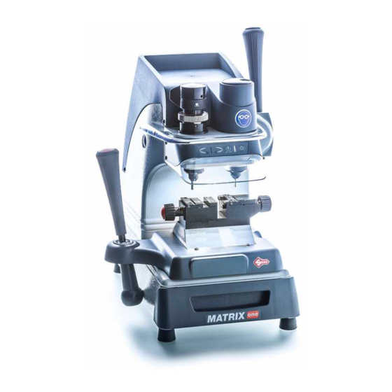
Matrix ONE Operating manual 1 MACHINE DESCRIPTION The MATRIX-ONE key-cutting machine gives excellent technical performance of great precision. The standard clamp on MATRIX-ONE is used to cut some of the following types of keys: • keys with fl at dimple cuts •... -
Page 10: Working Parts
Matrix ONE Operating manual 1.1 WORKING PARTS Fig. 5 A - clamp carriage (X-Y axes) K - calibration unit key pad B - clamp N - tracer point spring cam C - clamp carriage lever (X-Y axes) P - ON/OFF switch... -
Page 11: Accessories Provided
Matrix ONE Operating manual 1.2 ACCESSORIES PROVIDED MATRIX ONE comes with a series of accessories for use and maintenance (tools, hex wrenches, fuses, etc.) provided in a special holder: fuse 2 pcs F1 cutter 2,5 Amp rapid (230V) T1 tracer point 2.5 mm hex wrench mm... -
Page 12: Electric Diagram
Matrix ONE Operating manual ELECTRIC DIAGRAM Fig. 6 1) Fuses: 2,5 Amp (230V) 8) Transformer 2) Safety switch 9) LED circuit 3) Terminal board 10) LED lamp 4) Motor ON/OFF switch 11) Tracer point contact 5) Motor 6,3 mF (230V) -
Page 13: Handling
Matrix ONE Operating manual 2 HANDLING The MATRIX ONE key-cutting machine is easy to handle and there are no special hazards involved in moving it. The packed machine can by carried manually by one person. 2.1 PACKING The packing for the MATRIX-ONE key-cutting machine ensures safe handling of the machine and all its components. -
Page 14: Machine Installation And Preparation
3.1 CHECKING FOR DAMAGE MATRIX ONE is a solid compact machine and will not break if handling, unpacking and installation are carried out to the instructions in this manual. However, it is good practice to check that the machine has not been damaged. -
Page 15: Work Station Description
Matrix ONE Operating manual 3.5 WORK STATION DESCRIPTION The machine is operated by a single person using the following controls: • ON/OFF master switch (P) located on the right- hand side of the machine. • Motor ON/OFF switch (Q). •... -
Page 16: Starting The Key-Cutting Machine
Matrix ONE Operating manual 3.6 STARTING THE KEY-CUTTING MACHINE 1) Connect the power lead. 2) Turn on the key-cutting machine with the master switch (P). A beep sounds and for a second all the warning lights (leds) on the key pad/control board (K) light up simultaneously on the machine front (blue vertical bar –... -
Page 17: Machine Calibration And Regulation
Matrix ONE Operating manual 4 MACHINE CALIBRATION AND REGULATION Before carrying out cutting operations the clamps and tools must be regulated. According to the type of key to be cut, activate or deactivate the spring device provided with the machine to facilitate cutting operations: •... -
Page 18: Micrometer Gauge
Matrix ONE Operating manual 4.2 MICROMETER GAUGE The micrometer gauge is used for tool alignment and also for adjusting small variations in depths often necessary on worn keys. After tool alignment (green bar) the depth of cuts can be reduced or increased by turning the micrometer gauge (V) to the left or right. -
Page 19: Calibration / Tool Alignment
Matrix ONE Operating manual 4.3 CALIBRATION / TOOL ALIGNMENT Carry out this operation with the key-cutting machine on. ATTENTION: check that the motor start switch (Q) is off. 1) Turn the cam (N) clockwise all the way to disable the tracer point spring (chap.4.4). -
Page 20: Tracer Point Spring
Matrix ONE Operating manual Fig. 19 4.4 TRACER POINT SPRING The machine comes with a rapid system for enabling or disabling the tracer point spring. • To enable the tracer point spring function Turn/push the cam (N) all the way anti-clockwise . -
Page 21: Clamps
Matrix ONE Operating manual 4.5 CLAMPS Clamps come with easily replaced special key-locking jaws (B1) (B2) and (B3). Fig. 21 KEYS WITH DIMPLE CUTS AND LASER KEYS Fig. 22 Copyright Silca 2014... -
Page 22: Cutting
Matrix ONE Operating manual 5 CUTTING ATTENTION: Please see the following warnings to ensure completely safe cutting operations: • Always work with dry hands. • Check that the machine is earthed. • Wear the safety goggles even when the machine has a safety shield. -
Page 23: Cutting Dimple Keys
Matrix ONE Operating manual 5.3 CUTTING DIMPLE KEYS 1) Enable the tracer point spring (chap. 4.4). 2) Press the motor on switch (Q). 3) Insert the two keys into their clamps. 4) Take care when positioning the keys: Stop 0 for keys with stops. -
Page 24: Cutting Laser Type Keys
Matrix ONE Operating manual 5.4 CUTTING LASER TYPE KEYS 1) Disable the tracer point spring (chap. 4.4). 2) Turn on the motor with the switch (Q). 3) Insert the two keys into their clamps. 4) Take care when positioning the keys: Stop 0 for keys with stops (chap. -
Page 25: Cutting Laser Keys With Narrow Stems (Mercedes)
Matrix ONE Operating manual 5.5 CUTTING LASER KEYS WITH NARROW STEMS (MERCEDES) WITH OPTIONAL ADAPTER “M” code D910533ZR Fig. 29 HU41P - HU64P - HU64T - HU81T HU55P Fig. 30 5.6 CUTTING FICHET TYPE KEYS (H PROFILE) WITH OPTIONAL ADAPTER “F”... -
Page 26: Maintenance
ATTENTION: when repairing or replacing parts the “CE” label is guaranteed only if original spare parts provided by the manufacturer are used. The MATRIX ONE key-cutting machine does not need special maintenance, but it is good practice to check and if necessary replace parts subject to wear: belts, lamp and vertical carriage spring. -
Page 27: Removing The Upper Front Unit
Matrix ONE Operating manual Tightening: Increase belt tension by pushing the motor towards the back of the machine . Replacing: 1) Loosen the belt by pushing the motor gently towards the tracer point and cutter. 2) Remove the belt and replace. -
Page 28: Replacing The Transparent Safety Shield
Matrix ONE Operating manual 6.4 REPLACING THE TRANSPARENT SAFETY SHIELD 1) Remove the upper front unit (chap6.2). 2) Use a screwdriver to detach the shield from the upper front unit. 3) Attach the new shield to the upper front unit. -
Page 29: Adjusting/Replacing The Vertical Carriage Spring
Matrix ONE Operating manual 6.6 ADJUSTING/REPLACING THE VERTICAL CARRIAGE SPRING If the vertical carriage (Z axis) seems loose it is advisable to adjust the spring and replace if necessary. Proceed as follows: 1) Switch off the machine and disconnect the power lead. -
Page 30: Checking And Replacing Fuses
Fuses should be checked with an instrument for measuring continuity (tester, ohmeter, multimeter, etc.) as they may appear normal to the eye even when electrically damaged. Each fuse must be replaced with one of the same value (Amperes) and type (rapid or delayed), as shown in the manual. The MATRIX ONE key-cutting machine has:... -
Page 31: Replacing The Calibration Key Pad Electronic Circuit Board
Matrix ONE Operating manual 6.8 REPLACING THE CALIBRATION KEY PAD ELECTRONIC CIRCUIT BOARD If the key pad (K) is not working properly replace the electronic circuit board inside it as described below: 1) Remove the upper front unit (chap6.2). 2) Detach the connectors (J4 and (R4) (Fig. 47). -
Page 32: Replacing The Motor
Matrix ONE Operating manual 6.10 REPLACING THE MOTOR 1) Disconnect the key-cutting machine from the mains. 2) Loosen the 6 screws (Y1) and remove the top cover (Fig. 33). 3) Loosen the 2 screws (W1) fi xing the motor wires to the terminal board and the screw on the earth wire (W2). -
Page 33: Replacing Switches: Master And Motor On
Matrix ONE Operating manual Fig. 52 Fig. 53 6.12 REPLACING SWITCHES: MASTER AND MOTOR ON 1) Disconnect the power lead from the machine . 2) Turn the key-cutting machine onto its back and loosen the 4 screws (P4) to remove the bottom safety guard (Fig. -
Page 34: Aligning/Calibrating The Clamp
Matrix ONE Operating manual 6.13 ALIGNING/CALIBRATING THE CLAMP The key-cutting machine comes from Silca with the clamp perfectly aligned. Alignment is necessary only if a jaw has to be replaced. 1) Make sure the motor ON switch is OFF. 2) Fit and secure the 2 calibrating pins (provided) to the 2 spindles as if they were tools. N.B.: the fl at part (with greater diameter) must be visible (towards the clamp). -
Page 35: Replacing The Jaws
Matrix ONE Operating manual Fig. 59 6.14 REPLACING THE JAWS Make sure the motor ON switch is OFF . 6.14.1 REPLACING THE FIXED JAWS 1) Loosen the 2 screws (B6) or (B7) and remove the jaw . 2) Fit the new jaw up against the left-hand side and align also from the front (Fig. 61). -
Page 36: Replacing Mobile Jaw On Left-Hand Clamp
Matrix ONE Operating manual 6.14.2 REPLACING MOBILE JAW ON LEFT-HAND CLAMP 1) Fully unscrew the knob (E). 2) Loosen the 2 screws (H3) and remove the plate (H4) (Fig. 62) . 3) Remove the mobile jaw and clean the clamp (Fig. 63). -
Page 37: Disposal
Matrix ONE Operating manual 7 DISPOSAL For correct disposal please refer to current standards. INFORMATION FOR USERS OF PROFESSIONAL EQUIPMENT From “Actuation of Directive 2012/19/EU regarding Waste Electrical and Electronic Equipment (WEEE)” The symbol of a crossed waste bin found on equipment or its packing indicates that at the end of the product’s useful life it must be collected separately from other waste so that it can be properly treated and recycled. -
Page 38: After-Sales Service
8 AFTER-SALES SERVICE Silca provides full service to purchasers of the MATRIX ONE machine. To ensure total safety for the operator and the machine, any operations not specifi ed in this manual shall be carried out by the manufacturer or in the special Service Centres recommended by Silca. - Page 39 | 14 | European Union DIRECTIVE 2006/95/CE (Low Voltage) and with the EN 60950-1 ; EN 62233 Standards Claudio Tomasella of the Silca S.p.A. Research & Development Division is authorized to create a Technical File. General Manager Basic Production Center...
- Page 40 Hong Kong plc@plc.com.hk 23 Man Lock Street +36-1-3290692 Hungary Kaba Elzett Megyeri út 51 Budapest 1044 +36-1-3501011 info@elzett.hu Minda Silca Engineering +91-987-397630 +91-120-2351301 India Plot No. 37, Toy City Greater Noida 201308 Ltd. +91-987-397631 info@mindasilca.in No.73 Stakhr. St - Emam...
- Page 41 +381-11-3290017 Serbia Silkon D.O.O. 29, Novembra 70 Belgrade 11000 +381-11-2080200 silkon@ptt.yu 21 Toh Guan Rd. East +65-6316-4470 Singapore Silca Soxxi Pte. Ltd. Singapore 608609 +65-6316-8100 #01-12 Toh Guan Centre info@silca.sg +421-2-6252-0032 +421-2-6252-0034 Slovakia H&B Slovakia s.r.o. Ovsistske Nam. 1 Bratislava...
- Page 42 SILCA S.p.A. Via Podgora, 20 (Z.I.) 31029 VITTORIO VENETO (TV) Tel. 0438 9136 Fax 0438 913800 E-mail: silca@silca.it www.silca.biz Members of the Kaba Group...
Need help?
Do you have a question about the Matrix One and is the answer not in the manual?
Questions and answers