Table of Contents
Advertisement
Quick Links
Advertisement
Table of Contents

Subscribe to Our Youtube Channel
Related Manuals for Silca D429724XA


Summary of Contents for Silca D429724XA
- Page 1 Technica Technica Operating manual D429724XA vers. ®...
- Page 2 This manual has been drawn up by SILCA S.p.A. All rights reserved. No part of this publication may be reproduced or used in any form or by any means (photocopying, microfilm or other) without the written permission of SILCA S.p.A. Edition: september 2005 Printed in Vittorio Veneto by SILCA S.p.A.
-
Page 3: Table Of Contents
INDEX GUIDE TO THE MANUAL ......................1 GENERAL ..........................2 MACHINE DESCRIPTION ..................4 Main Characteristics ...................4 Working parts .....................5 Technical Data ....................6 Accessories provided ..................6 Safety .........................7 Electric circuit .....................7 TRANSPORT ......................8 Packing .......................8 Unpacking ......................8 Machine handling ....................8 MACHINE INSTALLATION AND PREPARATION ............9 Checking for damage ..................9 Positioning ......................9 Description of work station .................9... -
Page 5: Guide To The Manual
Common technical terms are used in this manual. To assist those with little experience of keys and key-cutting, below is an illustration of the terms most frequently used. Fig. 1 1) Head 2) Rim 3) Tip 4) Bit 5) Shoulder 6) Side Copyright Silca 2005... -
Page 6: General
If the key-cutting machine is used differently or for purposes different from those described in this manual, the customer will forego any rights he may have over Silca. Furthermore, unforeseen danger to the operator or any third parties may arise from incorrect use of the machine. - Page 7 Technica Operating manual - English • Machine identification The machine TECHNICA is provided with an identification label which includes the machine’s serial number (fig. 3). Fig. 3 (*) see Ch. 6 "DECOMMISSIONING", page 26. Copyright Silca 2005...
-
Page 8: Machine Description
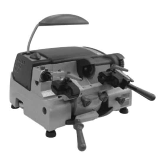
OTOR ON SWITCH SPEED COMMUTATOR On the top left-hand side there is a switch for starting the motor at the required speed. • LLUMINATION The lamp is fixed and it illuminates the work zone to be used perfectly. Copyright Silca 2005... -
Page 9: Working Parts
M1- mobile clamp for bit/double bit and pump keys P - fixed clamp locking lever P1- mobile clamp locking lever R - lever for movement of mobile clamp S - locking lever for mobile clamp T - lamp U - brush V - chippings tray Copyright Silca 2005... -
Page 10: Technical Data
2 mm allen key 6 mm allen key fuse 5 Amp - rapid D300221ZZ D300226ZZ D310788ZZ 2,5 mm allen key Setting pins D300222ZZ D200470ZZ mm allen key Stop pins for 3 mm FIAM keys 2 pcs. D300223ZZ D400753ZZ Copyright Silca 2005... -
Page 11: Safety
5) Neon lamp 6) Cutter motor condenser 7) Commutator 8) Motor cut-out safety switch 9) Cutter motor 10) Motor ventilator W V U 3 2 1 brown black brown brown brown blue blue blue yellow/green black blue Copyright Silca 2005... -
Page 12: Transport
When the TECHNICA key cutting machine has been unpacked, place it directly on its workbench; this operation should be carried out by at least two people. Take care to lift the machine firmly holding the base, and no other part. Copyright Silca 2005... -
Page 13: Machine Installation And Preparation
- temperature: between +10 and +40˚C - relative humidity: approx 60% 3.5 Graphics (OFF) (speed 1) (speed 2) THE USE OF PROTECTIVE MOTOR START-UP COMMUTATOR 2 SPEED GOGGLES IS COMPULSORY Fig. 8 Copyright Silca 2005... -
Page 14: Regulation And Use Of The Machine
Clamp aligned for gauging and key-cutting operations for pump keys and keys with centre stop. Use the lever (S) to lock the right-hand clamp in a horizontal position. Rocker clamp for cutting bit/double bit keys (rounding off cuts). Release the right-hand clamp by lowering the lever (S). Copyright Silca 2005... -
Page 15: Checking And Gauging
If this is not so, loosen the screw (D2) and use a screwdriver to regulate the screw (D4) (fig. 14, page 12) until the ideal situation is reached. Fig. 12 Fig. 13 Copyright Silca 2005... -
Page 16: Depth Gauging
11) After having locked ring nut (N) turn the other ring nut (N1) until the red indicator is aligned with the notch on the tracer point. Note: when the 2 ring nuts are turned together, each notch moves them 0.05 mm. Fig. 15 Copyright Silca 2005... -
Page 17: Cutting Operations 1
5) Cut the whole bit and remove any burrs at the end of the cutting operation. 6) For double bit keys, turn both keys and repeat the operations described above. 7) When the cutting operation is complete, turn the switch to “0” and remove the keys. Fig. 16 Copyright Silca 2005... -
Page 18: Cutting Short Keys
Any imprecision between the hole axis and the stem is additional to the normal tolerance for manual cutting. 2 mm (max.) 1,5 mm (min.) 17 mm (max.) 15 mm (max.) Fig. 18 Copyright Silca 2005... -
Page 19: Cutting Keys With Centre Stop
3) Use the lever (L) to pull the carriage back and go to another cutting position, then continue as in point 2 above. 4) When the cutting operation is complete, turn the switch to “0” and remove the keys. Fig. 19 Copyright Silca 2005... -
Page 20: Cutting Pump Keys
6) Check the bit edges and rectify, if necessary. 7) When the cutting operation is complete, turn the switch to “0” and remove the keys. Fig. 20 Fig. 21 Fig. 22 Copyright Silca 2005... -
Page 21: Maintenance
3) Fit the new tracer point, pushing all the way in. Ensure that the seat is clean. 4) Tighten the screw (D3). 5) Re-calibrate the machine, following the procedure described in chap. 4.4.2, page 12. Fig. 24 Copyright Silca 2005... -
Page 22: Replacing The Cutter
2) Place the locking bar into the special hole in the cutter shaft (fig. 27). 3) Use the Allen wrench to loosen the screw (U1) holding the brush in place (fig. 27). 4) Replace the brush and tighten the screw (U1) with the Allen wrench. Fig. 27 Copyright Silca 2005... -
Page 23: Belt Replacement And/Or Tensioning - Belt Tightening Pulley Replacement
13) Replace the belt cover and secure with the screw (W2). 14) Replace the top cover and secure with the 4 screws (V1). 15) Replace the cutter shield and secure with the 3 screws (C2). 16) Replace the swarf tray. Fig. 30 Copyright Silca 2005... -
Page 24: Belt Tightening Pulley Replacement
7) Fit the new switch properly, taking care to secure it well (tabs). 8) Reconnect the various connectors [1] [2] [3] [4]. 9) Replace the bottom plate and fix with the 7 screws (N1). 10) Replace the machine upright on the bench and fit the swarf tray. Fig. 32 Copyright Silca 2005... -
Page 25: Replacing The Fuses
3) Make sure the plate is in place and replace the spring. 4) Tension the spring by tightening the grub screw (F1). 5) Fit the carriage so that it butts against its mechanical stop, then secure with the 2 knobs (F) (chap. 5.2). Fig. 35 Copyright Silca 2005... -
Page 26: Condenser (Motor) And/Or Feeder (Lamp) Replacement
4) Place the new reactor into its seat and secure with the 2 screws (K1). 5) Replace the bottom protective plate and secure with the 7 screws (N1) (fig. 36). 6) Replace the machine upright on the bench and fit the swarf tray. Fig. 37 Copyright Silca 2005... -
Page 27: Speed Commutator
5) Push the switch into its seat and secure with the 2 screws (B2). 6) Replace the top cover and secure with the 4 screws (V1). 7) Replace the commutator knob (B). Fig. 39 Fig. 40 Fig. 41 Copyright Silca 2005... -
Page 28: Motor Replacement
25) Replace the belt cover and secure with the screw (W2). 26) Replace the top cover and secure with the 4 screws (V1). 27) Replace the cutter shield and secure with the 3 screws (C2). 28) Replace the swarf tray. 3 4 5 Fig. 42 Copyright Silca 2005... - Page 29 Technica Operating manual - English Fig. 43 Fig. 44 Copyright Silca 2005...
-
Page 30: Decommissioning
• For information about the collection system for such appliances please contact SILCA S.p.A. or another subject registered in the various National Rolls for other countries in the European Union. Household waste (or of similar origin) can be included in the separate collection system for urban waste. -
Page 31: After Sales Service
7.1 How to request service The guarantee attached to TECHNICA key-cutting machines ensures free repairs or replacements of faulty parts within twelve months of purchase. All other service calls must be arranged by the customer with Silca or with a Silca service centre. - Page 33 Vittorio Veneto VITTORIO VENETO 11/11/2005 CE DECLARATION OF MACHINE COMPLIANCE SILCA S.p.A. - VIA PODGORA 20 ( Z.I.) 31029 VITTORIO VENETO (TV) - (ITALY) TEL. 0438 9136 - FAX. 0438 913800 Declares under its own responsibility that the Key-cutting machine model...
- Page 34 SILCA S.p.A. Via Podgora, 20 (Z.I.) 31029 VITTORIO VENETO (TV) Tel. 0438 9136 Fax 0438 913800 www.silca.it Member of the Kaba Group...
Need help?
Do you have a question about the D429724XA and is the answer not in the manual?
Questions and answers