Sign In
Upload
Download
Table of Contents
Contents
Add to my manuals
Delete from my manuals
Share
URL of this page:
HTML Link:
Bookmark this page
Add
Manual will be automatically added to "My Manuals"
Print this page
×
Bookmark added
×
Added to my manuals
Manuals
Brands
Silca Manuals
Cutter
Matrix Evo
Operating manual
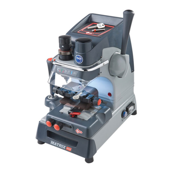
Silca Matrix Evo Operating Manual
Hide thumbs
1
2
Table Of Contents
3
4
5
6
7
8
9
10
11
12
13
14
15
16
17
18
19
20
21
22
23
24
25
26
27
28
29
30
31
32
33
34
35
36
37
38
39
40
41
42
43
44
45
46
47
48
49
50
51
52
page
of
52
Go
/
52
Contents
Table of Contents
Bookmarks
Table of Contents
Table of Contents
Use of the Manual
Glossary Symbols-Terminology
General Warnings
1 Machine Description
2 WORKING PARTS - Matrix PRO
3 WORKING PARTS - Matrix EVO
4 Accessories Provided
Technical Data
5 Electric Diagram
6 Handling
Packing
Transport
Unpacking
Handling the Machine
7 Machine Installation and Preparation
Checking for Damage
Environmental Conditions
Positioning
Safety Devices
Work Station Description
Starting the Key-Cutting Machine
Starting the Motor
Cutter Motor on Warning Light
Led Lamp (Matrix Pro Version)
Led Lamp (Matrix Evo Version)
8 Machine Calibration and Regulation
Fitting and Removing Tools
Micrometer Gauge
Calibration / Tool Alignment
Tracer Point Spring
Carriage Spring for Laser Keys
Clamps
The Clamp Unit Has Several Seats Dedicated to the Positioning of Different Types of Keys
9 Cutting
Fitting Keys
Key Stop
Cutting Dimple Keys
Back Cuts
Inclined Cuts
Cutting Laser Type Keys
Cutting Laser Keys with Narrow Stems
Cutting Fichet Type Keys (H Profile)
Cutting Tubular Keys (MATRIX PRO Version)
10 Maintenance
Tightening and Replacing the Belt
Removing the Upper Front Unit
Replacing the Rollbar
Replacing the Transparent Safety Shield
Replacing the Lamp
Adjusting/Replacing the Vertical Carriage Spring
Checking and Replacing Fuses
Replacing the Calibration Key Pad Electronic Circuit Board
Replacing the Condenser
Replacing the Motor
Replacing the Transformer
Replacing Switches: Master and Motor on
Aligning/Calibrating the Clamp
Control Alignment Left-Hand Stationary Jaws
Control Alignment Right-Hand Stationary Jaws
Replacing the Jaws
Replacing the Left-Hand Stationary Jaws
Replacing Right-Hand Stationary Jaws
Replacing Left-Hand Clamp Mobile Jaw
Replacing Right-Hand Mobile Clamp Jaw
11 Disposal
12 After-Sales Service
How to Apply for After-Sales Service
Advertisement
Quick Links
1
Working Parts - Matrix Pro
2
Machine Calibration and Regulation
3
Calibration / Tool Alignment
Download this manual
Operating Manual
Original Instructions
D439848XA
vers. 4
EN
Table of
Contents
Previous
Page
Next
Page
1
2
3
4
5
Advertisement
Table of Contents
Need help?
Do you have a question about the Matrix Evo and is the answer not in the manual?
Ask a question
Questions and answers
Related Manuals for Silca Matrix Evo
Cutter Silca Technica EU Operating Manual
Key-cutting machine (30 pages)
Cutter Silca Bravo Series Operating Manual
(42 pages)
Cutter Silca Unocode 299 Operating Manual
Electronic key-cutting machine (67 pages)
Cutter Silca FUTURA PRO ONE Quick Start Manual
(2 pages)
Cutter Silca FUTURA PRO Quick Start Manual
(2 pages)
Cutter Silca Futura Auto Operating Manual
(43 pages)
Cutter silca REKORD Operating Manual
(35 pages)
Cutter Silca Unocode PRO Operating Manual
(100 pages)
Cutter Silca Triax Pro Operating Manual
(114 pages)
Cutter Silca OPERA IV Operating Manual
Key-cutting machine (28 pages)
Cutter Silca UC 199 Operating Manual
Key cutter machine (107 pages)
Cutter Silca Unocode 399 Plus Operating Manual
(93 pages)
Cutter Silca OLYMPIC Operating Manual
Key-cutting machine (25 pages)
Cutter Silca Idea Operating Manual
Key-cutting machine (152 pages)
This manual is also suitable for:
Matrix pro
Matrix evo s
Matrix pro s
Table of Contents
Print
Rename the bookmark
Delete bookmark?
Delete from my manuals?
Login
Sign In
OR
Sign in with Facebook
Sign in with Google
Upload manual
Upload from disk
Upload from URL


Need help?
Do you have a question about the Matrix Evo and is the answer not in the manual?
Questions and answers