Sign In
Upload
Manuals
Brands
SICK Manuals
Measuring Instruments
GM32 Series
SICK GM32 Series Manuals
Manuals and User Guides for SICK GM32 Series. We have
4
SICK GM32 Series manuals available for free PDF download: Technical Information, Operating Instructions Manual
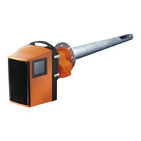
SICK GM32 Series Technical Information (98 pages)
In-situ Gas Analyzer Measuring Probe Version
Brand:
SICK
| Category:
Measuring Instruments
| Size: 4 MB
Table of Contents
Table of Contents
4
1 General Information
7
Responsibility of User
8
Designated Users
8
Special Local Conditions
8
2 Product Description (Details)
9
Measuring Method
10
Optics Layout and Functional Principle
10
Signal Evaluation
11
Zero Adjust (Description)
12
Reference Cycle (Description)
12
Reference Cycle Sequence
12
Check Cycle (Description)
12
Control Elements
12
Check Cycle (Function)
13
Wavelength Scale Monitoring
13
Resolution Drift Monitoring
13
Absorption Drift Monitoring
13
Determining the Zero and Reference Point
14
Monitoring the Cell no Filling
14
Summary
15
Events and Signals Output
15
Check Cycle Signals
15
Maintenance Request Signal
15
Zero and Reference Point Level Output
15
Contamination Compensation
16
Monitoring Contamination
16
Automatic Adjustment with Alignment
16
Measuring Probe in Detail
17
3 CAN Connection
21
GM32 CAN Connection
22
SCU Connection (Overview)
23
Connecting the GM32 to the CAN Bus and to the SCU
24
Settings in GM32
25
Settings in the SCU
25
Mapping Table
26
4 Operation (Specialist Menus)
29
SOPAS ET (Description)
30
Menu Tree (in SOPAS ET)
31
Changing the User Level
32
Measured Values
33
Bargraph Measured Values
33
Parameters
34
Device Parameters
34
Spectrometer
35
Coefficients
35
Coefficients Boxmeasuring
36
Adjustment Sensor
36
Logbook
37
Analog Outputs
38
Analog Inputs
38
Digital Inputs
39
Digital Outputs
39
Hardware Map
41
Adjustment
42
Alignment
42
Zero Adjust (Service Level Only)
43
Boxmeasuring (Service Level Only)
44
Diagnosis
45
Device Information
45
Logbook
45
Check Cycle
47
Sensor Values
47
Temperature Unit
50
Spectra
51
Maintenance
56
Operating Mode Switch
56
Lamp Hour Meter
56
Save EEPROM
57
Load EEPROM
57
Start-Up Assistant
57
Program/Data Structure ("Firmware", "Device Description File")
58
Sequence of Settings and File Transfers
58
Setting the GM32 Analyzer/Scu IP Address
59
Updating the Firmware (GM32 Analyzer/Scu)
60
Loading the Device Description File ("Make Available to SOPAS ET")
61
Saving and Loading Parameters (Device Data)
62
Loading Parameters Changed in SOPAS ET to the GM32 Analyzer/Scu
62
Saving Parameters (GM32 Analyzer/Scu) to an External Data Medium
63
Loading Parameters from an External Data Medium to the GM32 Analyzer
63
Scu
63
Loading Data Files from the Device
63
5 Maintenance
65
Zero Adjust (Zero Point Check)
66
Procedure
66
Boxmeasuring
68
Preparing the Filter Box
69
Determining the Necessary Test Gas Concentration
71
Procedure
72
Test Gas Feeding (for GPP Measuring Probe)
76
One-Off Initial Measurement - Determining the Test Gas Pressure
77
Manual Test Gas Feeding
78
Using Mixed Gases as Test Gases
78
Fitting and Removing the Power Supply Unit of the Connection Unit
79
6 Shutting Down/Restarting
81
Qualification Requirements
82
Shutting down
82
Equipment Required
82
Shutdown
83
Removing from the Sample Gas Duct
83
Disconnecting the Purge Air Connection
84
Putting the Purge Air Unit out of Operation
85
Further Components on the Measuring Point
86
Connection Unit and Cabling
86
Conservation Measures, Correct Storage and Transport
87
Preparing for Restarting
89
New Measuring Task
89
Previous Measuring Task
89
Purge Air Unit Maintenance
89
7 Annex
91
Commissioning Checklist
92
Advertisement
SICK GM32 Series Operating Instructions Manual (80 pages)
In-situ Gas Analyzer, Measuring Probe Version
Brand:
SICK
| Category:
Measuring Instruments
| Size: 5 MB
Table of Contents
Table of Contents
3
1 About this Document
6
Symbols and Document Conventions
6
Warning Symbols
6
Warning Levels / Signal Words
6
Information Symbols
7
Main Instructions for Operation
7
Intended Use
7
Purpose of the Device
7
Product Identification
7
Responsibility of User
7
Additional Documentation/Information
8
2 Product Description
9
Device Versions
9
TRS Calculation
10
Device Variants
10
Options
11
SOPAS ET (PC Program)
11
Reference Cycle
11
Check Cycle
11
GM32 Design
13
Measuring Probe
13
Purge Air Unit (for GMP Measuring Probe)
13
Light Sources
14
3 Preparing the Gas Duct Side
15
Preparing the Sampling Point
15
Checking the Scope of Delivery
15
Overview of the Installation Steps (Duct-Side Work)
16
Work Steps (Overview)
17
Installing the Flange with Tube on the Gas Duct
17
Installing the Connection Unit
18
Installing the Purge Air Unit (for GMP Probe)
18
Laying the Electrical Connection Lines
19
General Information
21
Connecting I/O Interfaces (Option)
21
Default Values for Interfaces
22
Laying the Electrical Connection Lines to the SR-Unit
23
Preparing the Power Supply
24
4 Start-Up
25
Necessary Technical Knowledge for Start-Up
25
Required Material (Not Included in the Scope of Delivery)
27
Overview of Assembly Steps
28
Transport Safety Devices
29
Installing the Device Flange on the Purge Air Fixture
30
Aligning the Measuring Probe in Flow Direction
31
When the Probe Alignment Has to be Set
31
For the GPP Probe: Electrical Connection
32
Electrical Connection of the SR-Unit
33
Switching on the Power Supply of the GM32
33
For GMP Probe: Start-Up of the Purge Air Supply
33
Installing the Measuring Probe in the Gas Duct
34
Installing the SR-Unit on the Device Flange
36
Optical Fine Alignment of the SR-Unit
36
Opc
37
OPC Interface
38
Installing Weatherproof Covers (Option)
39
5 Operation
41
Recognizing an Unsafe Operating State
41
Operator Panel
42
Status Indicators (Leds)
42
Button Assignment
42
Contrast Setting
42
Language
43
Menu Tree
43
Diagnosis
44
Check Cycle
45
Alignment Check (Automatic Optical Alignment Check; Option)
45
Adjustments
45
Maintenance
47
6 Maintenance
48
Maintenance Plan (Operator)
48
Recommended Expendable and Wearing Parts for 2 Years Operation
48
Preparation Work
48
Swiveling out and Removing the SR-Unit
49
Visual Inspection
49
Cleaning the Window
50
Checking and Replacing the Desiccant Cartridges
50
Replacing the Sender Lamp and LED for GM32 Lownox
51
Tools Required
51
Sender Lamp with LED Unit
51
Cleaning the Purge Air Unit
53
7 Clearing Malfunctions
54
Safety Instructions When Clearing Malfunctions
54
Error Diagnosis Tables
55
Device Not Functioning
55
Measured Values Clearly Incorrect
55
Sample Gas Penetrating
55
Corrosion on Probe or Flanges
56
Measured Value Blinks
56
Error Messages
56
Example of an Error Message
56
Error Messages
57
Inadequate Purge Air Supply (for GMP Probe)
61
Malfunctions on the Connection Unit
61
8 Shutdown
62
Disassembly
62
Storage
63
Environmentally Compatible Disposal / Recycling
63
9 Specifications
64
Conformities
64
Electrical Protection
64
System: GM32
65
System GM32 Standard
65
System GM32 TRS-PE
66
Sender/Receiver Unit
67
Open Measuring Probe (GMP)
67
Gas-Testable Measuring Probe (GPP)
67
Connection Unit
68
Modbus Register Mapping
69
Mapping of GM32 Measuring Components
69
Mapping for GM32 in General
70
Mapping of Modbus Input Values
71
Bitmap Table "Failure
72
Bitmap Table "Maintenance Request
72
Bitmap Table Function "Check" and "Out of Specification
72
Bitmap Table "Extended
73
Dimensions
74
SICK GM32 Series Operating Instructions Manual (76 pages)
In-situ Gas Analyzer Measuring Probe Version
Brand:
SICK
| Category:
Measuring Instruments
| Size: 4 MB
Table of Contents
Table of Contents
4
1 Important Information
7
Main Instructions for Operation
8
Intended Use
8
Purpose of the Device
8
Responsibility of User
8
Additional Documentation/Information
9
2 Product Description
11
Product Identification
12
Product Description
12
Device Variants
12
Options
12
SOPAS ET (PC Program)
13
Reference Cycle
13
Check Cycle
13
Design of GM32
15
Measuring Probe
15
Purge Air Unit (for GMP Measuring Probe)
15
3 Preparation on the Gas Duct Side
17
Preparation of Sampling Point
18
Checking the Scope of Delivery
18
Overview of the Installation Steps (Duct-Side Work)
19
Work Steps (Overview)
19
Installing the "Flange with Tube" on the Gas Duct
20
Installing the Connection Unit
20
Installing the Purge Air Unit (for GMP Probe)
21
Laying the Electrical Connection Lines
22
General Information
23
Connecting I/O Interfaces (Option)
23
Laying the Electrical Connection Lines to the SR-Unit
23
Preparing the Power Supply
24
4 Start-Up
25
Necessary Technical Knowledge for Start-Up
26
Required Material (Not Included in the Scope of Delivery)
26
Overview of Assembly Steps
27
Transport Safety Devices
27
Installing the Device Flange on the Purge Air Fixture
29
Aligning the Measuring Probe in Flow Direction
30
When the Probe Alignment Has to be Set
30
For the GPP Probe: Electric Connection
31
SR-Unit Electric Connection
32
Switching on the Power Supply of the GM32
32
For GMP Probe: Start-Up of the Purge Air Supply
33
Installing the Measuring Probe in the Gas Duct
34
Installing the SR-Unit on the Device Flange
35
Optical Fine Alignment of the SR-Unit
35
5 Operation
37
Recognition of an Unsafe Operational State
38
Operator Panel (for the "Pro" Variant)
39
Status Indicators (Leds)
39
Assignment of Buttons
39
Contrast Setting
39
Language Setting
40
Menu Tree
40
Diagnosis
40
Alignment Check (Automatic Optical Alignment) (Option)
41
Adjustments
42
Maintenance
44
6 Putting out of Operation
45
Putting out of Operation
46
Disassembly
46
Storage
47
Environmentally Compatible Disposal / Recycling
47
7 Maintenance
49
Maintenance Plan (Operator)
50
Recommended Expendable and Wearing Parts for 2 Years Operation
50
Preparation Work
51
Swiveling out and Removing the SR-Unit
51
Visual Inspection
52
Cleaning the Window
52
Replacing the Sender Lamp
53
Checking and Replacing the Drying Agent Cartridges
54
Cleaning the Purge Air Unit
55
8 Clearing Malfunctions
57
General Hazard Caused by Electrical Voltage
58
Measured Value Blinks
58
Error Messages
59
Example of an Error Message
59
Error Messages
60
Inadequate Purge Air Supply (for GMP Probe)
64
Malfunctions on the Connection Unit
64
9 Specifications
65
Conformities
66
Electrical Protection
66
Technical Data
67
Optical Alignment
73
Advertisement
SICK GM32 Series Operating Instructions Manual (81 pages)
In-situ Gas Analyzer
Brand:
SICK
| Category:
Measuring Instruments
| Size: 5 MB
Table of Contents
About this Document
6
Information Symbols
7
Product Identification
8
Product Description
9
Options
10
GM32 Design
12
Light Sources
13
Preparing the Gas Duct Side
14
Overview of the Installation Steps (Duct-Side Work)
15
Installing the "Flanges with Tube" on the Gas Duct
16
Installing the Connection Unit
18
Laying the Electrical Connection Lines
19
General Information
21
Default Values for Interfaces
22
Laying the Electrical Connection Lines to the SR-Unit
23
Preparing the Power Supply
24
Start-Up
25
Required Material
27
Overview of Assembly Steps
28
Transport Safety Devices
29
Installing the Purge Air Fixtures on the Flange with Tube
30
Installing the Device Flange on the Purge Air Fixture
31
Aligning the Device Flanges and Purge Air Fixtures
32
Electrical Connection of the SR-Unit and Reflector Unit
34
Start-Up of the Purge Air Supply
35
Installing the SR-Unit and Reflector Unit on the Device Flange
36
OPC Interface
38
Installing Weatherproof Covers (Option)
39
Operation
41
Operator Panel
42
Language
43
Diagnosis
44
Check Cycle
45
Adjustments
46
Maintenance
47
Maintenance
48
Swiveling out and Removing the SR-Unit
49
Visual Inspection
50
Replacing the Sender Lamp and LED GM32LN
51
Cleaning the Purge Air Unit
53
Clearing Malfunctions
54
Error Diagnosis Tables
55
Sample Gas Penetrating
56
Error Messages
57
Inadequate Purge Air Supply
61
Shutdown
62
Storage
63
Technical Data
64
System: GM32
65
Sender/Receiver Unit
66
Characteristic Data for Electric Isolation
67
Mapping for GM32 in General
69
Mapping of Modbus Input Values
70
Bitmap Table "Failure
71
Bitmap Table Function "Check" and "Out of Specification
72
Dimensions
73
Index
78
Advertisement
Related Products
SICK GM32 EX
SICK GM32-1
SICK GM32-4
SICK GM32-5
SICK GM32-6
SICK GM32-8
SICK GM32-7
SICK GM32-9
SICK GM32-TRS-PE02
SICK GM32-TRS-PE01
SICK Categories
Accessories
Security Sensors
Measuring Instruments
Scanner
Barcode Reader
More SICK Manuals
Login
Sign In
OR
Sign in with Facebook
Sign in with Google
Upload manual
Upload from disk
Upload from URL