Table of Contents
Advertisement
Quick Links
OPERATION MANUAL
DIAGNOSTIC ULTRASOUND SYSTEM
MODEL TUS-A500
[FUNDAMENTALS]
(2B771-004EN*M)
In the USA, federal law restricts this device to sale by
or on the order of a physician.
IMPORTANT!
Read and understand this manual before operating
the equipment. After reading, keep this manual in
an easily accessible place.
TOSHIBA MEDICAL SYSTEMS CORPORATION 2010-2014
ALL RIGHTS RESERVED
FOR
CAUTION:
No. 2B771-004EN*M
Advertisement
Table of Contents

Related Manuals for Toshiba Aplio 500 TUS-A500

Summary of Contents for Toshiba Aplio 500 TUS-A500
- Page 1 In the USA, federal law restricts this device to sale by or on the order of a physician. IMPORTANT! Read and understand this manual before operating the equipment. After reading, keep this manual in an easily accessible place. TOSHIBA MEDICAL SYSTEMS CORPORATION 2010-2014 ALL RIGHTS RESERVED...
- Page 2 Cleanisept® is a registered trademark of Dr. Schumacher GmbH. Java is a registered trademark of Oracle and/or its affiliates. APLIO, Dynamic Flow, ApliPure, MicroPure, and TwinView are trademarks of Toshiba Medical Systems Corporation. This manual may include trademarks or registered trademarks of other companies.
- Page 3 Indicates reference information that enables more efficient use of the equipment. Operation Manuals A TOSHIBA service person or instructor will explain the basic operating procedures for this system at the time of delivery. However, read this operation manual carefully before using the system in order to understand the detailed operating procedures, functions, performance, and maintenance procedures.
- Page 4 Switch Configuration The descriptions in this operation manual are based on the standard switch configuration. If the switch configuration has been changed, the differences between the current configuration and the standard configuration must be understood before use. The layout, shapes, labels, and icons of the switches on the touch panel can be changed. All the figures of touch panel and switches in this manual are examples and may differ from the actual display.
-
Page 5: Table Of Contents
Table of Contents Organization of the Operation Manuals ............U-1 Intended Use ..................1-1 Intended Medical Use ................1-1 Intended Patient Information ............1-1 User Profile ....................1-1 Operating Principles ................1-1 General Safety Information ........... 2-1 Meaning of Signal Words .............. - Page 6 General Information on Usage and Maintenance ..................3-1 Use Conditions ................4-1 Power and Environmental Requirements ......4-1 Environmentally Friendly Usage and Maintenance Management ............... 4-2 System Configuration ............5-1 Standard Configuration ..............5-1 List of Optional Units ................5-1 Compatible Peripheral Devices ............
- Page 7 7.2.2 Connecting/Disconnecting the transducer ........7-4 Adjusting the Main Panel ..............7-6 Adjusting the Monitor ................7-8 7.4.1 Locking and releasing the monitor ............7-8 7.4.2 Adjusting the angle of the monitor ............7-9 7.4.3 Adjusting the monitor display ............... 7-10 Checks Before and After Use ........
- Page 8 10.3 Thumbnail Display ................10-4 Starting an Examination ..........11-1 11.1 Entering and Saving Data on the [Patient Registration] Screen ............11-2 Reference Signal Display ..........12-1 12.1 Reference Signal Panel ..............12-4 12.2 Installing the Reference Signal Sensor ........ 12-5 12.3 Adjusting Reference Signals ............
- Page 9 14.1.2 Adjustment using the main panel ............14-2 14.1.3 Adjustments using the touch panel ............ 14-5 14.1.4 Selection of image zooming method ..........14-8 14.1.5 2D mode quick scan ................14-10 14.1.6 Trapezoid scan ..................14-12 14.2 M Mode ....................... 14-13 14.2.1 M display layout ..................
- Page 10 14.7 Doppler Mode ..................14-34 14.7.1 Doppler display layout ................14-34 14.7.2 Adjustment using the main panel ............14-35 14.7.3 Adjustments using the touch panel ..........14-38 Cine Function ................. 15-1 15.1 Overview ..................... 15-1 15.2 Cine Operations ..................15-1 Body Mark ...................
- Page 11 19.2.1 Operations using the touch panel ............19-3 19.2.2 Snapshot Clips .................... 19-4 19.2.3 Cine Clips (storage of cine image data) ..........19-6 19.2.4 Setting of the storage format (for retrospective storage) ..19-8 19.3 File Handling for Image Data ............
- Page 12 23.1 External Dimensions and Mass ..........23-1 23.2 Essential Performance of This System ......... 23-1 23.3 Conformance Standards ..............23-2 23.4 Safety Classification ................23-3 23.5 Accuracy of Measurement ............. 23-4 Using MI/TI ..................24-1 24.1 Using MI/TI (Outside the USA and Canada) .......
- Page 13 24.2.10 References for MI/TI ................. 24-18 Guidance and Manufacturer's Declaration ..................25-1 Intellectual Property .............. 26-1 26.1 Availability of This Software and Related Documents Is Restricted..........26-1 26.2 Agreement for Microsoft Software ........... 26-1 26.3 Others ......................26-9 Indication of Year of Manufacture ......
-
Page 14: Intended Use
1. Intended Use Intended Medical Use (1) The intended use of this system is to visualize structures, characteristics, and dynamic processes within the human body using ultrasound and to provide image information for diagnosis. (2) This system provides high-quality ultrasound images in all its modes: 4D mode, 2D mode, M mode, CDI (Color Doppler Imaging) mode (blood-flow imaging), and Doppler mode (blood-flow spectrum). - Page 15 In 2D (B) mode imaging, the echo amplitudes are represented as brightness changes on the image display screen. Since the ultrasound beam attenuates in tissue, the degree of amplification required generally increases as depth increases. Regions of high reflection are displayed as brighter, while regions of low reflection appear darker. An M-mode image (cross-sectional image) can be displayed together with a 2D-mode image on the same screen through time-sharing control, allowing the user to perform M-mode diagnosis while observing a 2D-mode image.
-
Page 16: General Safety Information
2. General Safety Information This section describes the general precautions and details that must be observed when using this system. Precautions related to specific operations are described in the corresponding sections. When using the system, be sure to also read the precautions in the operation manual Measurements volume and the operation manual Applications volume, respectively. -
Page 17: Ensuring The Safety Of Patients And Operators
If the surface temperature of the transducer becomes abnormally high, stop using the transducer and contact your TOSHIBA service representative. 3. This device is contraindicated for ophthalmic use or any application that causes the acoustic beam to pass through the eye. -
Page 18: Preventing Electric Shocks, Fires, And Power Supply Interruptions
Stop using it immediately and contact your Toshiba service representative. Continuing to use the system may result in electric shock, fire, or interruption of power supply. - Page 19 WARNING: 6. Do not connect any devices other than those specified by TOSHIBA to the USB connector or other connectors on the system. 7. Do not connect to the system transducers other than those specified by TOSHIBA, to prevent accidents such as fire.
-
Page 20: Chemical Hazard
Observe the following precautions to ensure EMC. WARNING: The use of transducers and cables other than those specified, with the exception of transducers and cables sold by Toshiba Medical Systems Corporation as replacement parts, may result in increased emissions or reduced system performance. No. 2B771-004EN*M... -
Page 21: Acoustic Power
CAUTION: Malfunctions due to radio waves (1) This system may malfunction due to electromagnetic influence from electric scalpels, high-frequency therapy equipment, or other devices that generate high frequencies. (2) The use of radio-wave-emitting devices near this unit may interfere with its operation. Devices that generate radio waves, such as cellular phones, transceivers, and radio- controlled toys, must not be brought into the room where this unit is installed and must never be used near the unit. -
Page 22: Preventing System Malfunctions
Preventing System Malfunctions Observe the following precautions to prevent system malfunctions. CAUTION: 1. Only software authorized by TOSHIBA should be installed in this system. Otherwise, a system failure or malfunction may result. 2. If the system is infected with malware (malicious software,... - Page 23 TOSHIBA service representative. 7. If the main power switch on the power panel or circuit protector trips, be sure to consult your TOSHIBA service representative. If the main power switch is turned ON again before the problem is corrected, the system or a connected device may sustain further damage.
-
Page 24: Handling Patient And Image Data
Handling Patient and Image Data To prevent incorrect diagnosis and reexaminations, observe the following precautions when handling data. CAUTION: 1. Entering patient data Before starting an examination for a new patient, confirm that the patient ID matches the patient to be examined. If images are recorded with an incorrect patient ID, the data may be mixed up with that for another patient, resulting in incorrect diagnosis. - Page 25 Warning labels on systems complying with the European Directive 93/42/EEC Label Meaning <1> Urges caution related to handling of the transducers. For handling of the transducers, refer to the transducers' operation manual. <2> Cautions that the MI/TI must be controlled as low as reasonably achievable.
- Page 26 Warning labels on other systems Label Meaning <1> Cautions that restrict this device to sale by or on the order of a physician. (USA/Canada only) <2> Urges caution related to handling of the transducers. <3> (a) Cautions that the MI/TI must be controlled as low as reasonably achievable.
-
Page 27: Regulatory Labels
Label Meaning <7> Cautions that the system must not be used around flammable gases. <8> Cautions that hands may be caught when the height of the main panel is adjusted. <<Warning labels for options>> Item Label Meaning Cautions that the Fusion function (option) must not be used for patients who use electronic life- support devices (for example, a cardiac Fusion unit... -
Page 28: Precautions Concerning Clinical Examination Techniques
2.12 Precautions Concerning Clinical Examination Techniques (1) This operation manual is intended for users who are well-versed in the principles and basic techniques of ultrasound. (2) This system must be used only by medical personnel fully trained in clinical examination techniques. (3) This operation manual does not describe clinical examination techniques. -
Page 29: General Information On Usage And Maintenance
Important data must be backed up on external recording media such as clinical records, notebooks, floppy disks, or magnetic tapes. TOSHIBA shall not be liable for loss of data stored in the memory of this system caused by operator error or accidents. - Page 30 TOSHIBA shall not be liable for any error or malfunction that results from use of a transducer other than that specified by TOSHIBA. On the occasion of change of the administrator or manager for this system, be sure to hand over this operation manual.
- Page 31 NOTE: Perchlorate Material - special handling may apply. See http://www.dtsc.ca.gov/hazardouswaste/perchlorate/ This is applicable to California, USA, only. This system shall be connected to a network only if security measures against malware infection have been established for the network. Expected service life The expected service life is 7 years if the specified maintenance and inspection procedures are performed.
-
Page 32: Use Conditions
4. Use Conditions Power and Environmental Requirements Item Specifications 120 VAC 10% Power Line voltage 220 to 240 VAC 10% Europe 110 to 120 VAC 10% Other 1 220 to 240 VAC 10% Other 2 Line frequency 50 Hz to 60 Hz Power consumption 1440 VA Europe... -
Page 33: Environmentally Friendly Usage And Maintenance Management
Environmentally Friendly Usage and Maintenance Management Observe the following to keep environmental impact to a minimum. (1) Turn the system power OFF when the system is not in use. (2) When the system is not to be used for an extended period of time, turn OFF the main power switch on the power panel and disconnect the power plug from the outlet. -
Page 34: System Configuration
5. System Configuration Standard Configuration (1) Main unit of the system (2) Accessories Operation manuals Cables Transducer holder Gel holder List of Optional Units The following optional units are available with this system. Item Model CW unit UICW-A500A Reference signal unit UJUR-A500A (Except for USA) -
Page 35: Compatible Peripheral Devices
Europe) BD-X201ME (PAL: JVC, for Europe) * It may not be possible to use some of the peripheral devices listed above depending on the power conditions of the country. For details, contact your TOSHIBA service representative. External Storage Devices USB flash drives and barcode readers can be connected to this system. -
Page 36: List Of Optional Software
List of Optional Software The following optional software is available with this system. Item Model Realtime ASQ kit* USAS-A500A, USAS-A500A/EL Smart Fusion kit USFN-A500A, USFN-A500A/EL Fly Thru. kit USFT-A500A, USFT-A500A/EL Elastography kit USEL-A500A, USEL-A500A/EL 2D Wall Motion Tracking kit USWT-A500A, USWT-A500A/EL MicroPure USMP-A500A, USMP-A500A/EL CHI-Q kit... -
Page 37: List Of Available Transducers
List of Available Transducers The following transducers are available with this system. Transducer name Principal use PST-25BT Cardiac, pediatric, abdominal, adult cephalic, neonatal cephalic PST-30BT Cardiac, abdominal, adult cephalic, neonatal cephalic PST-50BT Cardiac, pediatric, and neonatal cephalic PST-65AT Cardiac, neonatal cephalic, pediatric PVT-350BTP Abdominal PVT-375BT... - Page 38 2D mode CHI mode Dynamic Elasto- Precision Transducer Power Apli- Micro- Flow graphy imaging Pulse Pulse name mode mode mode mode mode mode mode Pure Pure Dynamic mode mode Fund. Subtract Subtract Flow PST-25BT ...
- Page 39 2D mode CHI mode Dynamic Elasto- Precision Transducer Power Apli- Micro- Flow graphy imaging Pulse Pulse name mode mode mode mode mode mode mode Pure Pure Dynamic mode mode Fund. Subtract Subtract Flow PLT-1204BX ...
-
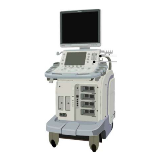
Page 40: Names And Functions Of Each Section
6. Names and Functions of Each Section Name of Each Section Systems with the main power switch on the rear No. 2B771-004EN*M... - Page 41 Systems with the main power switch on the side No. 2B771-004EN*M...
-
Page 42: Main Panel
It is also possible to change the positions of switches related to measurements, modes, or printer output (user function switches). To change the settings, contact your TOSHIBA service representative. CAUTION: Do not press several switches at the same time. Doing so may cause a malfunction. - Page 43 Switch name Function Turns the power ON/OFF. <1> Lights when the main power switch on the power panel is ON. <2> Goes out when the system is started up. Lights again when the system is shut down. Indicates the battery charge level. (Lights when the main power switch on the power panel is ON.) <3>...
- Page 44 Switch Function Starts up the [Patient Browser] screen. <16> Displays the previously acquired images or other data. Starts basic measurement mode. <17> Starts basic measurement mode. <18> Starts application measurement mode. <19> The function of this knob varies according to the mode. Measurement modes : Used to edit measurement results (for example, modification of an ellipse or a trace).
- Page 45 Switch Function Used to insert a body mark. <29> Turns display of the cursor ON/OFF. <30> Used to manipulate thumbnails. Used to switch trackball functions or specify the cursor position. <31> Pressing (in Freeze mode) : Returns to Cine mode (when Cine mode has been stopped due to a measurement operation, insertion of a body mark, insertion of an...
-
Page 46: Rear Panel
Rear Panel CAUTION: 1. Do not connect any devices other than those specified by TOSHIBA to the USB connector or other connectors on the system. 2. Do not connect any device that is not compliant with the required safety standards to the Ethernet port. Doing so might cause smoke generation or electric shock. -
Page 47: Symbols
Symbols The following symbols are used on this system. Note that the safety symbols are not shown here; they are shown in section 2 "General Safety Information". Symbol Description Functional ground Equipotential Main power switch OFF (AC power not supplied to system) Main power switch ON (AC power supplied to system) -
Page 48: Preparation For Examination
7. Preparation for Examination Moving and Installing the System WARNING: 1. Use the system only on a level floor. Do not place the system at a location where the slope is 5° or more. Doing so may result in the system falling over and causing an injury. - Page 49 (1) Before moving the system, be sure to release the caster locks. (a) Releasing all of the locks (b) Locking the caster for forward motion No. 2B771-004EN*M...
- Page 50 (2) Move the system to its installation position using the handle. (3) Lock the casters. No. 2B771-004EN*M...
-
Page 51: Handling And Connecting/Disconnecting The Transducer
Handling and Connecting/Disconnecting the Transducer 7.2.1 Handling the transducer CAUTION: 1. Do not subject the acoustic lens surface of the transducer to shock by hitting it against a hard object or dropping it on the floor. A failure affecting the safety or functionality of the transducer may result. 2. - Page 52 (2) Hang the transducer cable on the cable hanger or cable hook and place the transducer in the transducer holder. (3) Disconnect the transducer. No. 2B771-004EN*M...
-
Page 53: Adjusting The Main Panel
Adjusting the Main Panel CAUTION: When lowering the main panel, do not subject the cable hanger, cable hook, or transducer holder to any loads. Doing so may damage them. Adjusting the height of the main panel Hold the handle and press the vertical adjustment lever upward to raise or lower the height. - Page 54 Adjusting the horizontal position of the main panel (1) Pull the slide lever toward you to release its lock. (2) While pulling the slide lever, hold the handle, move the main panel to adjust the position, and then release the slide lever. The nearest position is locked when the lever is released.
-
Page 55: Adjusting The Monitor
Adjusting the Monitor CAUTION: Before moving the system, be sure to lock the movable section of the arm. Otherwise, the arm may move unexpectedly, resulting in an injury 7.4.1 Locking and releasing the monitor Locking and releasing the arm <<Locking the arm>> Lower the arm and turn the locking knob in the direction. -
Page 56: Adjusting The Angle Of The Monitor
7.4.2 Adjusting the angle of the monitor CAUTION: Do not touch the arm or the bottom of the monitor when adjusting the angle. Doing so may result in a hand injury. Moving the monitor vertically Moving the monitor horizontally No. 2B771-004EN*M... -
Page 57: Adjusting The Monitor Display
7.4.3 Adjusting the monitor display The brightness ( ) and the contrast ( ) can be adjusted as required using the buttons of the monitor. Displaying the adjustment menu Adjusting setting for the selected function NOTE: 1. To restore the factory default settings, press the [+] switch while holding down the [-] switch. -
Page 58: Checks Before And After Use
8. Checks Before and After Use In the interests of safety, it is the user's responsibility to carry out the following checks before and after using the system. Checks Before Turning ON the Power Perform the following checks before the system power is turned ON and after the system power is turned OFF. -
Page 59: Checks After Turning On The Power
Checks After Turning ON the Power Perform the following checks after the system power is turned ON and before the system power is turned OFF. Check item Check column There should be no abnormal sound, unusual smells, or overheating. No error message is displayed. - Page 60 IQ Report feature to save the image and the system information. <<Quick Procedure>> * If it is not possible to perform the operation above (the menu pane is not displayed, etc), perform the following operation. After the operation above is completed, contact your TOSHIBA service representative. No. 2B771-004EN*M...
-
Page 61: Turning The Power On/Off
9. Turning the Power ON/OFF WARNING: 1. Follow the instructions below regarding the power cable and plug. Insert the power plug only into a 3-pin (with protective grounding) medical electrical outlet. Do not connect the power cable to a 2-pin outlet using an adapter. -
Page 62: Connecting The Power Cable And The Protective Grounding
WARNING: 6. Do not connect the diagnostic ultrasound system to the same power outlet as another device. Doing so may cause the circuit breaker of the facility to trip, fuses to blow, or a fire or electric shock to occur. Connecting the Power Cable and the Protective Grounding (1) Connect the power plug to an outlet for medical equipment. - Page 63 Systems with the main power switch on the side No. 2B771-004EN*M...
-
Page 64: Turning On The Power
Turning ON the Power CAUTION: 1. Do not disconnect the power plug while the system is starting up. Doing so may cause the system to malfunction. 2. If either of the following phenomena occurs, press and hold down for 5 seconds or more to turn OFF the power of the system. ... - Page 65 NOTE: 1. For a cold boot, the time required to display the ultrasound image is usually approximately 3 minutes, but varies according to the system conditions. 2. If the registration screen is closed without registering any patient data, the 2D mode screen appears and the system enters Freeze mode. 3.
-
Page 66: Turning The Power Off
Turning the Power OFF CAUTION: 1. If the power cannot be turned OFF by the normal procedure, press and hold down for at least 5 seconds. If the power is still not turned OFF, turn OFF the main power switch on the power panel. These methods should not be used under normal conditions. - Page 67 NOTE: 1. If the system is unlikely to be used for a long period after the power is turned OFF, turn OFF the main power switch on the power panel and then unplug the power cable. 2. If the power cannot be turned OFF by following the normal procedures, 2D mode images may not be displayed when the system power is turned ON again.
- Page 68 NOTE: 5. When [Shutdown] is selected in the [Power Control] dialog during copying of patient data, transfer of patient data, or burning of patient data onto a CD/DVD, the following dialog is displayed. Item Function [Continue] <1> The current process is terminated and the shutdown process is started.
-
Page 69: Standby Mode
Standby Mode Standby mode is a function for suspending system operation without shutting down the system completely. CAUTION: 1. Do not set the system to Standby mode while printing or data saving or retrieval is in progress. Doing so may result in printing being terminated prematurely or in data being lost. - Page 70 The battery is intended to maintain the memory that stores system information required for the Standby function. The system cannot be started up using the battery only. Contact your TOSHIBA service representative for the battery kit. No. 2B771-004EN*M 9-10...
-
Page 71: Recovery From The Standby Status
NOTE: 5. Do not connect a USB device such as a flash drive to any of the external USB connectors (the system is provided with five USB connectors) when the system is in the Standby status. Doing so may result in the system not starting up normally from the Standby status. -
Page 72: Preparation For Use During Surgery Or For Emergency Cases
NOTE: 4. Directly after the system power is turned ON, the fan noise is initially loud but reduces after a short while. 5. Rarely, the message shown below may be displayed when an attempt is made to start the system from the Standby status. In such cases, select [OK] to close the message dialog. -
Page 73: Basic Screen And Menu
10. Basic Screen and Menu 10.1 Display of Various Data Items In addition to ultrasound images, various data items are displayed on the monitor. This section describes the screen display common to all modes. Refer to section 14 "Display and Operation in Each Mode" for the display specific to each mode. CAUTION: The free space on the hard disk is displayed at the top of the screen as "... -
Page 74: Displaying The Acoustic Power Data
CAUTION: When at the bottom left of the screen lights, it indicates that the system is ready to output images to the printer. Confirm that printing is completed by checking the printed images output from the printer. Note that if the next print operation is performed while this icon is lit, the next image is not printed. - Page 75 <Except for USA and Canada> Label Description Display location <1> [AP] Acoustic power Acoustic power display area The current transmission value (%) is displayed. <2> [TIS] Thermal index soft tissue Acoustic power display area Displayed as the calculated/estimated value for temperature increase in the soft tissues.
-
Page 76: Thumbnail Display
10.3 Thumbnail Display The thumbnails representing the data acquired in the current study are displayed in the thumbnail area. If previous study datasets for the same patient are present in the HDD, the study dates and exam types of these datasets are displayed in the study area. When a study date is clicked, the thumbnails representing the data for that date are displayed. -
Page 77: Starting An Examination
11. Starting an Examination CAUTION: 1. Before starting an examination for a new patient, confirm that the patient ID matches the patient to be examined. If images are recorded with an incorrect patient ID, the data may be mixed up with that for another patient, resulting in incorrect diagnosis. -
Page 78: Entering And Saving Data On The [Patient Registration] Screen
11.1 Entering and Saving Data on the [Patient Registration] Screen Start the exam by entering the patient details on the [Patient Registration] screen. <<Exam types>> Dropdown list item Exam type Dropdown list item Exam type [Abdomen] Abdomen general [Neo-Head] Neonatal head [Carotid] Carotid arteries [Neo-General]... - Page 79 NOTE: 1. The ID and name are displayed as "date + unique character string". If more than one system is used at the site, be sure to set a unique character string so that the system can be identified. 2. Do not enter a patient ID consisting of spaces only. The examination will not start.
- Page 80 7. The start function, which is normally assigned to , can be assigned to any other function key ( ) on the keyboard. To change key assignments, contact your TOSHIBA service representative. No. 2B771-004EN*M 11-4...
-
Page 81: Reference Signal Display
12. Reference Signal Display In the 2D, M, or M+2D (including Doppler) display modes, it is possible to display up to two types of reference signals of the electrocardiogram (ECG), the phonocardiogram (PCG), etc. This feature is optional. WARNING: 1. For protection against electric shock, confirm the following items before use: ... - Page 82 NOTE: Changing the lead type by changing the reference signal cable connections without using the ECG Lead function 1. The relationships between the lead wire colors of the reference signal cable and the electrode positions are described below. For regions other than the USA Electrode positions (lead I) Three electrode leads Electrode positions...
- Page 83 NOTE: Changing the lead type by changing the reference signal cable connections without using the ECG Lead function 1. The relationships between the lead wire colors of the reference signal cable and the electrode positions are described below. For the USA Electrode positions (lead I) Three electrode leads Electrode positions...
-
Page 84: Reference Signal Panel
IEC 60601-1 to [ECG DC IN] or [AUX]. Doing so may result in an electric shock. 2. If external signals are to be input to [ECG DC IN] or [AUX], contact your TOSHIBA service representative. The signal input level is restricted. Name Function <1>... -
Page 85: Installing The Reference Signal Sensor
12.2 Installing the Reference Signal Sensor (1) Connect the reference signal sensor cable to the reference signal panel while the system power is OFF. (2) Turn ON the power. (3) Set the sensor on the patient. 12.3 Adjusting Reference Signals (1) [PHYSIO] menu and reference signal display * Up to two reference signals can be displayed simultaneously. - Page 86 (2) Adjusting the reference signal display The position of the waveform and the gain can be adjusted using the switches in the [PHYSIO] menu on the touch panel and the relevant knobs. [PHYSIO] page 1/2 [PHYSIO] page 2/2 No. 2B771-004EN*M 12-6...
- Page 87 NOTE: [PACE MAKER] switch 1. When a patient with a cardiac pacemaker is examined, the pacing pulses generated by the pacemaker may be incorrectly recognized as the R-wave signals, and as a result, ECG gating or heart rate counting may not be performed correctly.
- Page 88 Menu Function <11> Used to adjust the display position of the signal from the external device. <12> Used to adjust the display position of the peripheral pulse signals. <13> Used to adjust the display position of the respiratory signals. <14> Used to adjust the display position of the PCG waveform.
-
Page 89: Common Operation For Each Mode
It is also possible to add customized menus (touch panel customization). Customization is performed by service personnel. Contact your TOSHIBA service representative. NOTE: 1. To enter another mode, press the corresponding mode switch on the main panel. - Page 90 Using the knobs The knobs corresponding to the icons displayed in the function menus can be used for setting as explained below. Icon Knob operation direction Left/right Up/down Rotate Tab functions Function Includes presets which can be selected in order to change their settings.
- Page 91 PIMS menu [PIMS] page 1/2 Switch Function <1> Turns the display of the [Patient Registration] screen ON/OFF. <2> Ejects the media from the CD/DVD unit. <3> Ejects the media from the peripheral unit. <4> Turns the display of patient information ON/OFF. It is possible to set the system not to display the patient information (patient ID, name, sex, age, name of the system used to acquire the data, date and time, hospital name).
- Page 92 [PIMS] page 2/2 Refer to section 19 "Storing Image Data". No. 2B771-004EN*M 13-4...
- Page 93 Operations from the touch panel ([OTHER] tab menu) [OTHER] page 1/3 Switch Function <1> Resets the settings of Scan Range, Color ROI, and Doppler range gate position in 2D mode or volume display in 4D mode to the initial values during measurement or imaging. <2>...
- Page 94 [OTHER] page 2/3 Switch Function Updates the gain offset values set with the STC sliders <1> during Quick Scan. Resets the gain offset values updated using [Q. Scan <2> Comp Update] to the values immediately after Quick Scan was started. <3>...
- Page 95 [OTHER] page 3/3 Switch Function <1> Starts up the [Report] screen. <2> Starts up the [Worksheet] screen. No. 2B771-004EN*M 13-7...
-
Page 96: Trackball Functions
13.2 Trackball Functions Functions corresponding to the system status are assigned to the trackball. 13.2.1 Trackball function area The icon indicating the function currently assigned to the trackball (function icon) is displayed on the monitor. No. 2B771-004EN*M 13-8... -
Page 97: Trackball Operations
13.2.2 Trackball operations When multiple functions are available Press to select the function to be used. To assign a function to the trackball that is not shown in the trackball function area Directly press the switch for the desired function. To set the trackball back to the cine control function Press the wheel. -
Page 98: Selecting An Imaging Preset During Examination
13.3 Selecting an Imaging Preset During Examination Imaging preset: Preset of the parameters related to image quality To select an imaging preset No. 2B771-004EN*M 13-10... - Page 99 To change the image quality conditions for the currently active mode (sub- preset) only Switch displays No. 2B771-004EN*M 13-11...
-
Page 100: Default Preset] Tab
13.3.1 [DEFAULT PRESET] tab Imaging presets with default settings (factory defaults) can be selected. [DEFAULT PRESET] page 1/3 Exam type Description <1> [Abdomen] Abdomen general <2> [OB] Obstetrics <3> [Prostate] Prostate gland <4> [PV Arterial] Peripheral vessel (artery) <5> [Neo-Head] Infant head <6>... - Page 101 [DEFAULT PRESET] page 2/3 Exam type Description <1> [GYN] Gynecology <2> [Testes] Testis <3> [Adult Heart] Circulatory system general <4> [Coronary] Coronary artery <5> [Breast] Breast <6> [Kidney] Kidney <7> [PV Venous] Peripheral vessel (Vein) <8> [Pediatric Heart] Pediatric circulatory system <9>...
- Page 102 [DEFAULT PRESET] page 3/3 Exam type Description <1> [Carotid] Carotid artery <2> [OTHER] Other <3> [MSK] Orthopedics <4> [M-TEE] Transesophageal No. 2B771-004EN*M 13-14...
-
Page 103: User Preset] Tab
13.3.2 [USER PRESET] tab The presets that were created and registered by adjusting image parameters (user presets) can be selected on the [USER PRESET] tab. For details on registering and deleting user presets, refer to the operation manual Applications volume, subsection 21.1. <<Example>>... -
Page 104: Selecting An Application Preset During Examination
13.4 Selecting an Application Preset During Examination Application preset: Preset of conditions for measurement, body mark, comment entry, and report Selection from the [Preset] tab menu No. 2B771-004EN*M 13-16... - Page 105 Application presets The supported functions for each application preset are shown below. Application preset Application measurement Annotation Body mark [Abdominal 1] N/A (user registration is Abdominal Abdominal/General available) [Abdominal 2] N/A (user registration is Abdominal Abdominal/General available) [CHI] N/A (user registration is Abdominal available) [Prostate]...
-
Page 106: Changing The Transducer During Examination
13.5 Changing the Transducer During Examination CAUTION: 1. Be sure to turn OFF the power or select another transducer connector before connecting a transducer to or disconnecting the transducer from the currently selected transducer connector. Connecting a transducer to or disconnecting the transducer from the currently selected transducer connector can cause damage to the system or the transducer. -
Page 107: Display And Operation In Each Mode
NOTE: The switches displayed on the touch panel, the switch layout, and the number of tabs differ depending on the selected mode, exam type, and transducer. For details of switch display, contact your TOSHIBA service representative. 14.1 2D Mode Press to display images in 2D mode (real-time 2D). -
Page 108: Adjustment Using The Main Panel
14.1.2 Adjustment using the main panel Displaying the dual display mode screen Displays the dual display mode screen. This switch toggles the real-time display between the two frames. mark is highlighted in the frame in which the real-time image is displayed. Returns to the single display mode screen. - Page 109 NOTE: is pressed to return to 2D single display mode directly from another imaging or display mode. Even if the image is frozen, when this switch is pressed, the image is unfrozen and displayed in 2D single display mode. is pressed to return to single display mode from dual display mode, update display mode, or full display mode.
- Page 110 Adjusting the image quality automatically (2D mode quick scan) When this switch is pressed (single click), the following parameters are adjusted automatically. STC (gain in the depth direction) 2D gain (overall gain) Lateral gain (gain in the scanning direction) Press twice in succession (double click) to terminate quick scan.
-
Page 111: Adjustments Using The Touch Panel
14.1.3 Adjustments using the touch panel <<Display example>> Exam Type: [Abdomen], Transducer: PLT-704AT Switch Function [Sub Preset] Displays created sub presets. Switches the exam image display area on the monitor (normal/expand). Starts Trapezoid scan. Reduces speckle noise when Apure is ON. Flips the image horizontally. - Page 112 Switch Function Turns Quick Scan OFF. Used to adjust image quality automatically and perform automatic compensation for the reception focus simultaneously. Used to select the 2D image size. [General] or [Large] can be selected. Adjusts the image quality of the zoomed image. Optimizes the focal position automatically.
- Page 113 Switch Function Used to select the ultrasound beam focus (number of focal steps etc.). Used to enhance the tissue signal in 2D images. (Tissue Enhancement) Used to perform compensation for the reception focus. Used to adjust the degree of suppression of trails and noise.
-
Page 114: Selection Of Image Zooming Method
14.1.4 Selection of image zooming method The image zooming method can be selected using the [Zoom Method] switch in the [OTHER] menu. When the Zoom mode is ON, however, the [Zoom Method] switch cannot be operated. Zooming the image around the center of the image (Center Zoom) (1) Confirm that "Center"... - Page 115 Zooming the specified portion of the image (Spot Zoom) * This function is available when the selected transducer is not a linear transducer. * The zoom guide is not displayed in Quad (four-frame) display mode or M/Doppler mode. (1) Display "Spot" on the switch in the [OTHER] menu.
-
Page 116: Mode Quick Scan
14.1.5 2D mode quick scan The quick scan function automatically adjusts the image quality. This function is available only when the 2D mode image is displayed in real time. Note that automatic update (Auto update) and exit (Quit) cannot be executed for quick scan in the following cases. - Page 117 STC setting and automatic update function setting (1) The STC slider positions when is pressed are set as the center values for the adjustment ranges. The movement range over which adjustment is possible depends on the position when is pressed as illustrated in the figures below.
-
Page 118: Trapezoid Scan
14.1.6 Trapezoid scan When a linear transducer is used Each time the [WIDE VIEW] switch is pressed, the display toggles between normal display and trapezoid display. Note that when this switch is operated, the depth and other such settings are reset to their default values. -
Page 119: M Mode
14.2 M Mode Press to display images in 2D+M mode. 2D display mode can be changed to 2D+M display mode by pressing 14.2.1 M display layout <<Example layout>> Displayed item <1> M cursor <2> M depth scale mark <3> Time scale <4>... -
Page 120: Adjustment Using The Main Panel
14.2.2 Adjustment using the main panel Setting the M cursor On the 2D+M screen, the trackball can be used to move the M cursor. * In 2D mode, pressing displays the 2D+M screen. Changing the display speed of the waveform Use the [M Sweep speed] knob to adjust the display speed. - Page 121 Changing the display layout This switch can be used to cycle through the available display layouts. Each time the switch is pressed, the display layout changes to the next one in a predetermined order. Pressing on the touch panel allows the display layout to be selected directly from the pull-down menu.
-
Page 122: Adjustment Using The Touch Panel
14.2.3 Adjustment using the touch panel <<Display example>> Exam Type: [Adult Heart], Transducer: PST-25BT Switch Function Displays the dialog for the 2D+M display layout selection. Refer to of subsection 14.2.2 "Adjustment using the main panel". Used to adjust the color of the M-mode image. Used to adjust the gamma curve. - Page 123 NOTE: Auto-data display for CDI/MCDI dual display In CDI/MCDI mode, the values related to the images are automatically displayed on both the CDI image and the MCDI image (auto-data display). These values reflect the most recent changes to image settings. For example, when the CDI image is a real-time image and the MCDI image is a frozen image, if the settings of the CDI image are changed, the auto-data for the frozen MCDI image is also changed.
-
Page 124: Flex-M Mode
14.2.4 FLEX-M mode In FLEX-M mode, M-mode image for any desired plane set on the 2D-mode image can be displayed. * To use FLEX-M mode, the optional USXM-A500A is required. Operate as follows to enter FLEX-M mode. Image display in FLEX-M mode <<Example for Up/Down 1/2 display mode>>... - Page 125 Moving the FLEX-M cursor Operate the trackball to move the FLEX-M cursor to the desired position. Adjusting the angle and position of the FLEX-M cursor Switch Function Angle adjustment Length adjustment Horizontal shift (effective only when the image is frozen) Vertical shift (effective only when the image is frozen) NOTE: 1.
-
Page 126: Cdi Mode
14.3 CDI Mode The blood velocity information can be displayed in CDI mode. Press to display images in CDI mode. 14.3.1 CDI display layout <<Example layout>> Displayed item <1> Color transmission/reception frequency <2> Color gain <3> Color PRF <4> Color filter <5>... -
Page 127: Adjustment Using The Main Panel
14.3.2 Adjustment using the main panel Displaying images in color Color mode Power mode Dynamic flow (high-resolution Doppler) mode No. 2B771-004EN*M 14-21... - Page 128 Moving and resizing an ROI (1) Moving an ROI In the Color mode, an ROI can be moved using the trackball (the functional icon must appear The ROI moves according to the movement of the trackball. (2) Resizing an ROI to change the function icon to The ROI can be resized using the trackball.
-
Page 129: Adjustment Using The Touch Panel
14.3.3 Adjustment using the touch panel <<Display example>> Exam Type: [Abdomen], Transducer: PVT-375BT Switch Function [Sub Preset] Displays created sub presets. Turns the M/D cursor display ON/OFF in single display mode Displays monochrome and color images simultaneously in real- time. Used to set simultaneous display of CDI and PW images at the time of switching from CDI mode to PW mode to ON/OFF. - Page 130 Switch Function Used to adjust the color variance. * Note that this switch is enabled only when the [CDI-Map Type] is [Vel-Variance]. Used to select the type of low-cut filter. Used to adjust the velocity scale. Used to select the transmission/reception frequency. (*) Used to adjust the angle for oblique scanning in color mode.
-
Page 131: Power Angio Mode (Power Mode)
14.4 Power Angio Mode (Power Mode) The power value information for the blood flow can be displayed in Power Angio mode. Press to display images in Power Angio mode. 14.4.1 Power Angio display layout Refer to subsection 14.3.1 "CDI display layout". 14.4.2 Adjustment using the main panel Refer to subsection 14.3.2 "Adjustment using the main panel". -
Page 132: Adjustment Using The Touch Panel
14.4.3 Adjustment using the touch panel <<Display example>> Exam Type: [Abdomen], Transducer: PVT-375BT Switch Function [Sub Preset] Displays created sub presets. Turns the M/D cursor display ON/OFF in single display mode. Displays monochrome and color images simultaneously in real- time. Sets monochrome display to ON/OFF within the ROI. - Page 133 Switch Function Used to adjust the Power dynamic range (*) Used to adjust the angle for oblique scanning in Power mode. Used to adjust the velocity scale. Used to select the type of low-cut filter. Used to adjust the frame interpolation. Used to adjust the smoothness of image motion.
-
Page 134: Dynamic Flow Mode (Adf Mode)
14.5 Dynamic Flow Mode (ADF Mode) The blood flow information can be displayed at a high resolution in Dynamic Flow mode. Press to display images in ADF mode. The color transmission/reception frequency is displayed as [DF *.*]. 14.5.1 Dynamic Flow display layout Refer to subsection 14.3.1 "CDI display layout". -
Page 135: Adjustment Using The Touch Panel
14.5.3 Adjustment using the touch panel <<Display example>> Exam Type: [Abdomen], Transducer: PVT-375BT Switch Function [Sub Preset] Displays created sub presets. Used to set simultaneous display of ADF and PW images at the time of switching from ADF mode to PW mode to ON/OFF. Used to reverse colors. - Page 136 Switch Function Used to adjust the spatial smoothness of the image. Used to adjust the color focal position. Used to adjust the velocity scale. (*) Used to adjust the angle for oblique scanning in ADF mode. Used to adjust the low-cut filter. Used to select the transmission/reception frequency.
-
Page 137: Tdi Mode (Tissue Doppler Imaging Mode)
14.6 TDI Mode (Tissue Doppler Imaging Mode) In TDI mode, the Doppler effect is applied to display the kinetic speed of tissues in living organisms. It can be used to detect abnormal wall motion caused by symptoms such as myocardial infarction. -
Page 138: Adjustment Using The Touch Panel
14.6.3 Adjustment using the touch panel <<Display example>> Exam Type: [Adult Heart], Transducer: PST-30BT Menu Function [Sub Preset] Displays created sub presets. Turns the M/D cursor display ON/OFF in single display mode. Displays monochrome and color images simultaneously in real- time. - Page 139 Menu Function Used to adjust the motional smoothness of the image. Used to adjust the color/monochrome balance. Used to adjust the color focus position. No. 2B771-004EN*M 14-33...
-
Page 140: Doppler Mode
14.7 Doppler Mode Press to display the Doppler mode. 14.7.1 Doppler display layout <<Example layout>> Displayed item <1> MI value <2> Transducer information <3> 2D frequency <4> Frame rate <5> 2D gain <6> 2D dynamic range <7> Doppler angle (PW only) <8>... -
Page 141: Adjustment Using The Main Panel
14.7.2 Adjustment using the main panel Displaying the Doppler mode [PW] (pulsed-wave Doppler) screen (2D+PW display) [CW] (continuous-wave Doppler) screen (2D+CW display) No. 2B771-004EN*M 14-35... - Page 142 Displaying the Doppler waveform Each time this switch is pressed, the 2D image is frozen or displayed in real time. Setting the Doppler cursor (1) Sampling gate ( : 2D+PW mode) : Position the gate at the target location using the trackball.
- Page 143 Automatically adjusting the image quality (Doppler mode quick scan) When this switch is pressed, the following parameters are adjusted automatically. Note, however, that the automatic update function is not supported for Doppler mode quick scan. Doppler velocity range ([DOP Scale]) ...
-
Page 144: Adjustments Using The Touch Panel
14.7.3 Adjustments using the touch panel (1) [PW] page <<Display example>> Exam Type: [Abdomen], Transducer: PVT-375BT Switch Function [Sub Preset] Displays created sub presets. Used to select the image size in 2D+PW display mode. Refer to of subsection 14.7.2 "Adjustment using the main panel" for details. - Page 145 Switch Function Used to select whether the 2D (CDI) mode image is displayed in real time ([2D REAL]) or the M-mode or Doppler mode image is displayed in real time ([MD REAL]), when Doppler mode is entered from 2D (CDI) mode. Used to select whether the Doppler scale is set to velocity ([cm/s]) or frequency ([Hz]).
- Page 146 Switch Function Used to adjust the threshold for Doppler tracing. The tracing result varies depending on the threshold setting. Used to adjust the temporal smoothness of the Doppler auto trace line with respect to the waveform. The tracing result varies depending on the setting. Used to select the trace range for Doppler auto trace.
- Page 147 Switch Function Used to reduce low-velocity noise. Used to select the transmission/reception frequency. (*) Used to adjust the angle for oblique scan in Doppler mode. (*) Available when a linear transducer is selected. No. 2B771-004EN*M 14-41...
- Page 148 (2) [CW] Page <<Display example>> Exam Type: [Adult Heart], Transducer: PST-30BT Switch Function [Sub Preset] Displays created sub presets. Used to select the image size in 2D+CW display mode. Refer to of subsection 14.7.2 "Adjustment using the main panel" for details. Used to reverse the waveform.
- Page 149 Switch Function Used to adjust the Doppler sound volume. Used to correct the angle relative to the Doppler beam. Used to select the trace range for Doppler auto trace. [FOR] The Doppler waveform above the baseline is traced. [REV] The Doppler waveform below the baseline is traced. [ALL] The entire Doppler waveform is traced.
-
Page 150: Cine Function
15. Cine Function 15.1 Overview When an image is frozen, the images immediately before the frozen image can be played back and edited. This function is called Cine. Cine images are cleared by turning OFF the power or unfreezing the frozen image. 15.2 Cine Operations Press to freeze the image. - Page 151 Continuous playback (loop) mode Setting the loop range for frame-by-frame playback NOTE: 1. When both images are frozen in 2D dual display mode, cine processing is applied to the image for which the cine icon and the character "T" indicating the scanning direction are brighter. To change the target, press 2.
-
Page 152: Body Mark
16. Body Mark A body mark indicating the current examination region can be displayed. NOTE: It is possible to preset the following items for each application preset. For details, refer to section 11 "Setting the Presets" in the operation manual Measurements volume. -
Page 153: Setting And Editing Body Marks
16.2 Setting and Editing Body Marks Setting body marks * To switch to a body mark menu for another application preset, switch to the desired application preset. For details, refer to section 13 "Common Operation for Each Mode". * If the menu has two or more tabs, press the tab for the desired page. Moving and rotating the transducer mark on the body mark (1) Moving the transducer mark Operate... - Page 154 Deleting the body mark Press <<In dual display>> To delete the body mark only in the active frame (indicated by Press Dual image display To delete the body mark in both frames Press the knob next to No. 2B771-004EN*M 16-3...
-
Page 155: Entering Comments
17. Entering Comments To enter comments, enter characters from the keyboard or display characters that have already been registered. NOTE: It is possible to preset the following items for each application preset. For details, refer to section 11 "Setting the Presets" in the operation manual Measurements volume. - Page 156 Character entry (1) Entering a comment by selecting an item from the menu registered in the touch panel. (2) Entering a comment directly from the keyboard. * The character size can be adjusted using the knob of the switch before entering characters. No.
- Page 157 Entering arrow marks Changes the size of the arrow. Rotates the arrow. * The palm dial around the trackball can be used while the image is frozen. Correcting comments (1) Use the trackball to move the cursor to the comment to be corrected. (2) Enter the characters from the keyboard.
- Page 158 Moving a selected arrow (1) Place the cursor on the displayed arrow. (The arrow turns yellow.) (2) Hold down and move the arrow using (3) The position is set when is released. Move the cursor slightly. The comment turns white and is set. Deleting a comment or arrow (1) Use to move the cursor onto the text or arrow to be deleted.
-
Page 159: Needle Mark
In this system, it is possible to display the needle mark for the specified biopsy adapter on the screen. Contact your TOSHIBA service representative for details of the needle mark display ON/OFF switch. When performing a biopsy procedure, be extremely careful to avoid tissue damage, neurological injury, or infection. - Page 160 WARNING: 4. Sterilize the transducer and the biopsy adapter before and after performing a biopsy procedure. Failure to do so may result in the transducer or adapter becoming source of infection. 5. Even though the biopsy target and the biopsy needle are identified on the image, a biopsy procedure may not always be successful due to dispersion of the ultrasound beam (especially for a tubule or a very small structure).
-
Page 161: Applicable Transducers And Biopsy Adapters
18.1 Applicable Transducers and Biopsy Adapters The needle mark for the specified biopsy adapter can be displayed when the following transducer is connected to the system. Displayed on the screen Transducer Applicable biopsy adapter Biopsy Needle mark adapter name angle PVT-375BT Product name: Product name:... - Page 162 Displayed on the screen Transducer Applicable biopsy adapter Biopsy adapter Needle mark name angle PVT-382BT UAGV-027A UAGV-027A 67, 80 Product name: Product name: Biopsy Needle Guide Bracket Product No.: 680-112 Product No.: 680-110 Product name : Biopsy Starter Kit Product No. : 680-111 PVT-382MV UAGV-032A...
-
Page 163: Needle Mark Display And Angle Change Procedures
18.2 Needle Mark Display and Angle Change Procedures No. 2B771-004EN*M 18-5... -
Page 164: Needle Mark Display
18.2.1 Needle mark display Turning needle mark display ON/OFF Pressing the [Biopsy Guide] knob displays the needle mark, biopsy adapter name, and needle mark angle on the image. Pressing the same knob again clears the display. <<Display example>> NOTE: The Biopsy Guide can be displayed only when the scan range is 100%. - Page 165 Needle mark display for the PVT-681MV The PVT-681MV supports two types of biopsy adapters, but the same needle mark is displayed for both of them. In addition, the biopsy adapter name that is displayed at the top of the screen when the needle mark is displayed is [UAGV-031A] regardless of which biopsy adapter is used.
-
Page 166: Needle Mark Angle Change Procedures
18.2.2 Needle mark angle change procedures Changing the needle guide angle Rotate the [Biopsy Guide] knob while the needle mark is displayed. For a transducer with two types of display angles, rotating the knob displays the angles that can be selected in the setting value display area. -
Page 167: Storing Image Data
19. Storing Image Data 19.1 Storing Still Images Press to store still images displayed in the image display area. 19.1.1 Operations using the touch panel The figure below shows the touch panel menu used for storing still images. Switch Function <1>... -
Page 168: Storing A Dynamic Image
19.2 Storing a Dynamic Image Press to store a dynamic image. There are two methods for storing a dynamic image: Snapshot Clips and Cine Clips. No. 2B771-004EN*M 19-2... -
Page 169: Operations Using The Touch Panel
19.2.1 Operations using the touch panel The figure below shows the touch panel menu used for storing a dynamic image. Switch Function <1> The storage destination can be selected. [HDD] : Hard disk [OPTICAL] : CD/DVD (DICOM cache) [USB] : USB flash drive [Server] : DICOM server <2>... -
Page 170: Snapshot Clips
19.2.2 Snapshot Clips There are two modes for Snapshot Clips, Retrospective and Prospective. The mode can be selected using [Clips Mode] on page 2/2 of the [PIMS] menu. Retrospective storage: Maximum image storage period: 70 seconds No. 2B771-004EN*M 19-4... - Page 171 Prospective storage: Maximum image storage period: 180 seconds NOTE: The data for the period shown below is stored, even when the depth, Color ROI position, or other condition is changed during image acquisition. * Data for the period specified by "Range" * Period from the start of image acquisition to the timing when is pressed for the second time or when pressed.
-
Page 172: Cine Clips (Storage Of Cine Image Data)
19.2.3 Cine Clips (storage of cine image data) The image data recorded in the cine memory can be stored. To use Cine Clips, set [Clips Store Behavior] on page 2/2 of the [PIMS] menu to [Cine]. Storing image data for which gain, depth, and/or other image quality conditions have been adjusted after freezing * After editing, the cine image data is automatically played back in a loop and stored. - Page 173 NOTE: 1. is displayed at the bottom of the monitor while the data is being stored on the HDD. Panel operation is disabled during this period. 2. When the number of cardiac cycles is specified as the image storing period but the R wave is not detected, the image is stored for the period (seconds) corresponding to the specified number of cardiac cycles.
-
Page 174: Setting Of The Storage Format (For Retrospective Storage)
19.2.4 Setting of the storage format (for retrospective storage) The dynamic image storage format can be preset using the system preset menu. (Refer to subsection 22.2.1 of the operation manual Applications volume for details.) 19.3 File Handling for Image Data The image data acquired using this system is in DICOM format as the standard. -
Page 175: Maintenance
TOSHIBA provides preventive maintenance services requiring special techniques on a pay-for-service basis. TOSHIBA requests that the user sign a preventive maintenance contract to arrange for periodic inspection and cleaning by TOSHIBA service personnel in order to ensure reliable system operation. -
Page 176: Preventive Maintenance Performed By The User
20.3 Preventive Maintenance Performed by the User 20.3.1 Cleaning the system CAUTION: 1. Before cleaning the system, be sure to disconnect the system power cable from the outlet of the facility. If the system is defective, an electric shock may occur. 2. - Page 177 Cleaning the reference signal cable CAUTION: 1. Do not allow the clips to become wet. The ECG tracing will not be displayed correctly. 2. Do not immerse the connector in water. Wipe the connector with a dry cloth only. If moisture enters the connector, the system may fail.
- Page 178 Cleaning the surface of the touch panel (a) Clean the surface of the touch panel using a commercially available eyeglass cleaning cloth (non-woven rayon cloth etc.). (b) If necessary, use a piece of soft cloth moistened with water or neutral detergent and then tightly wrung out.
- Page 179 (c) Clean the ball and ball bearings, being sure to remove all dirt and foreign matter. CAUTION: Do not touch the encoding rollers. If foreign matter has adhered to the encoding rollers, contact your TOSHIBA service representative. No. 2B771-004EN*M 20-5...
- Page 180 (d) Lightly place the ball in the trackball assembly, and then place the dial over it. (e) The arrows on the dial should be in the position shown below. CAUTION: Set the dial so that it is properly seated. If the ring is locked with the dial not properly seated, the palm switch may be damaged.
- Page 181 Turn the ring in the direction shown to tighten it. (g) After the trackball is assembled, confirm the following: The ball and dial operate smoothly, there is no abnormal sound, and the ball is not loose. The trackball works normally after the power is turned ON. Cleaning the air filters Check and clean the air filters to prevent overheating of the system or a reduction in system performance/reliability due to clogging of the filters.
-
Page 182: Disinfecting The System
CAUTION: 1. When chemical disinfections are repeated, the surface of the system is changed gradually. 2. If any abnormality related to functions of the product is observed after disinfection, stop using the product and contact your TOSHIBA service representative for repair. No. 2B771-004EN*M... - Page 183 Chemicals permitted for use The chemicals described below are permitted for use. For detailed handling methods, refer to the documentation provided by the manufacturer of the chemical. Quaternary ammonium compound (0.75%) : Cleanisept® wipes Sodium hypochlorite (0.65%) : Dispatch® Hospital Cleaner or Clorox Healthcare...
-
Page 184: Creating A Backup Copy Of The System Hard Disk
20.3.3 Creating a backup copy of the system hard disk As a precaution against deterioration or loss of data stored on the system hard disk, create a backup copy of the hard disk at appropriate intervals. Refer to subsection 20.3.5 "Backing up the customer-specific data (Backup)" for the detailed procedures. -
Page 185: Backing Up The Customer-Specific Data (Backup)
20.3.5 Backing up the customer-specific data (Backup) <<Displaying the [Backup] menu>> CAUTION: Do not remove the backup media from the drive while the media is being accessed. No. 2B771-004EN*M 20-11... - Page 186 Steps NOTE: When backup is completed, a new folder named according to the current time is created. All the files are backed up in this folder, with the folder structure remaining as before. No. 2B771-004EN*M 20-12...
- Page 187 Error Case (1) If the folder mentioned above is in use by another system, no operation is performed. (2) About error messages During the backup process, the following error messages may be displayed. Error message Cause [Special characters in folder Special characters have been name.
-
Page 188: Preventive Maintenance Performed By Service Personnel
20.4 Preventive Maintenance Performed by Service Personnel To ensure safety and maintain optimal system performance, the following checks must be performed by service personnel with the required training and expertise. Contact your TOSHIBA service representative. Check contents Check items Check interval... -
Page 189: Disposal
As the system contains heavy components, precautions must be followed when they are disassembled. When disposal of the system is required, contact your TOSHIBA service representative. WARNING: This system and its parts should be disposed of as industrial waste material. -
Page 190: Checks Before The System Is Judged Defective
Doing so may cause the system to malfunction. 3. If the main power switch on the power panel or circuit protector has tripped, be sure to contact your TOSHIBA service representative. If the main power switch is turned ON again without identifying and correcting the problem, the system or other devices may be damaged. - Page 191 Before turning ON the power again, confirm that the LED is not lit. If the system cannot be turned ON, the problem is not corrected, or the system operates abnormally after the above items have been checked, contact your TOSHIBA service representative.
-
Page 192: Specifications
23. Specifications 23.1 External Dimensions and Mass Item Specifications 580 20 mm (width) 1390 30 mm to External dimensions (not including optional units) 1790 50 mm (height) 890 30 mm to 1010 30 mm (depth) Mass (not including optional units) Approximately 145 kg 23.2 Essential Performance of This System Functions described in sections 11, 14, 15, and 18, and measurement function... -
Page 193: Conformance Standards
23.3 Conformance Standards Canada (1) General CAN/CSA-C22.2 No. 601.1-M90 IEC 60601-1 Ed. 3 (2005) (2) Collateral IEC 60601-1-2 (2007) (3) Particular IEC 60601-2-37 (2001), Amd. 1 (2004), Amd. 2 (2005) IEC 60601-2-37 Ed. 2 (2007) EU and other regions requiring compliance with European Directive 93/42/EEC and subsequent amendments (1) General EN 60601-1 (2006) -
Page 194: Safety Classification
23.4 Safety Classification This system is classified with respect to safety characteristics. (1) According to the type of protection against electric shock: CLASS I (2) According to the degree of protection against electric shock: EQUIPMENT WITH TYPE-BF APPLIED PARTS (reference signal cable) ... -
Page 195: Accuracy Of Measurement
23.5 Accuracy of Measurement Accuracy of Each Clinical Measurement Parameter Parameter Ranges Accuracy < 5% or <1 mm, if below 20 mm - Image Depth Scale Up to 400 mm - Physio/Image Scales Up to 10 s < 3% - Distance/Depth Up to 400 mm <... -
Page 196: Using Mi/Ti
24. Using MI/TI 24.1 Using MI/TI (Outside the USA and Canada) 24.1.1 Basic knowledge of MI/TI (1) Concerns with bioeffects Studies have revealed that ultrasound with extremely high intensity is harmful to body tissues. This rapid advance has generated concerns about the potential risk of bioeffects when new applications or diagnostic technologies become available. - Page 197 The idea of MI/TI has been introduced recently to increase the diagnostic capability, promoting relaxation of these acoustic power limits (TRACK3). Maximum limit for MI/TI display (TRACK3) Ispta.3 Isppa.3 Application (mW/cm (W/cm All regions <190 <1.9 (except eyes) With this trend, control of the level of acoustic power has been transferred from manufacturers to users.
-
Page 198: Mi/Ti Display Description
24.1.2 MI/TI display description (1) Definition of MI Mechanical Index (MI) is the peak-rarefactional acoustic pressure P (calculated r, considering the tissue attenuation; = 0.3 dB/cm/MHz) divided by the square root of the acoustic working frequency f (unit: MHz) and can be expressed as follows: MI = r, ... -
Page 199: Parameters Affecting The Mi/Ti Values
24.1.3 Parameters affecting the MI/TI values The MI/TI values are affected by transmission conditions (focus, drive frequency, voltage applied to piezoelectric elements, etc.), scan conditions, and settings of the main panel, and [Preset] menu. Transmission conditions Transmission focal position ... -
Page 200: Operating Procedures For Mi/Ti
CAUTION: Note that for switches other than those marked *, the MI/TI value may change in a direction not intended for the above parameters. 24.1.4 Operating procedures for MI/TI The control of ultrasound output and the most useful switches for this purpose are described below. -
Page 201: Output Display
1.9 MI or 190 W/cm sppa For additional information on bioeffects beyond that contained in this labeling, contact your TOSHIBA service representative. As further information becomes available on the potential for bioeffects, these displays may change. 24.1.6 Reminder As a reminder, Always Practice ALARA. The display gives information in real time and therefore shows the current acoustic exposure rates to the tissue or structure being insonated. -
Page 202: Ultrasonic Output Power And Acoustic Output
24.1.7 Ultrasonic output power and acoustic output (1) Derated Ultrasonic Output Parameters In order to determine the relevant Ultrasonic Output Parameters, a method is used which allows for the comparison of ultrasound systems which operate at different frequencies and are focused at different depths. This approach, called "derating" or "attenuating", adjusts the acoustic output as measured in a water tank to account for the effect of ultrasound propagation through tissue. -
Page 203: References For Mi/Ti
(3) Differences between displayed and "actual" Thermal and Mechanical effects In operation, the system will display to the operator the Acoustic Output Parameters Thermal Index, TI, or Mechanical Index, MI (or sometimes both parameters simultaneously). These parameters were developed as general indicators of risk from either thermal or mechanical action of the ultrasound wave. -
Page 204: Using Mi/Ti (In The Usa And Canada)
24.2 Using MI/TI (in the USA and Canada) 24.2.1 Basic knowledge of MI/TI (1) Concerns with bioeffects Diagnostic ultrasound is recognized as being safe. In fact, there have been no reports of injuries to patients caused by diagnostic ultrasound. It cannot be stated categorically that ultrasound is 100% safe. Studies have revealed that ultrasound with extremely high intensity is harmful to body tissues. - Page 205 The idea of MI/TI has been introduced recently to increase the diagnostic capability, promoting relaxation of these acoustic power limits (TRACK3). Maximum limit for MI/TI display (TRACK3) Ispta.3 Isppa.3 Application (mW/cm (W/cm All regions <190 <1.9 (except eyes) With this trend, control of the level of acoustic power has been transferred from manufacturers to users.
-
Page 206: Mi/Ti Display Description
24.2.2 MI/TI display description (1) Definition of MI Mechanical Index (MI) is the peak-rarefactional acoustic pressure P (calculated considering the tissue attenuation) divided by the square root of the center frequency f (unit: MHz) and can be expressed as follows: MI = (2) Definition of TI Thermal Index (TI) is the ratio of total acoustic power to the acoustic power... -
Page 207: Parameters Affecting The Mi/Ti Values
24.2.3 Parameters affecting the MI/TI values The MI/TI values are affected by transmission conditions (focus, drive frequency, voltage applied to piezoelectric elements, etc.), scan conditions, and settings of the main panel, and [Preset] menu. (1) Transmission conditions Transmission focal position ... -
Page 208: Operating Procedures For Mi/Ti
CAUTION: Note that for switches other than those marked *, the MI/TI value may change in a direction not intended for the above parameters. 24.2.4 Operating procedures for MI/TI The control of ultrasound output and the most useful switches for this purpose are described below. -
Page 209: Output Display
For additional information on bioeffects beyond that contained in this labeling, contact your TOSHIBA service representative. As further information becomes available on the potential for bioeffects, these displays may change. Information from AIUM is included in the operational information for MI and TI. You are strongly encouraged to become familiar with this information and to understand the potential for bioeffects. -
Page 210: Information Contained In The System Documentation
As a reminder, Always Practice ALARA . The display gives information in real time and therefore shows the current acoustic exposure rates to the tissue or structure being insonated. For inquiries and information, contact your TOSHIBA service representative. Additionally, as further information becomes available, we will do our utmost to keep you informed. -
Page 211: Ultrasonic Output Power And Acoustic Output
24.2.9 Ultrasonic output power and acoustic output (1) Derated Ultrasonic Output Parameters In order to determine the relevant Ultrasonic Output Parameters, a method is used which allows for the comparison of ultrasound systems which operate at different frequencies and are focused at different depths. This approach, called "derating" or "attenuating", adjusts the acoustic output as measured in a water tank to account for the effect of ultrasound propagation through tissue. - Page 212 (3) Differences between displayed and "actual" Thermal and Mechanical effects In operation, the system will display to the operator the Acoustic Output Parameters Thermal Index, TI, or Mechanical Index, MI (or sometimes both parameters simultaneously). These parameters were developed as general indicators of risk from either thermal or mechanical action of the ultrasound wave.
-
Page 213: References For Mi/Ti
24.2.10 References for MI/TI For further information on measurement methods and MI/TI, refer to the followings: (1) "Acoustic Output Measurement Standard for Diagnostic Ultrasound Equipment, Revision 3" issued by AIUM/NEMA in 2004 (2) "Standard for real-time display of thermal and mechanical acoustic output indices on diagnostic ultrasound equipment, Revision 2"... -
Page 214: Guidance And Manufacturer's
25. Guidance and Manufacturer's Declaration This product is compliant with the following EMC standards. On systems complying with European Directive 93/42/EEC IEC 60601-1-2:2007 Other systems IEC 60601-1-2 (2001), Amd.1 (2004) (1) Guidance and manufacture's declaration Guidance and manufacturer's declaration - electromagnetic emissions This system is intended for use in the electromagnetic environment specified below. - Page 215 Guidance and manufacturer's declaration - electromagnetic immunity This system is intended for use in the electromagnetic environment specified below. The customer or the user of this system should assure that it is used in such an environment. Electromagnetic Immunity test IEC 60601 test level Compliance level environment - guidance...
- Page 216 Guidance and manufacturer's declaration - electromagnetic immunity This system is intended for use in the electromagnetic environment specified below. The customer or the user of this system should assure that it is used in such an environment. Electromagnetic Immunity test IEC 60601 test level Compliance level environment - guidance...
- Page 217 Recommended separation distances between portable and mobile RF communications equipment and the system This system is intended for use in an electromagnetic environment in which radiated RF disturbances are controlled. The customer or the user of this system can help prevent electromagnetic interference by maintaining a minimum distance between portable and mobile RF communications equipment (transmitters) and this system as recommended below, according to the maximum output power of the communications equipment.
-
Page 218: Intellectual Property
26.1 Availability of This Software and Related Documents Is Restricted. The software used for this system includes software owned by Toshiba Medical Systems Corporation and licensed to Toshiba Medical Systems Corporation by a Licensor. (1) The software and related documents must be used only for this system. - Page 219 support services for this software, unless other terms accompany those items. If so, those terms apply. If you obtain updates or supplements directly from Microsoft, then Microsoft, and not Toshiba Medical Systems Corporation, licenses those to you. As described below, using the software also operates as your consent to the transmission of certain computer information for Internet-based services.
- Page 220 5. SCOPE OF LICENSE. The software is licensed, not sold. This agreement only gives you some rights to use the software. Toshiba Medical Systems Corporation and Microsoft reserve all other rights. Unless applicable law gives you more rights despite this limitation, you may use the software only as expressly permitted in this agreement.
- Page 221 Microsoft uses this information to make the Internet- based services available to you. Toshiba Medical Systems Corporation has elected to turn on the following features in the licensed device.
- Page 222 Windows Media Player. When you use Windows Media Player, it checks with Microsoft for • compatible online music services in your region; • new versions of the player; and • codecs if your device does not have the correct ones for playing content. For more information, go to: go.microsoft.com/fwlink/?linkid=104605.
- Page 223 To be valid, this label must be affixed to the device, or included on or in Toshiba Medical Systems Corporation’s software packaging. If you receive the label separately, it is not valid. You should keep the label on the device or packaging to prove that you are licensed to use the software.
- Page 224 ANY OTHER USE. ADDITIONAL INFORMATION MAY BE OBTAINED FROM MPEG LA, L.L.C. SEE WWW.MPEGLA.COM. 15 . NOT FAULT TOLERANT. The software is not fault tolerant. Toshiba Medical Systems Corporation installed the software on the device and is responsible for how it operates on the device.
- Page 225 21. ENTIRE AGREEMENT . This agreement, additional terms (including any printed-paper license terms that accompany the software and may modify or replace some or all of these terms), and the terms for supplements, updates, Internet-based services and support services that you use, are the entire agreement for the software and support services. 22.
-
Page 226: Others
26.3 Others Patents This product is licensed under the MPEG-4 visual patent portfolio license for the personal and non-commercial use of a consumer for (i) encoding video in compliance with the MPEG-4 visual standard ("MPEG-4 VIDEO") and/or (ii) decoding MPEG-4 video that was encoded by a consumer engaged in a personal and non-commercial activity and/or was obtained from a video provider licensed by MPEG-LA to provide MPEG-4 video. - Page 227 Intel License Agreement For Open Source Computer Vision Library Copyright (C) 2000-2006, Intel Corporation, all rights reserved. Third party copyrights are property of their respective owners. Redistribution and use in source and binary forms, with or without modification, are permitted provided that the following conditions are met: Redistribution's of source code must retain the above copyright notice, this list of conditions and the following disclaimer.
- Page 228 The OpenGL Extension Wrangler Library The OpenGL Extension Wrangler Library Copyright (C) 2002-2007, Milan Ikits <milan ikits [] ieee org> Copyright (C) 2002-2007, Marcelo E. Magallon <mmagallo [] debian org> Copyright (C) 2002, Lev Povalahev All rights reserved. Redistribution and use in source and binary forms, with or without modification, are permitted provided that the following conditions are met: * Redistributions of source code must retain the above copyright notice, this list of conditions and the following disclaimer.
- Page 229 Copyright (c) 2007 The Khronos Group Inc. Permission is hereby granted, free of charge, to any person obtaining a copy of this software and/or associated documentation files (the "Materials"), to deal in the Materials without restriction, including without limitation the rights to use, copy, modify, merge, publish, distribute, sublicense, and/or sell copies of the Materials, and to permit persons to whom the Materials are furnished to do so, subject to the following conditions: The above copyright notice and this permission notice shall be included in all copies or...
-
Page 230: Indication Of Year Of Manufacture
27. Indication of Year of Manufacture The year of manufacture is shown on the label attached on the rear of the system. No. 2B771-004EN*M 27-1... - Page 231 No. 2B771-004EN*M...
- Page 232 The equipment described in this manual is in accordance with the requirements of the Medical Device Directive 93/42/EEC. Zilverstraat 1, 2718 RP Zoetermeer, The Netherlands TOSHIBA MEDICAL SYSTEMS EUROPE B.V. Unauthorized modification of the product or configuration invalidates the CE Marking. For other countries, please contact your local distributor. LEGAL MANUFACTURER 1385, SHIMOISHIGAMI, OTAWARA-SHI, TOCHIGI-KEN 324-8550, JAPAN No.
Need help?
Do you have a question about the Aplio 500 TUS-A500 and is the answer not in the manual?
Questions and answers
Annotation settings dissappear when unfreeze button pressed
Annotation settings can disappear when the unfreeze button is pressed if the system is preset to delete comments at the time of unfreezing.
This answer is automatically generated