
Subscribe to Our Youtube Channel
Related Manuals for DEMA CPM 310 G


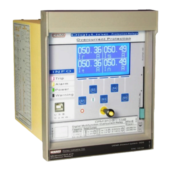
Summary of Contents for DEMA CPM 310 G
- Page 1 CPM 310 G Digital Overcurrent Protection Relay User & Application Manual vEN.2016.03...
- Page 2 - 2 -...
-
Page 3: Table Of Contents
Index About DEMA 1.1. General Information 1.2. Product Range 1.3. Contact Us p.10 Introduction p.11 2.1. General Specifications & Advantages p.12 2.2. Physical Introduction p.14 2.3. Protection and Reset Curves p.22 IEC Protection Curves p.23 2.3.1. IEC Thermal Overload Protection Curve p.25... - Page 4 >> Negative Sequence Overcurrent 2 Threshold Protection Menu p.74 5.6.8. )> Broken Conductor Protection Menu p.75 5.6.9. I< Phase Undercurrent Protection Menu p.76 5.6.10. > Thermal Overload Protection Menu p.77 5.6.11. Θ Auto-recloser Settings Menu p.80 5.6.12. 5.7. Main Menu p.83 Measurement Menu p.85...
- Page 5 Protection Settings p.149 6.4.4.1. Phase Protection Settings p.151 6.4.4.1.1. Earth Protection Settings p.152 6.4.4.1.2. Broken Conductor Protection Settings p.153 6.4.4.1.3. Negative Sequence Protection Settings p.154 6.4.4.1.4. Thermal (Overload) Protection Settings p.155 6.4.4.1.5. CT Settings p.156 6.4.4.2. System Settings p.157 6.4.4.3. Automatic Control Settings p.158 6.4.4.4.
-
Page 6: About Dema
ABOUT DEMA - 6 -... -
Page 7: General Information
2006 - CPM Series: The first draw out type DSP-based digital overcurrent protection relay with digital communication and LCD display features. DEMA Role San. ve Tic. A. S. invests more than 10% of its total revenue into R&D projects, which clearly demonstrates DEMA’s commitment into innovation. - Page 8 The molding workshop of DEMA is one of the most advanced facilities in its sector. The workshop works only for Prototyping, Or production molding construction for DEMA products. The molding workshop hosts Wire erosion machines, Through erosion machines, ...
-
Page 9: Product Range
Product Range 1. DSP-based Digital Protection Relays CPM 310 G Three phase + earth overcurrent protection relay with draw-out system. CPM 312 Three phase + earth overcurrent protection relay without draw-out system. T4CH 4 channel PT100 digital thermistor relay. 2. Annunciating System Components IT1-6 6-windows optical annunciator. -
Page 10: Contact Us
No.: 4, 34852, Maltepe, Istanbul, Turkey. Phone +90 (216) 352 77 34 +90 (216) 352 77 35 +90 (216) 442 17 95 E-mail dema@demarelay.com www.demarelay.com □ DEMA Role San. ve Tic. A. S. Plant at Istanbul, Turkey. - 10 -... -
Page 11: Introduction
INTRODUCTION - 11 -... -
Page 12: General Specifications & Advantages
A or (X/1) A conventional type current transformers. As a DSP based digital multi-function protection & control relay with 3 phase & earth overcurrent protection, DEMA CPM 310 G is tested to fulfill international standards requirements; and provides the users numerous assembly, commissioning and service advantages. - Page 13 General Specifications & Advantages Wide IEC, ANSI and custom delay curve support, DMT and IDMT delay curve support for all overcurrent protection functions, Annunciating functions and 7 optically coupled programmable inputs that eliminate the need to use external annunciators (e.g. to evaluate Buchholz, temperature and pressure signals). 8 outputs: Trip (SPDT) and watchdog (SPDT) plus 6 programmable outputs (2 SPDT + 4 SPST), ...
-
Page 14: Physical Introduction
Indicated with “Alarm” label on the front panel of CPM 310 G. LED light is in yellow color and runs according to configuration. Auxiliary Power LED Indicated with “Power” label on the front panel of CPM 310 G. LED is in green color and runs as long as the auxiliary supply is healthy. Internal Error LED Indicated with “Warning”... - Page 15 Internal Unit Lock As a subsystem of the patented DDS (DEMA Draw out System) technology, internal unit lock provides locking and drawing out of the internal unit with ease. Locking ensures safe electrical contacts. IP52 Reset Button Provides access to the LED and Alarm menus.
- Page 16 CPM 310 G: Rear View Case Earthing Screw Maximum operation safety is achieved via grounding of this earthing screw, which is the terminal point for the conductance continuity of the case and the internal unit construction. Terminal Blocks Made of inflammable materials, terminal blocks are designed to ensure safe connection and cabling.
- Page 17 CPM 310 G: Internal & External Units Circuit Diagram CPM 310 G Circuit diagram is fixed on the relay case. Users do not need to keep documents for basic cabling duties on the field thanks to this inerasable diagram. ...
- Page 18 CPM 310 G: Internal Unit – Front View Case Earthing Continuity Contact Provides the earthing continuity of the internal unit to the casing. The low-resistance spring contact is rated for prospected earth fault current. Current Transformers Transforms secondary current into useful signals to supply measurement and protection circuits with the information they need.
- Page 19 CPM 310 G: Internal Unit – Rear & Left Side View Internal Unit Terminal Sockets Sockets make the electrical connection by locking to the plugs when the internal unit is drawn into the case. All sockets are made of inflammable material.
- Page 20 Dip Switches CPM 310 G Digital Overcurrent Protection Relays can operate with X/1A or X/5A current transformers. The dip-switches shown on the image above enables the setting of the relay to work with X / 1 A or X / 5 A current transformers.
- Page 21 CPM 310 G: External Unit (Case) – Front View Mounting Screws for the Cover The cover is mounted onto the case via these screws. Screws are embedded and fixed on the case. Terminal Plugs Plugs make the electrical connection by locking to the sockets when the internal unit is drawn into the case.
-
Page 22: Protection And Reset Curves
DEMA CPM 310 G Overcurrent Protection Relays can employ and run IEC and IEEE / ANSI protection and reset curves, as well as a wide range of special curves that are mostly used when CPM 310 G units are used in the same selectivity scheme with older models of protection relays such as electromechanical relays. -
Page 23: Iec Protection Curves
IEC Protection Curves “IEC (International Electro-technical Commission) 60255-3, Electrical relays - Part 3: Single input energizing quantity measuring relays with dependent or independent time” standard describes the protection curves named as below. 1. IEC STI: IEC Short Time Inverse Curve. 2. - Page 24 The image below shows the trip delay curves for all IEC characteristics with TMS = 1. TMS can be set in the range (0.025 - 3.2) for any protection function. - 24 -...
-
Page 25: Iec Thermal Overload Protection Curve
θ trip parameters are considered, it is calculated that CPM 310 G relay can run 1,540,000 unique IEC Thermal Overload Protection curves; for its impossible to demonstrate all of the curves on a chart, sample curves are given on the below chart to express an overview of the characteristic. □... -
Page 26: Ansi / Ieee Protection Curves
ANSI / IEEE Protection Curves “IEEE (The Institute of Electrical and Electronics Engineers, Inc.) C37.112-2006: IEEE Standard Inverse-Time Characteristic Equations for Overcurrent Relays - Description” standard describes the protection curves named as below. 1. IEEE MI: IEEE Moderately Inverse Curve. 2. - Page 27 The image below shows the trip delay curves for all ANSI / IEEE characteristics with TMS = 1. TMS can be set in the range (0.025 - 3.2) for any protection function. - 27 -...
-
Page 28: Custom Protection Curves
Custom Protection Curves CPM 310 G Special Curves include inverse protection curves for electromechanical relays, constant time characteristic and reset curves. These curves are listed below. 1. SA Semic: Semiconductor Protection Curve. 2. SB DI: Definite Inverse Curve. 3. SC CO2: Short time Inverse Curve. - Page 29 The image below shows the custom trip delay curves with TMS = 1. TMS can be set in the range (0.025 - 3.2) for any protection function. - 29 -...
-
Page 30: Dmt: Definite Minimum Time Characteristic
DMT: Definite Minimum Time Characteristic DMT characteristic is used for obtaining constant trip and reset times. There are no parameters for the DMT characteristic other than the constant trip or reset time. Characteristic notation is as follows: e.g., t = DMT 0.25s. The image below shows the DMT characteristics for given current values. -
Page 31: Ridmt: Reset Inverse Definite Minimum Time Characteristics
CPM 310 G protects. The RIDMT parameters differ Table of CPM 310 G Protection and Reset Curves Parameters... -
Page 32: Packing & Labeling Information
PACKING & LABELING INFORMATION - 32 -... - Page 33 Packing & Labeling Information This section explains CPM 310 G packing information, package contents and introduces the device label. Packing Information Case Dimensions (17 x 20 x 24) (cm) [width x height x depth] Case Type Carton box with IP50 sealing.
-
Page 34: Operating Manual
OPERATING MANUAL - 34 -... -
Page 35: General Principles
General Principles Operating manual describes all operating procedures for CPM 310 G relays; starting from the mounting and cabling stages to maintenance and test procedure. Operation stages are shown on the below figure to visualize handling of the product free of problems. -
Page 36: Mounting
Mounting The following pages describe the mounting of CP 310 G case – for CPM 310 G relays are designed with draw-out system, the internal and external units can be handled independently during the mounting and cabling processes. PANEL CUT-OUT Flush mounting requires processing of the panel –... -
Page 37: Mounting The Case
MOUNTING THE CASE Mounting of the relay case on the prepared panel is done as described below. 1. Open the relay cover; preferably drive out the internal unit for easier mounting. If the internal unit is drawn out, take all precautions to prevent dusting and damaging of the unit. 2. -
Page 38: Cabling
Rear View and Terminals Legend CPM 310 G circuit diagram is located on the right side of the relay case when viewed from the front, and this diagram is given also in the following pages; on the other hand, the picture above will provide support for cabling practice by explaining the grouping logic of the terminals. - Page 39 Not used. Not used. Not used. CPM 310 G Terminal Explanations CAUTION! The “Notes” columns on the table suggests a sample application and is not normative. “DC(+)” notes, e.g., are given assuming that the circuit breaker, the power transformer and auxiliary devices are cabled in the way that their common terminals are supplied with DC(-).
- Page 40 The diagram below represents the inner circuit design of CPM 310. Sample cabling diagram is given on the following page. ↺ CPM 310 G Circuit Diagram - 40 -...
- Page 41 DEMA CPM 310 Sample cabling diagram is given below. The cabling color codes are given on the top right corner; according to the coding logic, DC (+) cables are in red, DC (-) are in black, AC (L or N)
-
Page 42: Cabling Material
CABLING MATERIAL Cabling material selection is important for all protection systems. The principles listed below are to be paid heed to build a robust system. Cabling with thin & multi-wire cables: Never make a connection without applying ferrules to wire ends! Use 18 mm wire end ferrules for all terminals no’s 1-32. -
Page 43: Setting
Setting After completing the mounting and cabling phases, relay settings can be done. Follow the procedure explained below. Each step has its own dedicated section to explain setting processes, as stated with page numbers. To ensure reliable operation, double check and note your settings. ↺ Dip-switch Settings, p.47 1 A / 5 A selection for phase and earth nominal current setting, (0.02-8) I or (0.1-40) I... -
Page 44: Example Setting And Calculation
It is required that the protection and alarming system of an oil-immersed type power transformer with characteristics 2,500 kV∙A, (34.5 / 0.4) kV, 50 Hz is erected, using DEMA CPM 310 G. Protection current transformers are selected as type 60 A / 5 A, 5 V·A 5P10 . - Page 45 5. Thermal protection of the power transformer, and phase and earth protections are to be done. Below calculations and settings are done for this purpose. Making of Iθ> Thermal Overload Protection Settings It is assumed that the thermal constant for the power transformer is Te = 20 minutes according to the information supplied by the manufacturer.
- Page 46 According to the calculation above, do the following settings: Main Screen » Set » I >> 6. All needed settings are done by now. Check all the settings and note them. CPM 310 G is ready for commissioning. □ Actual pick-up current values can be checked on page.
-
Page 47: Dip-Switch Settings
With respect to the principles hereby mentioned, the settings of CPM 310 G dip-switches must be done considering the instructions given in the following pages and with great care. - Page 48 1. In order to make the settings of the dip-switches, access to the internal unit must be provided. Drive out the internal unit. 2. Dip-switches are located in top right quadrant of the right side of the internal unit, when the unit is viewed from the front (see p.20).
-
Page 49: Example Dip-Switch Settings
WARNINGS DEMA CPM 310 G units are set to “ON – ON –ON – ON – ON” dip-switch settings by default. The default setting presumes that: the nominal current for phases and earth is 5 A the protection range for phases and earth is (0.1 - 40) I ... -
Page 50: Commissioning
Commission the System Check the Phase Rotation Use the measurement menus of CPM 310 G to make sure the phase rotation is correct - take corrective actions if necessary. - 50 -... -
Page 51: Operating
Operating NORMAL OPERATION After the successful commissioning of CPM 310 G, normal operation conditions are reached; this condition is kept as long as system components operate correctly and load current values are in tolerable limits. The purposes of electrical protection systems are; protecting the system components from abnormal conditions and minimizing system damage under those conditions, while providing maximum supply continuity and minimum black outs. -
Page 52: Testing & Maintenance & Reparation
CPM 310 G fuse. Analyze those possibilities and take the corrective actions; if the problem is caused by the CPM 310 G fuse, replace it by a new one with specifications Ø5 mm x 20 mm T1A (see p.19). Examine the possible causes of supply overcurrent that made the fuse burn. -
Page 53: Relay Menus Manual
RELAY MENUS MANUAL - 53 -... -
Page 54: Introduction
The upcoming screen when entered to a new menu is examined on a graphic showing the front view of CPM 310 G. If any menus that cannot be viewed on a single screen come across, another graphic on a fictional larger screen is added right behind it to demonstrate the full content of the menu. -
Page 55: The Menu Tree
The Menu Tree - 55 -... - Page 56 - 56 -...
- Page 57 - 57 -...
- Page 58 - 58 -...
- Page 59 - 59 -...
- Page 60 - 60 -...
- Page 61 - 61 -...
-
Page 62: Reset Menu
Reset Menu (Reset Cycle) Reset Reset Menu is reached by pressing the button Reset while at any menu. The location of the button is pointed in the middle picture. The menu displays any active alarms generated by active protection and supervision functions, and lets the user read and delete Active Initial... - Page 63 Note that the external button on the CPM 310 G cover provides IP52 protection and eliminates the need of Reset cover removal to access the button.
-
Page 64: Circuit Breaker Monitoring And Control Menu
Circuit Breaker Monitoring and Control Menu Circuit Breaker Monitoring and Control Menu is represented as “Breaker” on the main screen and is accessed by S1 button, as shown on the picture to the left. Circuit Breaker Monitoring and Control Menu displays the position of the circuit breaker as “OFF”... -
Page 65: Settings Group Selection Menu
“G1” abbreviation shows that CPM 310 G is operating under no.1 group of settings and “G2” abbreviation shows that CPM 310 G is operating under no.2 group of settings. Settings Group Selection Menu provides easy and rapid transition possibility between groups of settings. -
Page 66: Protection And Control Settings Menu
Protection and Control Settings Menu Protection and Control Settings Menu is reached from the “Set” command from the main screen by pressing “S4” button, as shown on the picture to the left. Menu content is shown on the picture below. As shown, the menu provides access to the 12 protection and control functions;... -
Page 67: I> Phase Overcurrent
0.04 seconds. DEMA CPM 310 G has DMT (Definite Minimum Time) and IDMT (Inverse Definite Minimum Protection and Reset Curves Time) options as reset characteristics. -
Page 68: I>> Phase Overcurrent
0.04 seconds. DEMA CPM 310 G has DMT (Definite Minimum Time) and IDMT (Inverse Definite Minimum Protection and Reset Curves Time) options as reset characteristics. -
Page 69: I>>> Phase Overcurrent 3
0.04 seconds. DEMA CPM 310 G has DMT (Definite Minimum Time) and IDMT (Inverse Definite Minimum Protection and Reset Curves Time) options as reset characteristics. -
Page 70: Earth Overcurrent 1
0.04 seconds. DEMA CPM 310 G has DMT (Definite Minimum Time) and IDMT (Inverse Definite Minimum Protection and Reset Curves Time) options as reset characteristics. -
Page 71: Earth Overcurrent 2
0.04 seconds. DEMA CPM 310 G has DMT (Definite Minimum Time) and IDMT (Inverse Definite Minimum Protection and Reset Curves Time) options as reset characteristics. -
Page 72: Earth Overcurrent 3
0.04 seconds. DEMA CPM 310 G has DMT (Definite Minimum Time) and IDMT (Inverse Definite Minimum Protection and Reset Curves Time) options as reset characteristics. - Page 73 0.04 seconds. DEMA CPM 310 G has DMT (Definite Minimum Time) and IDMT (Inverse Definite Minimum Time) options as reset characteristics. Please see the...
- Page 74 0.04 seconds. DEMA CPM 310 G has DMT (Definite Minimum Time) and IDMT (Inverse Definite Minimum Time) options as reset characteristics. Please see the...
- Page 75 )> Broken Conductor Protection Menu Broken Conductor Protection is symbolized as )> or I > in the IEC Standards, where I describes the positive sequence current and I describes the negative sequence current. )> protection is utilized to intervene the primary circuit in cases where one or two primary phase conductors are broken (I = 0 A) but there is no fault current, or one or two secondary wirings are open...
-
Page 76: I< Phase Undercurrent Protection Menu
I< Phase Undercurrent Protection Menu Phase Undercurrent Protection is symbolized as I< in IEC Standards, and coded as 37 in IEEE/ANSI Standards. I< symbol indicates that the protection function monitors the phase current and intervenes when current values below the 1 threshold are detected. - Page 77 > Thermal Overload Protection Menu Θ Thermal Overload Protection is symbolized as I > in Θ IEC Standards, and coded as 49 in IEEE/ANSI Standards. > symbol indicates that the protection function Θ measures the phase RMS current and behaves according to the thermal overload protection formula.
- Page 78 Trip Θ allowed before tripping. is set to typical %100 by default, on the other hand, CPM 310 G provides the user the flexibility to set this value between %50 and %200 to fulfill the requirements of exceptional applications. When the calculated heating percentage Trip Θ...
- Page 79 Thermal Θ Alarm Θ When measurement reaches threshold, the user is notified via the static alarm LED on the frontal face of CPM 310 G, while the alarming Alarm Menu situation is declared on the . The use of Alarm Menus will be examined thoroughly on the dedicated section in the following pages.
-
Page 80: Auto-Recloser Settings Menu
The CPM 310 G auto-recloser function has the following characteristics: Auto-reclose shots up to 4 cycles, Main Screen » Set » ARCL ... - Page 81 (0.20-600.0) s. As described before, DEMA CPM 310 G relays are capable of handling independent procedures of auto- reclosing when phase fault, earth faults or auxiliary timer triggers operate.
- Page 82 The tripping settings (shown within the red borders on the picture in the middle) determine the tripping behavior of the circuit breaker within the auto-reclosing cycles, if a function (e.g. tI>) generates a trip decision. The line under the title describes cycle numbers and the line at the bottom comprises the settings.
-
Page 83: Main Menu
Main Menu DEMA CPM 310 G Main Menu is accessed via the MENU button (S5) on the main screen, as pictured on the left. The middle and bottom pictures show the whole menu content. Explanations on the sub-menus seen on the picture at the bottom will be studied in the following sections. - Page 84 Function Test Menu Function Test Menu enables the testing function that conducts the final tests of the settings, functionality and cabling done before commissioning CPM 310 G. The function basically generates virtual current around 40 I to check and supervise the settings, functionality and cabling.
-
Page 85: Measurement Menu
Measurements Menu Measurements Menu is where the momentary, cumulative and statistical values are accessed which CPM 310 G watches continuously. As seen on the pictures to the right, the menu comprises RMS Current Measurements Menu, Max. RMS Current Measurements Menu, ... -
Page 86: Rms Current And Frequency Measurements Menu
“XX.XX”, as on the top picture. WARNING! Frequency To ensure the correct operation and measurements of DEMA CPM 310 G relays, the System Settings parameter at the Menu has to be set correctly! Inappropriate settings may cause in... -
Page 87: Max Rms Current Measurements Menu
Max RMS Current Measurements Menu Max. RMS Measurements Menu displays the measured maximum R, S, T and N line RMS current values since the last resetting. Max RMS Current Measurements menu; Makes it possible to check the inrush current of the protected system and fine-tune the protection functions, ... -
Page 88: Fundamental Harmonics Measurements Menu
Harmonics displayed as 40 I or 40 I For the fact that DEMA CPM 310 G evaluates the primary current values by utilizing the information acquired from the secondary signals and the Settings... -
Page 89: Positive And Negative Sequence Current Measurements Menu
Positive & Negative Sequence (P/N) Current Measurements Menu Positive and Negative Sequence Current Measurements Menu screen is shown on the left picture. The menu monitors the following measurements. I1 (Positive Sequence Measurement) Positive sequence component of the phase current values is formulated as follows. ×... -
Page 90: Thermal Θ Measurements Menu
Thermal Θ Measurements Menu Thermal Θ Measurements Menu displays the heating percentage of the system being watched in percentages. Thermal Θ is evaluated according to the IEC formulations; the actual formula is given below. �� �� − %�� �� �� × �� ��... -
Page 91: Input & Output Status Monitoring Menu
Note that the watchdog relay has a unique activation behavior. Unlike the other outputs, the watchdog relay closes by default when CPM 310 G is in service. This results from the nature of the relay - the watchdog relay opens contacts only when there is an auxiliary supply shortage or internal error. -
Page 92: Circuit Breaker Measurements
Note that the measurement is effective only when the closing command is carried out over the relay. Open Numerator Trip operations conducted via CPM 310 G is counted and displayed on this field. ∑A (R, S, T) As shown on the image above, These measurements are the summation of the RMS the ∑A and ∑A... -
Page 93: Auto-Recloser (Arcl) Measurements Menu
ARCL when an auto-recloser session is completed. The example below is given presuming that the CPM 310 G unit is configured to make two auto-reclose shots when the CB is tripped by I>> function. 1. When the CB is tripped by the I>> function, the auto-recloser would conduct a reclose shot. -
Page 94: Led Status Menu
LED Status Menu LED Status Menu displays the status of all programmable virtual LEDs, which are programmed LED Settings Menu Automatic through the under the Control Functions Menu The sample LED status picture on the left shows that there are 4 active programmable LEDs (L5 – L8), that tell the tI>, tI>>, tI >... -
Page 95: Communication Settings Menu
38,400 bauds. Relay Address When more than one units of CPM 310 G are to be watched and/or controlled remotely, relay addressing becomes essential. DEMA CPM 310 G Relays allow addressing in integers from 1 to 255. The default address is “001”. □... -
Page 96: Event Records Menu
Event Records Menu Event Records Menu contains the records of CPM 310 G actions that are related with settings changes, detected disturbances, detected faults, input & output status changes an alarms. Up to 151 records can be viewed on the menu. -
Page 97: System Settings Menu
The explanations of the settings and options available on the menu are given below. Time Time setting is accessed and used by CPM 310 G for Main Screen » Menu » time stamping in recording functions such as System Settings waveform, event and fault recording. - Page 98 WARNING! If a password is lost or forgotten, there is no way to recover the password via CPM 310 G! In such a case, the password reset process can only be done via PC program. Remember that when passwords other than “0000”...
- Page 99 “Active”, password validation will be required to access the CB Control Menu. Default setting is “Passive”. Load Default Settings If by any reason, the CPM 310 G unit settings are to be Load Default Settings reset to the default settings, command should be utilized.
-
Page 100: Current Transformer Settings Menu
This informative field is where the secondary phase nominal current is set in amperes. The options are 1 A and 5 A. While DEMA CPM 310 G handles and evaluates the secondary signals not according to this field but the dip-switch settings, however, selecting the wrong option on this field may misinform Dip-Switch Settings the users. - Page 101 WARNING! Setting current transformers characteristics on the Current Transformers Menu does not provide the correct operation of CPM 310 G by itself; but also, the dip-switch settings must also be done! Incomplete and inappropriate settings on the menus and dip-switches...
-
Page 102: Automatic Control Settings Menu
Automatic Control Settings Menu Automatic Control Settings Menu has the entire settings options other than protection and measurement controls. The controls in this menu are listed below; Cold Load Pickup Settings, Output Relay Settings, Trip Settings, Input Settings, ... -
Page 103: Cold Load Pickup Settings Menu
Cold Load Pickup Settings Menu Cold Load Pickup (CLP) feature of CPM 310 G provides the option to pull up delay times of desired protection functions to enable easy pickup of machines and systems with high pickup / inrush current without protection relay intervention. - Page 104 Covered Functions (Active / Passive) The entire control lines other than those described in the previous page are used for declaring CPM 310 G which protection functions are to be covered by the CLP functionality. By setting each of the listed functions...
-
Page 105: Output Relay Settings Menu
The configuration of the 6 programmable outputs of Output Relay Settings Menu CPM 310 G is done via the As shown on the picture, the first line of the menu displays the output addresses (1, 2, 3, 4, 5, 6) and the following lines display the assignable functions (e.g. -
Page 106: Trip Settings Menu
Automatic Control Settings » a specified limit, Trip Settings • A function test of CPM 310 G may be needed to be conducted online – in this case, setting all parameters in Trip Settings Menu will do the trick. As seen on the pictures to the left, all functions that normally lead to the tripping of the CB can be controlled from the menu. -
Page 107: Input Settings Menu
Input Settings Menu Input Settings Menu is a control menu where the existing 7 programmable inputs of DEMA CPM 310 G relays are programmed and decided how to behave. The picture at the top displays the welcome screen and the picture beneath shows the rest of the contents of... -
Page 108: Blocking Logic Selectivity Settings Menu
Blocking Logic Selectivity Settings Menu Blocking Logic Selectivity Settings Menu (Displayed Blocking Settings briefly as on the relay menus) is a control menu that enables the users to utilize the Blocking Logic Selectivity scheme on a number of relays that are protecting the same circuit, and are installed Blocking Logic Selectivity back-to-back. - Page 109 Blocking Selectivity Settings When the menu is entered (top picture), the user is asked to select the settings group. Once the selection is made by the button ), the submenu shown on the middle and bottom pictures appear. Note that the title of the submenu includes the settings group name, e.g.
- Page 110 Obtaining selectivity using the Blocking Logic Selectivity function (Application Diagram 8, p.201). Settings Made: R1: CB Failure, R4: I>>, I>>>, I >>, I >>>, I : Blocking Sel.1. - 110 -...
- Page 111 . The default value of 0.02 I , which is limited by the lowest current reading capability of CPM 310 G, is not recommended to be changed for normal application. Special cases need further study which will not be discussed here. ↺...
- Page 112 tCBF (CB Pole Failure Delay Time) tCBF is the delay time counter limit value before alarming, which is triggered at the instant that the trip signal is generated, and terminated if the primary circuit current drops below the threshold current. The setting zone for the counter is (0.01 – 10) s in 10 ms steps. The default value for tCBF is 1.0 s, however, tCBF value is not recommended to exceed 100 ms if the function is to be used in blocking logic selectivity schemes.
-
Page 113: Auxiliary Timer Settings Menu
Auxiliary Timer Settings Menu DEMA CPM 310 G Overcurrent Protection Relays are equipped with 2 independent auxiliary timers. These timers are set to trip the circuit breaker by default, but can be utilized for wide range of applications. Auxiliary timers can be triggered via inputs that are... -
Page 114: Delaying Logic Selectivity Settings Menu
On the submenu, it is decided whether the protection function tripping times are to be translated or not when CPM 310 G unit receives a delaying signal, as described recently. The sample picture on the bottom of the previous page shows the default settings, which will not allow any delaying actions to be trigger by inputs. - Page 115 The CPM 310 G auto-recloser function has the following Main Screen » Set » ARCL characteristics: Auto-reclose shots up to 4 cycles, ...
- Page 116 (0.20-600.0) s. As described before, DEMA CPM 310 G relays are capable of handling independent procedures of auto- reclosing when phase fault, earth faults or auxiliary timer triggers operate.
- Page 117 The tripping settings (shown within the red borders on the picture in the middle) determine the tripping behavior of the circuit breaker within the auto-reclosing cycles, if a function (e.g. tI>) generates a trip decision. The line under the title describes cycle numbers and the line at the bottom comprises the settings.
-
Page 118: Cb Supervision Settings Menu
CB Supervision Settings Menu CB Supervision Settings Menu monitors and configures the following 9 functions that are effective on the CB. Opening Time Supervision This function measures and supervises the time interval between the generation of tripping impulse and the disappearance of 52a signal from the CB. - Page 119 6. CB Numerator Supervision This function counts and supervises the tripping operation of the CB triggered by the tripping Numerator Limit relay of CPM 310 G; if the count exceeds the set value , the function triggers CB Alarm CB Numerator Alarm...
- Page 120 9. Trip Circuit Supervision CPM 310 G relays are capable of checking the electrical continuity of the trip circuit (the circuit Trip Relay that connects the ) of CPM 310 G and the release coil of the CB); by utilizing TRIP the Trip Circuit Supervision function.
- Page 121 LEDs are configured. Note that the programmable LEDs are viewed on the LED Menu, which is accessed simply by pressing the Reset button once while on any menu of CPM 310 G. Main Screen » Menu » Automatic Control Settings »...
- Page 122 The setting procedure is described below. 1. Select the programmable LED to be set on the LED Settings Menu by navigating on the menu and press S5 (ENT) button to proceed to the sub-menu, 2. The sub-menu contains the list of functions that can activate the LED that the sub-menu belongs to.
- Page 123 Latch Settings Menu Latch Settings Menu contains the controls that determine the latching behavior of functions and programmable outputs. By default, the protection and auxiliary timer functions do not latch the Trip Relay or the other relays that they are appointed to; similarly, programmable outputs do not latch when activated by any functions.
- Page 124 Outputs that can be latched are listed below: 1. TRIP CB Trip Output; via settings of the 13 protection functions above. 2. RL1 Programmable Output 1. 3. RL2 Programmable Output 2. 4. RL3 Programmable Output 3. 5. RL4 Programmable Output 4. 6.
-
Page 125: Alarm Settings Menu
Alarm Settings Menu Alarm Settings Menu controls the behavior of the Alarm Menu, which is accessed simply by pressing the Reset button twice regardless of what CPM 310 G menu is being displayed at that time. Alarm Resetting control in the menu lets the user... -
Page 126: Function Test Menu
Function Test Menu Function Test Menu is a test triggering menu, via which a test is launched to check the functionality of the CPM 310 G unit and the trip circuit. When the Function Test Menu is accessed, the user is asked to enter the password. -
Page 127: Fault Records Menu
Fault Records Menu Fault Records Menu displays fault records that are filtered and derived from the event records. The filtering method is based on the elimination of the events not resulting with tripping. The display characteristics are same with that of event records. The design of the menu focuses on rapid access to the first and brief information about the faults when occurred. -
Page 128: Digiconnect Pc Program Manual
DIGICONNECT PC PROGRAM MANUAL - 128 -... -
Page 129: Operating System & Hardware Requirements
Operating System & Hardware Requirements DEMA DigiConnect Software operation system and hardware requirements to provide a successful setup and runtime are listed below. DigiConnect – Operating System Compatibility Microsoft Windows 98SE Microsoft Windows 2000 Microsoft Windows XP 32-bit / 64-bit ... -
Page 130: Program Setup
Program Setup DEMA DigiConnect program setup may be launched by the following ways. 1. For operating systems where CD-ROM or DVD-ROM is set as to enable auto-start, the setup process will launch automatically when the DigiConnect CD is inserted into the optical disc drive. - Page 131 After pressing OK button to continue with the setup, the menu shown by the Setup Dialogue 3 picture on the left pops up. The menu contains the following text: Begin the installation by clicking the button below. Click this button to install DigiConnect vX.XX software to the specified destination directory.
- Page 132 Existing Groups: Dema The program group name may be left as the default title Dema, or be changed to another descriptive title the user decides suitable. Once the group name is decided, press the Continue button to install the program. The Cancel button on...
-
Page 133: Program Startup
After the setup of the DigiConnect program is completed, it can be launched utilizing one of the methods described below. The program can be launched; via the Start Menu by accessing: Start » Programs » Dema » DigiConnect. by double clicking the DigiConnect shortcut automatically Startup Dialogue 1 created by setup. - Page 134 Ports. On the picture in the next page, the USB connection port of PC to CPM 310 G has been located. Notice that, according to the picture, the communication port address is COM4. Once the port address is obtained as described, set the Communication Port parameter to the obtained address.
- Page 135 CPM 310 G via a PC is intended, setting the baud rate to 38,400 will be most favorable. Remark When direct communication to CPM 310 G via a PC is Device Manager Dialogue intended, the communications settings of CPM 310 G must be analogous to the settings shown on Startup Dialogue 4.
-
Page 136: Software Introduction And Guide
Software Introduction and Guide Sample Screenshot DigiConnect software is developed and released for Microsoft Windows based systems, and utilizes standard Windows forms. General Windows knowledge is sufficient to work comfortably with DigiConnect software. On the following pages of DigiConnect PC Program Manual, the menu being explored is shown with a screenshot, similar to the sample above. -
Page 137: Welcome Screen
Welcome Screen On the upper side of Welcome Screen, shortcuts to the menus listed below are located. It is also possible to reach the same menus by exploring the tabs below the shortcuts. 1. Measurements shortcut leads to the measurement menus; 2. -
Page 138: Measurements
Measurements » Analog Values » RMS Current 1. Phase and earth current RMS momentary values are monitored in this region. Values are given in amperes. 2. Thermal Θ (heating percentage) values are monitored in this region. The thermal heating percentage shown here is the cumulative evaluation made by using the set parameters and RMS current measurements. -
Page 139: Fundamental Harmonics
Measurements » Analog Values » Fundamental Harmonics 1. Fundamental Harmonics window displays the fundamental harmonic component (f = 50 Hz / 60 Hz) of the phase and earth current filtered of higher order harmonics. 2. Frequency window displays the actual network power frequency measured on the secondary circuit. □ - 139 -... -
Page 140: P/N Sequences
Measurements » Analog Values » P/N Sequences 1. P/N (Positive / Negative) Sequences window displays the positive and negative sequence components of the measured fundamental component of the secondary current; as absolute values in amperes and as proportion in percentage. □ - 140 -... -
Page 141: Max. Rms Current
Measurements » Analog Values » Max. RMS Current 1. Max RMS Current window displays the maximum value of the phase & earth RMS current since the last reset, in amperes or kiloamperes. Max RMS current values can be reset for each phase and earth individually by using the Reset buttons next to each of them. - Page 142 Measurements » Breaker Measurements 1. CB Measurements window monitors and records all of the circuit breaker activity. The window displays: Durations of the last closing and tripping operations, in seconds; Total tripping numerator; Cumulative total tripping current for each of R, S and T phases, in amperes (A); ...
-
Page 143: Arcl Measurements
Measurements » ARCL Measurements 1. ARCL (Auto-recloser) Measurements window displays the cumulative and individual values of reclosing cycles, and the total number of auto-recloser blockings. As seen on the picture above; the left column gives the explanations of the monitors to their right (e.g. Total cycle), the middle column comprises of the 5-digit monitors, and the column at the far right contains the buttons to reset each of the monitors. -
Page 144: Remote Control
Measurements » Remote Control Remote Control tab comprises controls that enable the user to take remote control the CB and the programmable outputs. 1. CB (Circuit Breaker) window is used for controlling the circuit breaker via the Open and Close buttons. 2. -
Page 145: Alarms
Delete Selected button does the same job for a selected record. NOTE When DigiConnect program is launched, no records exist or displayed at the Alarms window. To download and display alarms from CPM 310 G, use the Refresh (1) button. □ - 145 -... -
Page 146: Event Records
All details of the event records printed will be available on the document. NOTE When DigiConnect program is launched, no records exist or displayed at the Event Records window. To download and display even records from CPM 310 G, use the Refresh (1) button. □ - 146 -... -
Page 147: Trip Records
» Trip Records Alarms / Event Records Trip Records window acquires data from the CPM 310 G memory to display fault records. Trip records are filtered and derived from the event records. The filtering method is based on the elimination of the events not resulting with tripping. The acquisition, display and evaluation principles are same with those of event records. - Page 148 Settings 1. Settings tab is displayed on the above picture. Via this tab, it is possible to access; Protection Settings window, b. CT Settings window, System Settings window, d. Automatic Control Settings window, and Communication Settings window. The introductions to the mentioned windows are given in the following pages. □ - 148 -...
-
Page 149: Protection Settings
Settings » Protection Settings 1. When Protection Settings button is clicked under the Settings tab, the window titled Protection Settings Group Selection is displayed. On this window, the group that the settings will be in effect must be selected to proceed further. The Back button below the settings group buttons leads back to the main menu of settings. -
Page 150: Settings Menu
Settings » Protection Settings » Protection Settings Group 1/2 1. Once the protection settings group selection is done, the protection settings menu is reached. This menu comprises the setting menus of following functions: Phase Protection Settings, b. Earth Protection Settings, Broken Conductor Protection Settings, d. -
Page 151: Phase Protection Settings
B. Save to Buffer button sends the parameter changes to the DigiConnect buffer. When changes are to be applied to CPM 310 G unit, Save to Device button must be utilized, which is located under the Buffer tab. 1. Phase overcurrent 1 threshold protection (I>) (ANSI 50/51) parameters and settings area,... -
Page 152: Earth Protection Settings
B. Save to Buffer button sends the parameter changes to the DigiConnect buffer. When changes are to be applied to CPM 310 G unit, Save to Device button must be utilized, which is located under the Buffer tab. 1. Earth overcurrent 1 threshold protection (I >) (ANSI 50N/51N) parameters and settings area,... -
Page 153: Broken Conductor Protection Settings
B. Save to Buffer button sends the parameter changes to the DigiConnect buffer. When changes are to be applied to CPM 310 G unit, Save to Device button must be utilized, which is located under the Buffer tab. 1. Broken conductor protection parameters and settings area. -
Page 154: Negative Sequence Protection Settings
B. Save to Buffer button sends the parameter changes to the DigiConnect buffer. When changes are to be applied to CPM 310 G unit, Save to Device button must be utilized, which is located under the Buffer tab. 1. Negative sequence overcurrent 1 threshold protection (I >) (ANSI 46) parameters and settings area,... -
Page 155: Thermal Protection Settings
B. Save to Buffer button sends the parameter changes to the DigiConnect buffer. When changes are to be applied to CPM 310 G unit, Save to Device button must be utilized, which is located under the Buffer tab. 1. Thermal overload protection (I >) (ANSI 49) parameters and settings area. -
Page 156: Ct Settings
B. Save to Buffer button sends the parameter changes to the DigiConnect buffer. When changes are to be applied to CPM 310 G unit, Save to Device button must be utilized, which is located under the Buffer tab. 1. CT Settings window embeds the settings options for primary and secondary nominal current for phases and earth. -
Page 157: System Settings
B. Save to Buffer button sends the parameter changes to the DigiConnect buffer. When changes are to be applied to CPM 310 G unit, Save to Device button must be utilized, which is located under the Buffer tab. 1. CPM 310 G basic settings are made via the System Settings window under the Settings tab. The menu monitors the system firmware version;... -
Page 158: Automatic Control Settings
Settings » Automatic Control Settings 1. Automatic Control Settings window layout enables full scale access to the automatic control functions of CPM 310 G via DigiConnect program. Menus of automatic control functions that CPM 310 G can utilize are listed below. -
Page 159: Input Settings
For the case shown above, CPM 310 G does evaluate the input to be passive as long as there are no signals at the inputs. - Page 160 B. Save to Buffer button sends the parameter changes to the DigiConnect buffer. When changes are to be applied to CPM 310 G unit, Save to Device button must be utilized, which is located under the Buffer tab. 1. Timer Settings window houses the existing value indication and parameter editing fields for the 2 independent auxiliary timers embedded within DEMA CPM 310 G.
-
Page 161: Output Relay Settings
B. Save to Buffer button sends the parameter changes to the DigiConnect buffer. When changes are to be applied to CPM 310 G unit, Save to Device button must be utilized, which is located under the Buffer tab. 1. On the very left of these columns; thresholds (e.g. I> and I >), time delay protection functions (e.g. -
Page 162: Trip Settings
B. Save to Buffer button sends the parameter changes to the DigiConnect buffer. When changes are to be applied to CPM 310 G unit, Save to Device button must be utilized, which is located under the Buffer tab. 1. Alternatives in the Trip Settings window provide the user to choose whether the defined protection functions can trigger a trip process or not. -
Page 163: Blocking (Logic) Selectivity Settings
B. Save to Buffer button sends the parameter changes to the DigiConnect buffer. When changes are to be applied to CPM 310 G unit, Save to Device button must be utilized, which is located under the Buffer tab. 1. Blocking (Logic) Selectivity Settings menu comprises settings of functions to involve in blocking logic selectivity activities. -
Page 164: Cb Failure Settings
B. Save to Buffer button sends the parameter changes to the DigiConnect buffer. When changes are to be applied to CPM 310 G unit, Save to Device button must be utilized, which is located under the Buffer tab. 1. CB Failure Settings window comprises the control for having the CB protection function into or out of service, as well as parameter setting fields. -
Page 165: Delaying (Logic) Selectivity Settings
B. Save to Buffer button sends the parameter changes to the DigiConnect buffer. When changes are to be applied to CPM 310 G unit, Save to Device button must be utilized, which is located under the Buffer tab. 1. Delay Selectivity Settings menu includes settings of functions to involve in delaying logic selectivity actions. -
Page 166: Auto Recloser Settings
Settings » Automatic Control Settings » Auto-recloser Settings Auto-reclose Settings Group Selection menu is reached when Auto-reclose Settings button is hit under the Automatic Control Settings window. 1. Auto-reclose settings are done for two independent settings groups, as in the case for protection settings. To access to the Auto-reclose Settings menu, a settings group must be selected first at the screen shown above. - Page 167 Save to Buffer button sends the parameter changes to the DigiConnect buffer. When changes are to be applied to CPM 310 G unit, Save to Device button must be utilized, which is located under the Buffer tab. This area comprises functionality and characteristics monitoring and modifying fields for the AR function.
-
Page 168: Cold Load Pickup Settings
B. Save to Buffer button sends the parameter changes to the DigiConnect buffer. When changes are to be applied to CPM 310 G unit, Save to Device button must be utilized, which is located under the Buffer tab. 1. Cold Load Pickup Settings window allows the users to set the functionality and parameter variables via the DigiConnect program. -
Page 169: Cb Supervision Settings
B. Save to Buffer button sends the parameter changes to the DigiConnect buffer. When changes are to be applied to CPM 310 G unit, Save to Device button must be utilized, which is located under the Buffer tab. 1. CB Supervision window allows the users to have the various types of circuit breaker supervision functions into or out of service and set the needed parameters for them. -
Page 170: Programmable) Led Settings
B. Save to Buffer button sends the parameter changes to the DigiConnect buffer. When changes are to be applied to CPM 310 G unit, Save to Device button must be utilized, which is located under the Buffer tab. LED setting principles have been examined thoroughly back at the dedicated section in the Relay Menus Manual. -
Page 171: Latch Settings
If the trip relay or any programmable relays are desired to be latched, the appropriate functions must be set to Active. Note that, if any latch settings are done, latching of the related relays will be active until CPM 310 G is reset. □... -
Page 172: Alarm Settings
B. Save to Buffer button sends the parameter changes to the DigiConnect buffer. When changes are to be applied to CPM 310 G unit, Save to Device button must be utilized, which is located under the Buffer tab. 1. Alarm Settings window provides monitoring of the active settings and editing the following parameters: ... -
Page 173: Communication Settings
If communication settings are changed via DigiConnect program, the communication between CPM 310 G and PC will be reset and lost. Restart of the program and reconnection to the CPM 310 G unit with the updated communication settings will be needed to carry on working! □... -
Page 174: Buffer Menu
1. Changed Settings window displays the settings changes that are made on the DigiConnect menus and sent to the buffer, but not loaded to CPM 310 G yet. As seen on the picture above, changes or main titles that contain changes are highlighted in red, until they are applied to CPM 310 G utilizing the Send to Device control. - Page 175 Buffer Menu The picture above displays the pop-up window when the Create Password Key button is clicked. When the button is hit, DigiConnect automatically creates a password recovery file named pss.pass and save it in the DigiConnect setup directory. Buffer Menu The picture above shows that a setting change (at Phase Protection Settings of Protection Settings Group 1) is done on the PC program, but not has been sent to the device yet.
- Page 176 The picture above describes a case that a change on protection settings is made and sent to the buffer. Clicking Send to Relay button at this stage will load the changes to CPM 310 G unit, removing the highlights on the Changed Settings window and the Send to Relay button.
- Page 177 Create Template File button saves the changes made since the last settings update from DigiConnect program to create a file that can manipulate any CPM 310 G units with the same changes in settings. Like the Send to Relay button, the Create Template File button remains in passive condition and in dim color if there is nothing to be saved at the buffer.
- Page 178 Buffer Menu When the actions on the Template Information window are done, OK button is pressed to advance to the next step. The next window is a standard Windows Save As dialog box, asking for the file saving name and location. Once the file name and location is decided and OK button is clicked, the template file creation process is completed (see the picture below).
- Page 179 Another control button, named Load Template File, enables the user to load existing template files to the buffer. Once this is done, the setting changing orders within the file can be sent and applied to CPM 310 G by hitting the Send to Relay button.
- Page 180 Waveform records provide network administrators important information where supply problems or protection errors occur frequently, protection settings convenience needs to be checked or fault characteristics are to be evaluated in detail. DEMA CPM 310 G presents the users this powerful tool with the following characteristics.
- Page 181 : minute : second : millisecond, day / month / year format. 2. Clear All Records button deletes all the records existing on CPM 310 G memory. Before taking this action, it must be understood that this process is irreversible and all records that are not archived will be permanently lost.
- Page 182 Once one of the existing records is selected and Show command is given, DigiConnect downloads the requested data from CPM 310 G to its temporary memory field. Then the downloaded data is processed to form the user interface Disturbance Records on Relay, where waveforms and viewing commands are displayed. On the top left side of this new pane File and View menus are located.
- Page 183 Disturbance Records The File menu on the top left side of the pane embeds the Save and Close commands. Save command launches the archiving process of the loaded waveform record (shown below), while Close command terminates the Disturbance Records on Relay. ↺ - 183 -...
- Page 184 Disturbance Records The View menu on the top left side of the pane embeds two sub-menus: 1. Toolbars, 2. Graphics. Toolbars submenu contains the Time Bars command, which activates two time sticks for each current-time graphics. Time bars allow the user to measure time between any two desired points (shown below). ↺ - 184 -...
- Page 185 Disturbance Records Time bars behave independent on all current-time graphics. The bars are titled as “1” and “2”, and are positioned freely by clicking on the title and then clicking on an alternative point on the graphic. When the bars are moved, the time monitors on the right side of the screen display: ...
- Page 186 Disturbance Records When right-clicked on any point of one of the waveform graphics, a menu with 5 commands appears, as seen on the picture above. The commands and their duties are explained below: Zoom In Activates the zoom in tool. When the tool is activated, each right click on the graphic will zoom in to display a narrower range of the waveform.
- Page 187 Disturbance Records On the picture above, it is observed that phase R waveform graphics is zoomed in to display approximately 3 cycles of the current wave. Note that the 1ms time lines are activated via Layout » Graphics » Time Lines command.
- Page 188 Disturbance Records » Get From File The second option to view the waveform records is to download and display waveform records from the local PC drives, utilizing the Get From File button. The picture above displays a sample screen that Get From File button leads to.
-
Page 189: Application Diagrams
APPLICATION DIAGRAMS - 189 -... -
Page 190: On The Use Of Application Diagrams
It is required that, the protection and alarming system of an oil-immersed type power transformer with characteristics 2,500 kV·A, 34.5 kV / 0.4 kV, 50 Hz is to be done, using DEMA CPM 310 G. Protection current transformers are selected as type 5 V·A, 5P20, (60/5)A . - Page 191 Sample Power Transformer Protection Application Diagram - 191 -...
- Page 192 Application Symbol Description Diagram No. I> Phase Overcurrent 1st Threshold Protection I>> Phase Overcurrent 2nd Threshold Protection I>>> Phase Overcurrent 3rd Threshold Protection > Earth Overcurrent 1st Threshold Protection >> Earth Overcurrent 2nd Threshold Protection >>> Earth Overcurrent 3rd Threshold Protection )>...
-
Page 193: Fundamental Cabling Diagram
FUNDAMENTAL CABLING DIAGRAM - 193 -... -
Page 194: Application Diagram No. 1
APPLICATION DIAGRAM NO. 1 - 194 -... -
Page 195: Application Diagram No. 2
APPLICATION DIAGRAM NO. 2 - 195 -... -
Page 196: Application Diagram No. 3
APPLICATION DIAGRAM NO. 3 Function Function Activation Address Settings Input MENU » Automatic Control Settings » Input Settings » 1-7.Input » 52a Auto-recloser Add » ARCL Output MENU » Automatic Control Settings » Output Settings » 1-6.Output » CB Close CB Trip Time Input MENU »... -
Page 197: Application Diagram No. 4
APPLICATION DIAGRAM NO. 4 Function Function Activation Address Settings Input Reset Latch Automatic MENU » Automatic Control Settings » Input Settings » 1-7.Input » Reset Latch Input tAux1 Automatic MENU » Automatic Control Settings » Input Settings » 1-7.Input » Start tAux1 Input tAux2 Automatic... -
Page 198: Application Diagram No. 5
APPLICATION DIAGRAM NO. 5 Function Function Activation Address Settings Input Buchholz Alarm Automatic MENU » Automatic Control Settings » Input Settings » 1-7.Input » Buchholz Alarm Input Buchholz Trip Automatic MENU » Automatic Control Settings » Input Settings » 1-7.Input » Buchholz Trip Input Thermometer Alarm Automatic... -
Page 199: Application Diagram No. 6
APPLICATION DIAGRAM NO. 6 - 199 -... -
Page 200: Application Diagram No. 7
APPLICATION DIAGRAM NO. 7 The diagram below can be applied to any settings of programmable outputs to setup any desired system providing alarming, control or logic combinations functionality. When a function is appointed to an output, it is essential that the function itself is active for the output to work. -
Page 201: Application Diagram No. 8
APPLICATION DIAGRAM NO. 8 Function Function Activation Address Settings Input MENU » Automatic Control Settings » Input Settings » 1-7.Input » Blocking L.S. 1/2 MENU » Automatic Control Blocking Logic Output Settings » Blocking Logic Selectivity MENU » Automatic Control Settings » Output Settings » 1-2.Output » CB Pole Failure Selectivity Settings MENU »... -
Page 202: Application Diagram No. 9
APPLICATION DIAGRAM NO. 9 - 202 -... -
Page 203: Application Diagram No. 10
APPLICATION DIAGRAM NO. 10 RS485 Cabling - 203 -... - Page 204 TECHNICAL DATA - 204 -...
-
Page 205: Usb Connection Cable
USB Connection Cable The cable used for establishing communications between CPM 310 G and PCs is a standard USB cable with terminations Type A on one side and Type B on the other side. This cable is widely preferred for PC –... -
Page 206: Technical Drawings
Technical Drawings The drawing below specifies the overall dimensions of CPM 310 G and the cutout dimensions for flush mounting. □ - 206 -... -
Page 207: Technical Specifications
Technical Specifications Technical Characteristics 1 - Input and Output Characteristics 1.1 - Measuring Units 1 A / 5 A (via dip-switch settings). Nominal Current (I 50 Hz / 60 Hz (via menu settings). Nominal Frequency (f Secondary Circuit Loads Phase Current Inputs for 1 A : 0.01 V∙A for 5 A : 0.2 V∙A Earth Current Inputs... - Page 208 Connection Type Between CPM 310 G and PC. Connection Usage USB serial port is used for establishing communications between CPM 310 G and a PC for using DEMA DigiConnect software. Connection Point On the front side of the relay, USB B-type connector under the cover.
- Page 209 Technical Characteristics 2 Protection Functions 2.1 Phase Overcurrent Protection [ANSI 50/51] Measurement Technique Fundamental harmonic. Current Measurement Range (0.1-40) I Important Note: It must be kept in mind that CPM 310 measures currents up to 40 In, and no precise evaluations can be done for current values higher than this. Current Threshold Setting Range 3 independent thresholds, set as multipliers of In.
- Page 210 Technical Characteristics 2.2 Earth Overcurrent Protection [ANSI 50N/51N] (Continued) Pick-up Current For all threshold values: over 1.05 times the set value. Current Reset Ratio (Hysteresis) ~%95 Instantaneous Trip Time ~35 ms Drop-out Time ~40 ms Trip Time Delays for Earth Thresholds Tripping delay ranges for earth fault protection is the same with those for phase fault protection.
- Page 211 Technical Characteristics 2.7 Multi-shot Auto-reclose Function (ARCL) [ANSI 79] Shots 1≤n≤4 Auto-reclose Triggers Below thresholds can be set independently for each shot. Phase Thresholds: tI>, tI>>, tI>>> Earth Thresholds: tIe>, tIe>>, tIe>>> Auxiliary Timers: tAux1, tAux2. Auto-reclose Blocking Conditions Below conditions blocks auto-reclose cycles automatically: * Manual blocking, * Activation of a “Block ARCL”...
- Page 212 Technical Characteristics 2.8.8 Delaying Logic Selectivity Settings Delaying Logic Selectivity Groups 2 groups, 1 setting for each group. Trigger Options tI>>, tI>>>, tI >>, tI >>> Delaying Range (0-500) s, in steps of (0-01) s. 2.8.9 Circuit Breaker Supervision Settings CB Opening Time Supervision Setting range: (0.05-1) s, in steps of 0.01 s.
- Page 213 Technical Characteristics 2.9 Event Records Record Details Setting changes, trip records, disturbance records, alarms and other records are saved with time & date stamps. Stamp Information Time Information: day / month / year, hour / minute / second / millisecond. Distinguishing Time 1 ms Recordings Quantity...
-
Page 214: Default Settings
Default Settings Default Settings Default Settings Protection Settings, Group 1 Protection Settings, Group 1 (Continued) Phase Overcurrent, I> (ANSI 50/51) Negative Sequence Overcurrent, I2> (ANSI 46) Protection Active Protection Passive I> (Threshold) 1.00 I I2> (Threshold) 0.5 I Delay Type IEC SI Delay Type tI>... - Page 215 Default Settings Default Settings Protection Settings, Group 2 (Continued) Communication Settings Earth Overcurrent, Ie> (ANSI 50N/51N) Communications Mode Protection Active Protocol DEMCOM Ie> (Threshold) 0.25 I Baud rate 38,400 Delay Type Relay Address > 1.00 s System Settings Reset Type Hour GMT+02:00 tReset...
- Page 216 Default Settings Default Settings Output Settings (Continued) Blocking Logic Selectivity Settings, Group 1 (Continued) 000000 Block tIe>>> Passive > 000000 Block tI< Passive >> Trip θ 000000 Block tI2> Passive Alarm θ 000000 Block tI2>> Passive CB Alarm 000000 Block Broken Conductor Passive 52 Failure 000000...
- Page 217 Default Settings Default Settings Auto-recloser Settings, Group 1 (Continued) LED Settings 0000 11111 LED 5 tI> > 1111 11111 LED 6 tI>> >> 0000 11111 LED 7 >>> > tAux1 0000 11111 LED 8 >> tAux2 0000 11111 LED 9 Buchholz Alarm Auto-recloser Settings, Group 2 LED 10...
-
Page 218: Type Tests
Type Tests Type Tests Tests carried out at Turkak accredited TUBITAK/UME and TSE Electrics and Electronics Laboratories. A - Dielectrics Tests EN 60255-5 Dielectric Withstand Test : 2 kV / 50 Hz / 1 min. EN 60255-5 Dielectric Resistance Test : >100 MΩ / 500 VDC. EN 60255-5 Voltage Impulse Test : Class 3: 5 kV @ (1.2 μs / 50 μs - 0.5 J), 3 negative pulses. -
Page 219: Ordering Codes
Ordering Codes Model codes to be supplied to DEMA when ordering CPM 310 G is given on the table below. C P M 3 1 0 Standard Product Code CPM 310 G C P M 3 1 0 Earth Protection Setting Type T1 (0.1 - 40) I... -
Page 220: Glossary
GLOSSARY - 220 -... - Page 221 Restricted earth fault protection. ANSI 79 Auto-reclose function. ANSI 86 Output relay latch function. Circuit breaker. Cold Load Pick-up / Cold Load Pick-up function. Current transformer. ® DEMA Draw-out System. DType Delay type. ® DEMCOM DEMA communications protocol. Definite Minimum Time.
- Page 222 )> Broken conductor protection function. / Instantaneous tripping due to broken conductor protection. / Broken conductor protection threshold value. I< Undercurrent protection function. / Instantaneous tripping due to undercurrent protection. / Undercurrent protection threshold value. I> Phase overcurrent 1 threshold protection function. / Instantaneous tripping due to phase overcurrent 1 threshold protection.
- Page 223 Miniature Circuit Breaker. ® MODBUS Modicon Communications Protocol. Active power (W). Power Transformer. Reactive power (V·Ar). Root Mean Square. RS485 2 wired, half-duplex, multi point serial communications connection. RType Reset type Visual Power (VA). SPST Single pole, single throw. SPDT Single pole, double throw.
- Page 224 Verband der Elektrotechnik Elektronik Informationstechnik: Electrotechnics, Electronics and Communications Technologies Association (Germany). Watchdog Alarm relay for reporting internal failures and auxiliary supply shortage. ∑ (Sigma) ∑A Cumulative trip ampere-meter / value. ∑A Cumulative trip ampere-square-meter / value. Θ (Theta) %θ Thermal heating percentage.
- Page 225 © Dema Role San. ve Tic. A. S. 1977 - 2016 CPM 310 G Digital Overcurrent Protection Relay User Manual EN (TG - 310.B) Version: EN 2016.03 225 pages 21.03.2016 CPM 310 G Firmware version: v3.11 DigiConnect PC Program version: v3.1.0...
Need help?
Do you have a question about the CPM 310 G and is the answer not in the manual?
Questions and answers