Table of Contents
Advertisement
Advertisement
Table of Contents

Related Manuals for DEMA 400 Series


Summary of Contents for DEMA 400 Series
- Page 1 DPM 400 D DIRECTIONAL PROTECTION RELAY USER GUIDE...
-
Page 2: Table Of Contents
Index Index .......................... 2 Introduction ......................16 General Characteristics of 400 Series Relays ............16 General Features of 400 Series Relays ..................19 Physical Properties of 400 Series Relays ..............20 Case ........................20 “Phase Fault” LED ..................... 20 “Earth Fault” LED ..................... 20 Trip LED ...................... - Page 3 3.29 Lock Button ........................25 3.30 Mounting Screws for the Cover ..................26 3.31 Terminal Plugs ......................... 26 3.32 Lock Pivot ........................26 3.33 Mounting Holes ........................ 26 Main Menu ....................... 27 Informations ......................28 Measurements ..................... 28 4.2.1 Input Monitoring ------------------------------------------------------------------------- 30 4.2.2 Output Relay Monitoring ---------------------------------------------------------------- 30 4.2.3...
- Page 4 4.3.2.1.1 Protection ....................55 4.3.2.1.2 Start Value ..................... 55 4.3.2.1.3 Delay Type ..................... 55 4.3.2.1. 4 Operate Delay ..................55 4.3.2.1.5 TMS ....................... 55 4.3.2.1.6 Reset Type ....................55 4.3.2.1.7 Reset Delay .................... 56 4.3.2.1.8 Measurement Mode ................56 4.3.2.2 Earth Overcurrent Protection ..................
- Page 5 4.3.2.4.8 RTMS ..................... 65 4.3.2.4.9 Trip Zone ....................65 4.3.2.4.10 Torque Angle ..................65 4.3.2.4.11 Direction Mode ..................65 4.3.2.4.12 Measurement Mode ................66 67N – Directional Earth Overcurrent Protection ............ 66 4.3.2.5 4.3.2.5.1 Protection ....................67 4.3.2.5.2 Start Value ..................... 67 4.3.2.5.3 Start Value ..................
- Page 6 4.3.2.7.7 Reset Delay ..................... 74 4.3.2.7.8 RTMS ....................74 4.3.3 Voltage Protection Settings ------------------------------------------------------------ 74 59 – Over voltage Protection .................. 75 4.3.3.1 4.3.3.1.1 Protection ....................76 4.3.3.1.2 Start Value ....................76 4.3.3.1.3 Operate Delay ..................76 4.3.3.1.4 Reset Delay .................... 76 4.3.3.1.5 Hysteresis ....................
- Page 7 4.3.4.1.1 Protection ....................86 4.3.4.1.2 Start Value ..................... 86 4.3.4.1.3 Operate Delay ..................86 4.3.4.1.4 Reset Delay .................... 86 4.3.4.1.5 Hysteresis ....................87 81O – Over Frequency Protection ................87 4.3.4.2 4.3.4.2.1 Protection ....................88 4.3.4.2.2 Start Value ....................88 4.3.4.2.3 Operate Delay ..................
- Page 8 4.3.5.3.2 Start Value ....................98 4.3.5.3.3 Direction Angle ..................98 4.3.5.3.4 Operate Delay ..................98 4.3.5.3.5 Reset Delay .................... 98 4.3.5.3.6 Hysteresis ....................98 32UQ – Directional Reactive Under Power ............98 4.3.5.4 4.3.5.4.1 Protection ....................99 4.3.5.4.2 Start Value ..................... 99 4.3.5.4.3 Direction Angle ...................
- Page 9 4.4.4 Output Settings ----------------------------------------------------------------------------------- 104 4.4.5 Input Settings ---------------------------------------------------------------------------- 104 4.4.6 Custom Input / Timer Relay ---------------------------------------------------------- 104 4.4.7 Cold Load Pickup ---------------------------------------------------------------------- 105 4.4.8 Blocking Selectivity Settings --------------------------------------------------------- 105 68 –Inrush Blocking -------------------------------------------------------------------- 105 4.4.9 4.4.10 Delaying Logic Selectivity Setttings ------------------------------------------------ 105 51V –...
- Page 10 Order Menu ....................... 117 Active Functions ....................118 4.10 Function Test..................... 118 4.11 Authorization ....................118...
- Page 11 400 series protection relays are the product of the combination of DEMA Relay's field experience from 1977 to today with today's technology. The 400 series protection relays have successfully passed the tests that carried out in the accredited KEMA laboratories performing international standards tests and proved themselves in this field.
- Page 12 IEC61850 IEC60617 IEEE-ANSI TRIP TRIP TRIP CB CLOSE CB CLOSE CB CLOSE WATCHDOG WATCHDOG WATCHDOG PH_PTOC_1 tI> 50/51P-1 PH_PTOC_2 tI>> 50/51P-2 PH_PTOC_3 tI>>> 50/51P-3 PHI_PIOC_1 I> 50/51P-I-1 PHI_PIOC_2 I>> 50/51P-I-2 PHI_PIOC_3 I>>> 50/51P-I-3 E_PTOC_1 tIe> 50/51N-1 E_PTOC_2 tIe>> 50/51N-2 E_PTOC_3 tIe>>>...
- Page 13 PHI_PIOV_1 U> 59-I-1 PHI_PIOV_2 U>> 59-I-2 PH_PTUV_1 tU< 27-1 PH_PTUV_2 tU<< 27-2 PHI_PIUV_1 U< 27-I-1 PHI_PIUV_2 U<< 27-I-2 NS_PTOV_1 tU2> 47-1 NSI_PIOV_1 U2> 47-I-1 E_PTOV_1 tUe> 59N-1 EI_PIOV_1 Ue> 59N-I-1 PTUF_1 tf< 81U-1 PTUF_2 tf<< 81U-2 PTUF_3 tf<<< 81U-3 PTUF_4 tf<<<<...
- Page 14 PI_PDOP_1 P> 32OP-I-1 PI_PDOP_2 P>> 32OP-I-2 P_PDUP_1 tP< 32UP-1 P_PDUP_2 tP<< 32UP-2 PI_PDUP_1 P< 32UP-I-1 PI_PDUP_2 P<< 32UP-I-2 Q_PDOP_1 tQ> 32OQ-1 Q_PDOP_2 tQ>> 32OQ-2 QI_PDOP_1 Q> 32OQ-I-1 QI_PDOP_2 Q>> 32OQ-I-2 Q_PDUP_1 tQ< 32UQ-1 Q_PDUP_2 tQ<< 32UQ-2 QI_PDUP_1 Q< 32UQ-I-1 QI_PDUP_2 Q<<...
- Page 15 EQU_GAPC6 LOG_EQ_6 LOG_EQ_6 EQU_GAPC7 LOG_EQ_7 LOG_EQ_7 EQU_GAPC8 LOG_EQ_8 LOG_EQ_8 EQU_GAPC1_str LOG_EQ_1_str LOG_EQ_1_str EQU_GAPC2_str LOG_EQ_2_str LOG_EQ_2_str EQU_GAPC3_str LOG_EQ_3_str LOG_EQ_3_str EQU_GAPC4_str LOG_EQ_4_str LOG_EQ_4_str EQU_GAPC5_str LOG_EQ_5_str LOG_EQ_5_str EQU_GAPC6_str LOG_EQ_6_str LOG_EQ_6_str EQU_GAPC7_str LOG_EQ_7_str LOG_EQ_7_str EQU_GAPC8_str LOG_EQ_8_str LOG_EQ_8_str SOTF SOTF SOTF TCS_SCBR 74VT MANUAL MANUAL TRIP MANUAL TRIP TRIP REMOTE TRIP...
-
Page 16: Introduction
Introduction In this technical manual, the protection functions of the DEMA 400 series relays and their application methods are given. The manual provides control of the device connection and energization of the device, parameter settings and configuration procedures according to the field requirements. - Page 17 MPM 400 D DPM 400 Motor Protection relay Directional Protection Relay CPM 400 D VPM 400 D Over Current Protection Relay Voltage & Frequency protction Relay Digital Protection Relays...
- Page 18 400 Series Protection Relays and General Features...
-
Page 19: General Features Of 400 Series Relays
General Features of 400 Series Relays • Auxiliary supply voltage compatibility with all voltages in the field: (24 – 240) Vac / Vdc, operational range: (22 – 275) Vac / Vdc. • Operational ambient temperature range: (-25 … +85) ⁰C, •... -
Page 20: Physical Properties Of 400 Series Relays
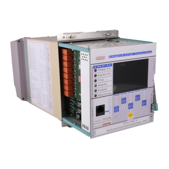
Physical Properties of 400 Series Relays Case The 400 Series case is made of a special alloy in stainless steel. It is covered with modern PVC coating technique. The terminal blocks are fixed to the rear of the box. “Phase Fault” LED “Phase Fault”... -
Page 21: Power Led
Power LED Power LED indicates the presence of healthy auxiliary supply to the 400 Series relay. Internal Error LED Internal Error LED Indicated with “Internal Error” label on the front panel of the relay, LED goes active in red colour if any internal errors are detected... -
Page 22: Device Label
3.15 Device Label 400 Series order code, serial no. and contains all information that must be present on the relay according to standards.Moreover Device label is indelible. Image 3.2 Rear View 3.16 Case Earthing Screw Maximum operation safety is achieved via grounding of this earthing screw, which is the terminal point for the conductance continuity of the case and the internal unit construction. -
Page 23: Circuit Diagram
Image 3.3 Internal & External Units 3.19 Circuit Diagram The circuit diagram of the device is fixed on the relay case. Users do not need to keep documents for basic cabling duties on the field thanks to this inerasable diagram. 3.20 Internal Unit The internal unit houses the entire electronic systems, making it possible to replace the whole unit within seconds without having to black out the system. -
Page 24: Case Earthing Continuity Contact
3.23 Case Earthing Continuity Contact Provides the earthing continuity of the internal unit to the casing. The low-resistance spring contact is rated for prospected earth fault current. 3.24 Faraday Cage Digital signal processors, microprocessors and other critical components are safely embedded within the Faraday cage, clear of wave or field effects that may jeopardize the performance of the relay... -
Page 25: Unit Terminal Blocks
High-endurance internal unit tracks provide robust draw-in and draw-out operation of the internal unit. 3.27 Internal Unit Locking Mechanism As a subsystem of the patented DDS (DEMA Draw out System) technology, internal unit locking mechanism provides locking and drawing out of the internal unit with ease. Locking ensures safe electrical contacts. -
Page 26: Mounting Screws For The Cover
3.30 Mounting Screws for the Cover The cover is mounted onto the case via these screws. Screws are permanently fixed on the case. 3.31 Terminal Plugs Plugs make the electrical connection by locking to the sockets when the internal unit is drawn into the case. -
Page 27: Main Menu
Main Menu This section introduces the Main menu of DPM 400 Protection Relay. Main menu is the interface where the protection settings on the device, general device settings, basic component measurements and breaker positions are observed. When the physical connections of the device are completed and energized, home screen is seen in the figure This document has been prepared in accordance with the SW_1.1.15.2 software version. -
Page 28: Informations
The letter C (Committing) indicates that the setting change was loaded and saved into the system. The letter W (Write) indicates that there are pending changes to the device. The Main Menu Screen consists of the following subtitles: • Information •... - Page 29 control and device interface, or a monitoring vehicle or transformer center level, e.g. It is used for monitoring and reporting with IEC 61850 protocol. All data under the measurements heading refers to the values on the primary side by looking at current and voltage transformer ratios.( Main Menu >...
-
Page 30: Input Monitoring
There are 8 Digital Inputs (20-264V AC / DC) in order to adapt to all kinds of applications in 400 series protection relays. In case of use of the I/O card, 10 Inputs are added to the CPM, VPM and DPM. Inputs are optically isolated and programmable. The display on the device is read-only;... -
Page 31: All Fundamental Measurements
4.2.3 All Fundamental Measurements All basic component measurements page of the device shows the current, voltage and frequency values obtained by harmonizing the measurement data of the line to which it is connected. The display on the device is read-only; does not allow data entry. Image 4-5 : All Fundemental Measurements... -
Page 32: All Rms Measurements
All parameters in the Fundamental Measurements display are described below: IR: R Phase current value and phase angle IS: S Phase current value and phase angle IT: T Phase current value and phase angle I0: Zero-component current value and phase angle I1: Correct component current value and phase angle I2: Negative component current value and phase angle % (I2 / I1): Error rate... -
Page 33: Rms Currents
All Rms Measurements 4.2.5 RMS Currents ”RMS Current“ values displayed on the screen is used according to user or field requirements. This screen includes 3 Phase + Neutral RMS currents as well as their phase angles and frequency. The display of RMS currents is as follows: RMS Current Display 4.2.6 Phase-Neutral Voltages... -
Page 34: Phase-Phase Voltages
4.2.7 Phase-Phase Voltages ” Phase-Phase Voltage “ values displayed on the screen is used according to user or field requirements. In this screen, V voltage values and their phase angles and frequency values are given. The display for Phase-Neutral Voltages is as follows: Image 4-9 Phase-Neutral Voltages 4.2.8 I0 - I1 - I2 currents refer to zero, positive and negative sequence currents respectively. -
Page 35: Thermal Overload
4.2.9 V0 - V1 - V2 voltage values, three-phase voltages are converted into zero, positive and negative components. The voltages V0 - V1 - V2 refer to zero, positive and negative component voltages, respectively. The use of these voltages for short-circuit calculations increases efficiency. -
Page 36: Power Measurements
Phase-Neutral Voltages 4.2.11 Power Measurements It shows the total power values of the load in the three phases to which the device is connected, depending on the character of the load. These are; P: Actual (Active) Power (W) Q: Virtual (Reactive) Power (Yes) Q: Visible (Real) Power (VA) Cos): Power Factor (PF) PE: Wattmetric Earth Fault Power (W) -
Page 37: Led States
Phase-Neutral Voltages 4.2.12 LED States The status of the 10 programmable LEDs in the relay can be viewed from the following screen of the device. LED states also appear embedded on the Home page. The names of these LEDs can be changed under the configuration menu. (Main Menu> Configuration> Led Settings / Writings) LED States Display 4.2.13... -
Page 38: Instant Max Currents
On-screen tripping time, switch-off time and arc time are the time calculated from the position inputs of the circuit breaker. The breaker numerator gives the number of tripping of the breaker in total. ∑A IR, ∑A IS, ∑A IT values indicate the sum of currents that the circuit breaker is subjected to per phase at the time of failure;... -
Page 39: Demand Measurements
Instant Max Currents Display 4.2.15 Demand Measurements Demand values are used to ignore the sudden changes in the measured analog signals while monitoring the long term values for the input signal. Demand values are the average values of the measured signal in an adjustable demand range. All Demand Measurements Display 4.2.16 Energy... -
Page 40: Analog Ma Input
The display of energy measurements is as follows. Energy Metrics Screen 4.2.17 Analog mA Input It is the input in which the Analog 4-20 mA signal is connected to the terminals 48 and 49 of the terminal block X03 of the device. The display of the analog mA input is as follows. - Page 41 Protection Settings Current Protection Settings Voltage Protection Settings Frequency Protection Settings Power Protection Settings General Protection Settings Information about the guards for each of these headings will be reviewed in the following pages. The login page of the protection settings is as follows. Protection Settings Display In the figure above the 'Change Group ' button is used to change protection settings only in groups.
-
Page 42: Protection And Reset Curves
400 Series units are used in the same selectivity scheme with older models of protection relays such as electromechanical relays. The wide setting ranges make 400 Series compatible with most of the protection and selectivity schemes currently in use worldwide. -
Page 43: Iec Inverse Time Protection Curves
�� ������ t= [ + C] × RTMS 1 − ( Universal Formula for Reset Curves Eğri Tipi Koruma Eğrisi Parametreleri Reset Eğrisi Parametreleri Uygulanan α (Açma α (Reset Ayar Aralığı Ayar Aralığı Standart Açıklama Kısaltma Reset Tipi Faktörü) Faktörü) Short Time Inverse IEC STI 0.05 s... - Page 44 TMS Time Multiplier Setting (-). Curve Type Trip Delay Formula Reset Delay Setting Zone 0.05 s IEC STI t= [ ] ×TMS = ������ ( 0.04 − 100 ) �� �� ���������� 0.04 Short Time Inverse IEC SI 0.14 s t= [ ] ×TMS ��...
-
Page 45: Iec Thermal Overload Protection Curves
4.3.1.2 IEC Thermal Overload Protection Curves IEC Thermal Overload Protection formula and sample curves according to this formula are given below. Formula characteristic is determined by the Te, k, Iθ, %θp and %θtrip parameters. When setting ranges for these parameters are considered, it is calculated that 400 Series relay can run 1,540,000 unique IEC Thermal Overload Protection curves;... - Page 46 t Trip time delay (minute). Te Thermal Constant (minute); setting range: (1-200) min, in 1 min steps. k Trip Threshold Translation Constant (-); setting range: (1.00-1.50), in 0.01 steps. I RMS value of load current (A). Iθ Set current (A); setting range: (0.10-3.20) In, in 0.01 In steps. %θp Overload Pre-heating (%);...
-
Page 47: Ansi / Ieee Inverse Time Protection Curves
4.3.1.3 ANSI / IEEE Inverse Time Protection Curves “IEEE (The Institute of Electrical and Electronics Engineers, Inc.) C37.112-2006: IEEE Standard Inverse-Time Characteristic Equations for Overcurrent Relays - Description” standard describes the protection curves named as below. 1. IEEE MI: IEEE Moderately Inverse Curve. 2. -
Page 48: Custom Protection Curves
ANSI / IEEE Inverse Time Delay Curves (TMS=1) 4.3.1.4 Custom Protection Curves 400 Series Special Curves include inverse protection curves for electromechanical relays, constant time characteristic and reset curves. These curves are listed below. 1. SA Semic: Semiconductor Protection Curve. - Page 49 Universal trip time delay formula is given above, while special curve parameters are given on the below table. t Trip delay (s). A A constant for the characteristic (s). I Momentary current (A). Is Set current threshold (A). α A constant for the characteristic (-). B A constant for the characteristic (s).
- Page 50 Custom Delay Curves(TMS=1)
-
Page 51: Definite Time Protection And Reset Delays ( Dmt )
4.3.1.4.1 Definite Time Protection and Reset Delays ( DMT ) DMT characteristic is used for obtaining constant trip and reset delays. There are no parameters for the DMT characteristic other than the constant trip or reset delay. Characteristic notation is as follows: e.g., t = DMT 0.25 s. The image below shows the DMT characteristics for given current values. -
Page 52: Inverse Definite Time Reset Curves ( Idmt )
400 Series protects. The RIDMT parameters differ with the tripping curve they are based on. The table 400 Series Protection and Reset Curves Parameters on page 16 shows these parameters. -
Page 53: Current Protection Settings
4.3.2 Current Protection Settings Phase overcurrent protection settings are located on the device under this sections: Menu> Protection Settings> Current Protection Settings. Relay protection of the line / motor current protection briefly; operates according to the principle of deactivating the protected part by comparing the current information to the relay with the current information assigned in the protection functions The function symbols in the device setting screen are displayed according to IEC 61850, IEC 60617 or IEEE ANSI standards according to user selection. -
Page 54: P – Phase Overcurrent Protection
50/51P – Phase Overcurrent Protection 4.3.2.1 Phase overcurrent protection settings are located on the device under this sections: Main Menu> Protection Settings> Current Protection Settings> Phase Overcurrent Protection In the case of phase overcurrent protection, the protection is activated when the current value exceeds the set current value. -
Page 55: Protection
The settings that can be made in the menu are described below. 4.3.2.1.1 Protection It can be selected ‘Active’ or ‘Passive’.According to the treshold situation, the protection is activated in the active state and disabled in the passive state. 4.3.2.1.2 Start Value The display shows how many times the nominal current value starts when the protection is active. -
Page 56: Reset Delay
curves and their parameters are examined in Main Menu> Protection Settings> Protection and Reset Curves. 4.3.2.1.7 Reset Delay According to the menu settings, It was selected to count the DMT (constant time) reset time (0.04 s) after the current has dropped below 5.00 In without exceeding 5.00 In and without breaker tripping. -
Page 57: Protection
Earth Overcurrent Protection IEC 61850 IEC 60617 IEEE-ANSI EŞİK-1 EI_PIOC_1 Ie> 50/51N-I-1 EŞİK-2 EI_PIOC_2 Ie>> 50/51N-I-2 EŞİK-3 EI_PIOC_3 Ie>>> 50/51N-I-3 EŞİK-4 EDI_PIOC_1 Ie_d> 50/51N-DI-1 EŞİK-5 EDI_PIOC_2 Ie_d>> 50/51N-DI-2 Earth Overcurrent Protection Function Symbols The menu view is as follows. Earth Overcurrent Protection Screen The settings available in the menu are as follows. -
Page 58: Start Value
4.3.2.2.2 Start Value The display shows how many times the nominal current value starts when the protection is active. Selection is made in (0.05-35) In range 4.3.2.2.3 Delay Type The type of delay curve for protection is assigned from this option. This curves can be selected from tables : Menu>... -
Page 59: Reset Delay
4.3.2.2.7 Reset Delay According to the menu settings, It was selected to count the DMT (constant time) reset time (0.04 s) after the current has dropped below 5.00 In without exceeding 5.00 In and without breaker tripping. Thus, after the current falls below the threshold, 40 ms will be counted. If the threshold is not exceeded until the end of this period, the protection function trip time counter will be reseted. -
Page 60: Protection
heat up and cause faults in a short time is solved by thermal overload protection functions in modern systems. Thermal Overload Protecions are shown in IEC 60617 Standards with I >-A; in IEC 61850 Θ Standards with PH_PTTR_A; in IEEE / ANSI Standards with 49-A. Thermal Overload Protection IEC 61850 IEC 60617... -
Page 61: Trip Θ
transformer with current transformers 30 A / 5 A is requested. The primary rated current of the transformer is calculated as 26.8 A and value of I > is set 0.89In from the ratio of 26.8 A / Θ 30 A. IΘ> adjustment range is (0.10 – 3.20) I 4.3.2.3.3 Warming represents the constant time and is given in minutes. -
Page 62: Alarm Θ
Alarm Θ 4.3.2.3.7 Just like Trip Θ, it represents a warming limit in percentage; however, it is used to warn the user or the facility instead of the breaker tripping. The function value can be set in the range of 50% - 200% as long as it is under Trip Θ value. Thermal Alarm warning can be monitored in two ways. -
Page 63: Protection
Directional Phase Overcurrent Protection Screen Directional Phase Overcurrent Protection Screen The settings that can be made in the menu are described below. Hata! Yer işareti tanımlanmamış. 4.3.2.4.1 Protection It can be selected ‘Active’ or ‘Passive’. According to the treshold situation, the protection is activated in the active state and disabled in the passive state... -
Page 64: Start Value
4.3.2.4.2 Start Value The display shows how many times of the nominal current value starts when the protection is active. Selection is made in (0.05-35) In range. 4.3.2.4.3 Delay Type The type of delay curve for protection is assigned from this option. These curves can be selected from the Main Menu>... -
Page 65: Reset Delay
curves and their parameters are examined in Main Menu> Protection Settings> Protection and Reset Curves. 4.3.2.4.7 Reset Delay According to the menu settings, exceeding 5.00 In and without breaker tripping, It was selected to count the DMT (constant time) reset time (0.04 s) after the current has dropped below 5.00 In. -
Page 66: Measurement Mode
4.3.2.4.12 Measurement Mode The measurement mode can be selected as RMS or Basic Component. The basic component measurement is selected to use harmonic-free measured values. The RMS measurement is selected to use the values calculated by taking the square root of the mean of the squares of the measured values. -
Page 67: Protection
Directional Earth Overcurrent Protection Display The settings that can be made in the menu are described below. 4.3.2.5.1 Protection It can be selected ‘Active’ or ‘Passive’.According to the treshold situation, the protection is activated in the active state and disabled in the passive state. 4.3.2.5.2 Start Value The display shows how many times the nominal current value starts when the protection is... -
Page 68: Operate Delay
4.3.2.5.5 Operate Delay The operation delay is the value that determines the characteristic of the protection curve with the delay type. Operation delay can take a value between (0.02-200)s if the delay type is selected as DMT. If the delay type is selected as one of the IDMT curves, the delay is expressed by the term “TMS”... -
Page 69: Rtms
4.3.2.5.9 RTMS Reset Curves are the ‘Reset Time Multiplier’ used in the Universal Formula. The Reset Type is activated when it is selected as IDMT. The setting range of the multiplier can be selected in the range (0,025 – 5). 4.3.2.5.10 Trip Zone Trip area can be selected in forward and reverse direction with ±... -
Page 70: Protection
poles in a distribution center and opening of the breaker, stopping the engine in the event that the water supply of a water pump is depleted. In order for the phase low current protection function works properly, any of the programmable inputs must be assigned the 52a function. -
Page 71: Start Value
4.3.2.6.2 Start Value The display shows how many times the nominal current value starts when the protection is active. Selection is made in (0.05-1)I In range 4.3.2.6.3 Operate Delay The operation delay determines the characteristic of the protection curve with the delay type. The delay type is DMT characteristic, the delay can be in the range of 0.02 - 200 s. -
Page 72: Negative Sequence Overcurrent Protection
measurement is selected to use the values calculated by taking the square root of the mean of the squares of the measured values. This value is also called Active or Effective value. 4.3.2.7 46-Negative Sequence Overcurrent Protection Phase overcurrent protection settings are located on the device under Menu> Protection Settings>... -
Page 73: Protection
Negative Sequence Overcurrent Protection Display 4.3.2.7.1 Protection It can be selected ‘Active’ or ‘Passive’.According to the treshold situation, the protection is activated in the active state and disabled in the passive state. 4.3.2.7.2 Start Value The display shows how many times the nominal current value starts when the protection is active. -
Page 74: Reset Delay
Reset type and time indicates that, the protection function which starts counting with a current above the specified current threshold, shows the curve and value that determines the duration of the failure if the current falls below the threshold without tripping. The reset type can be selected as DMT (fixed time) and IDMT (reverse constant time) according to the selected protection curve type. -
Page 75: Over Voltage Protection
Voltage Protection Settings Display 59 – Over voltage Protection 4.3.3.1 The overvoltage protection settings are located Main Menu> Protection Settings> Voltage Protection Settings> Overvoltage Protection. The protection is activated if the mains voltage exceeds the specified protection range. It works with phase-phase or phase-neutral voltage information. The voltage of each phase is monitored separately. -
Page 76: Protection
OverVoltage Protection Display The settings that can be made in the menu are described below. 4.3.3.1.1 Protection It can be selected ‘Active’ or ‘Passive’.According to the treshold situation, the protection is activated in the active state and disabled in the passive state. 4.3.3.1.2 Start Value It is the screen in where the protection of the phase-to-neutral voltage value is set when the... -
Page 77: Hysteresis
until the end of this period, the protection function trip time counter will be reseted. Reset delay thresholds are in the range of (0-60). 4.3.3.1.5 Hysteresis It allows the selection of the minimum and maximum values for the protection to be activated by entering the value in percentages and the same value being switched off in percentage. - Page 78 Under Voltage Protection IEC 61850 IEC 60617 IEEE-ANSI EŞİK-1 PHI_PIUV_1 U< 27-I-1 EŞİK-2 PHI_PIUV_2 U<< 27-I-2 Under Voltage Protection Function Symbols The menu consists of nine lines and the menu display is as follows. Under Voltage Protection Display Under Voltage Protection Display...
-
Page 79: Protection
4.3.3.2.1 Protection It can be selected ‘Active’ or ‘Passive’.According to the treshold situation, the protection is activated in the active state and disabled in the passive state. 4.3.3.2.1 Start Value It is the screen where the protection of the phase-to-neutral voltage value is set when the protection is active. -
Page 80: Hysteresis
4.3.3.2.7 Hysteresis It allows the selection of the minimum and maximum values for the protection to be activated by entering the value in percentages and the same value being switched off in percentage. For example, if the undervoltage protection start value is set to 100 V, the hysteresis value is set to 5%, the protection is activated when the protection falls below 95V;... -
Page 81: Protection
Negative Component Overvoltage Protection Display 4.3.3.3.1 Protection It can be selected ‘Active’ or ‘Passive’.According to the treshold situation, the protection is activated in the active state and disabled in the passive state. 4.3.3.3.2 Start Value It is the screen where the voltage value of U2 is set when the protection is active.It can select in range of (1-130)V 4.3.3.3.3 Operate Delay... -
Page 82: Hysteresis
exceeded until the end of this period, the protection function trip time counter will be reseted. Reset delay thresholds are in the range of (0-60). 4.3.3.3.5 Hysteresis It allows the selection of the minimum and maximum values for the protection to be activated by entering the value in percentages and the same value being switched off in percentage. -
Page 83: Protection
Notr Over Voltage Protection Display The settings that can be made in the menu are described below. ProtectionHata! Yer işareti tanımlanmamış. 4.3.3.4.1 It can be selected ‘Active’ or ‘Passive’.According to the treshold situation, the protection is activated in the active state and disabled in the passive state. 4.3.3.4.2 Start Value It is the screen where the voltage value of neutral is set when the protection is active. -
Page 84: Hysteresis
after the current falls below the threshold, 40 ms will be counted. If the threshold is not exceeded until the end of this period, the protection function trip time counter will be reseted. Reset delay thresholds are in the range of (0-60). 4.3.3.4.5 Hysteresis It allows the selection of the minimum and maximum values for the protection to be activated... -
Page 85: U – Under Frequency Protection
81U – Under Frequency Protection 4.3.4.1 The overvoltage protection settings are located Menu> Protection Settings> Frequency Protection Settings> Under Frequency Protection Working principle; The measured frequency value is the activation of the protection when the assigned protection falls below the threshold. The time characteristic is DMT (constant time) characteristic. -
Page 86: Protection
Under Frequency Protection Display The settings that can be made in the menu are described below. 4.3.4.1.1 Protection It can be selected ‘Active’ or ‘Passive’.According to the treshold situation, the protection is activated in the active state and disabled in the passive state. 4.3.4.1.2 Start Value It is the screen where the Under Frequency Protection is set when the protection is active. -
Page 87: Hysteresis
According to the menu settings, exceeding 45Hz and without breaker tripping, It was selected to count the DMT (constant time) reset time (0.04 s) when the frequency does not fall below 45Hz In. Thus, after the current falls below the threshold, 40 ms will be counted. If the threshold is not exceeded until the end of this period, the protection function trip time counter will be reseted. -
Page 88: Protection
The menu view is as follows. The menu consists of five lines. Over Frequency Protection Display The settings that can be made in the menu are described below. 4.3.4.2.1 Protection It can be selected ‘Active’ or ‘Passive’.According to the treshold situation, the protection is activated in the active state and disabled in the passive state. -
Page 89: Hysteresis
According to the menu settings, exceeding 45Hz and without breaker tripping, It was selected to count the DMT (constant time) reset time (0.04 s) frequency is above 45Hz. Thus, after the current falls below the threshold, 40 ms will be counted. If the threshold is not exceeded until the end of this period, the protection function trip time counter will be reseted. -
Page 90: Protection
EŞİK-1 I_PFRC_1 (df/dt)> 81R-I-1 EŞİK-2 I_PFRC_2 (df/dt)>> 81R-I-2 EŞİK-3 I_PFRC_3 (df/dt)>>> 81R-I-3 EŞİK-4 I_PFRC_4 (df/dt)>>>> 81R-I-4 EŞİK-5 I_PFRC_5 (df/dt)>>>>> 81R-I-5 EŞİK-6 I_PFRC_6 (df/dt)>>>>>> 81R-I-6 Rate of Change of Frequency Protection Function Symbols The menu view is as follows. The menu consists of four lines. Rate of Change of Frequency Protection Display 4.3.4.3.1 Protection... -
Page 91: Operate Delay
4.3.4.3.3 Operate Delay The operation delay is the value that determines the characteristic of the protection curve with the delay type. In the case of Rate of Change of Frequency Protection, the delay type must be DMT. This delay may take a value between (0.08 – 200) s 4.3.4.3.4 Reset Delay According to the menu settings, It was selected to count the DMT (fixed time) reset time... -
Page 92: Op – Directional Active Over Power
Power Protection Settings Display Directional Active-Reactive Over and Low Power Protection Vectors 32OP – Directional Active Over Power 4.3.5.1 The Directional Active Over Power settings are Main Menu> Protection Settings> Power Protection Settings> Directional Active Over-Power Protection This protection starts when the total active power reading of the device exceeds the starting value. -
Page 93: Protection
curve type and performs a trip after the operation delay time. The direction of the protection is determined using the direction angle value under protection settings. Directional Active Over Power is indicated by P>, P>> in IEC 60617; PI_PDOP_1 ve PI_PDOP_2 in IEC 61850;... -
Page 94: Direction Angle
It is the screen where the Directional Active Over Power’s treshold is set when the protection is active. Selection is in the range of 10000x5W - 1x5W. 4.3.5.1.3 Direction Angle It is the screen where Directional Active Over Power is set and angle of direction is selected. –... -
Page 95: Protection
YÖNLÜ AKTİF AŞIRI DÜŞÜK KORUMASI IEC 61850 IEC 60617 IEEE-ANSI EŞİK-1 PI_PDUP_1 P< 32UP-I-1 EŞİK-2 PI_PDUP_2 P<< 32UP-I-2 Directional Active Under Power Function Symbols The menu view is as follows. The menu consists of eight lines. Directional Active Under Power Protection Display 4.3.5.2.1 Protection It can be selected ‘Active’... -
Page 96: Direction Angle
4.3.5.2.3 Direction Angle It is the screen where Directional Active Over Power is set and angle of direction is selected. – 359 Selection is made between (0 4.3.5.2.4 Operate Delay The operation delay is the value that determines the characteristic of the protection curve with the delay type. -
Page 97: Protection
32OQ – Directional Reactive Over Power Hata! Yer işareti tanımlanmamış. 4.3.5.3 The Directional Active Over Power settings are Main Menu> Protection Settings> Power Protection Settings> Directional Reactive Over Power Directional Active Over Power is indicated by Q> ve Q>> in IEC 60617; QI_PDOP_1 ve QI_PDOP_2 in IEC 61850;... -
Page 98: Start Value
4.3.5.3.2 Start Value It is the screen where the treshold of Directional Reactive Over Power is set when the protection is active. This level can be selected in the range of 10000x5W – 1x5W 4.3.5.3.3 Direction Angle It is the screen where Directional Reactive Over Power r is set and angle of direction is –... -
Page 99: Protection
Directional Active Over Power is indicated by Q<, Q<< in IEC 60617; QI_PDUP_1, QI_PDUP_2 in IEC 61850; 32UQ-I-1, 32UQ-I-2 in IEEE/ANSI Standards Directional Reactive Under Power Protection IEC 61850 IEC 60617 IEEE-ANSI EŞİK-1 QI_PDUP_1 Q< 32UQ-I-1 EŞİK-2 QI_PDUP_2 Q<< 32UQ-I-2 Directional Reactive Under Power Function Symbols The menu consists of eight lines. -
Page 100: Direction Angle
4.3.5.4.3 Direction Angle It is the screen where Directional Reactive Under Power is set and angle of direction is – 359 selected.This selection can be in (0 ) range 4.3.5.4.4 Operate Delay The operation delay is the value that determines the characteristic of the protection curve with the delay type. -
Page 101: N – Wattmetric Earth Protection
32N – Wattmetric Earth Protection 4.3.5.5 The Directional Active Over Power settings are Menu> Protection Settings> Power Protection Settings> Wattmetric Earth Protection Wattmetric soil protection (32N) is used to detect the negative or positive residual power direction. In the selection of the negative alternance voltage, if the angle difference between the negative alternance voltage and the current is in the predefined direction (forward or reverse), 32N gives the trip signal after a certain time delay. -
Page 102: Protection
Wattmetric Earth Fault Protection Display 4.3.5.5.1 Protection It can be selected ‘Active’ or ‘Passive’.According to the treshold situation, the protection is activated in the active state and disabled in the passive state 4.3.5.5.2 Start Value It is the screen where the treshold of Wattmetric Earth Protection is set when the protection is active. -
Page 103: Hysteresis
threshold is not exceeded until the end of this period, the protection function trip time counter will be reseted. Reset delay thresholds are in the range of (0-60). 4.3.5.5.7 Hysteresis It allows the selection of the minimum and maximum values for the protection to be activated by entering the entered value in percentages and the same value being switched off in percentage. -
Page 104: Number Of Valid
The number of cycles used to calculate the rate at which frequency change rate protection is used. Number of ValidHata! Yer işareti tanımlanmamış. 4.3.6.2.3 It is the number of controls used to calculate speed in frequency change rate protection. 4.3.6.2.4 Inhibit>20 Hz/s It is the setting used to prevent protection when the speed is above 20 Hz / s in frequency change rate protection. -
Page 105: Cold Load Pickup
4.4.7 Cold Load Pickup Under Construction 4.4.8 Blocking Selectivity Settings Under Construction 68 –Inrush Blocking 4.4.9 Under Construction 4.4.10 Delaying Logic Selectivity Setttings Under Construction 51V – Voltage Controlled Overcurrent 4.4.11 Under Construction 4.4.12 VT Supervision ......................under construction 4.4.13 CT Supervision ...................... -
Page 106: System Settings
4.4.18 Switch on to Fault --------------------------------------------------------------------------- Under Construction 4.4.19 Auto-reclosing ------------------------------------------------------------------------------- Under Construction 4.4.20 Analog mA Input ---------------------------------------------------------------------------- Under Construction 4.5 System settings This is the screen where the system settings of the device are made. It is located under the main menu title. -
Page 107: Function Symbol
Language Selection Display 4.5.2 Function Symbol The selection of the protection types in the device is made from this screen. IEC 61850, IEC 60617 or IEEE-ANSI function symbols can be selected. The protection designation in the protection setting menus is made according to the selection of the function symbol. The function symbol settings are listed under yer Main Menu>... -
Page 108: Date-Time
IEC 61850 IEC 60617 IEEE-ANSI EŞİK-1 PHI_PIOC_1 I> 50/51P-I-1 Example Function Symbol Representation 4.5.3 Date-Time ..........................This is the screen where the regional date and time settings are made. It is important to transfer the time data to the user in the follow-up of the event records. Date - time settings are listed under ”Main Menu>... -
Page 109: Lcd Lighting Time
Nominal Frequency Setting Display 4.5.7 LCD Lighting Time It is the screen in which the LCD display remains on in standby mode. The LCD lighting time settings are listed under Main Menu> System Settings> LCD Lighting Time on the device and are made in (0 - 60) minutes. -
Page 110: Main Screen Measurement
Default Screen Timeout Display 4.5.10 Main Screen Measurement Here, the selection of the voltage or current measurements to be displayed is shown in the field in the following screen. The main screen measurement selection is located on the device under “Main Menu> System Settings> Main Screen Measurement” Main Screen Measurement Display Configuration It is the screen where the information required for the field installation of the device is... -
Page 111: General Options
Settings altında on the device. The following options are available in the configuration settings menu: • General Options • Measurement Settings • Waveform Recording • Time Synchronization • CT / VT Settings • LED Settings • LED Posts • Group Settings •... -
Page 112: Measurement Settings
• Current Phase Rotation It is used to indicate that the current terminals connected to the relay come from different phases. It allows to change the rotations of the phases without changing the cable in the field. This rotation; It can be selected as R-S-T or R-T-S. •... -
Page 113: Time Synchronization
4.6.4 Time Synchronization Under Construction 4.6.5 CT / VT Settings It is the display of current and voltage transformers that provide current and voltage information to the device and how phase transforms of voltage transformers are selected. CT / VT Settings are located on the device under Main Menu> Configuration Settings> CT / VT Settings. - Page 114 The voltage transformer connected to the device is the screen where the primary residual voltage is assigned. This setting is in the range of (0.1 - 1000) kV. • Residual VT Secondary The voltage transformer connected to the device is the display where the secondary residual voltage is assigned.
-
Page 115: Alarm Settings
4.6.9 Output Relays -------------------------------------------------------------------------------- Under Construction 4.6.10 Group Settings ------------------------------------------------------------------------------- The settings to be made in a protection relay used in the ring system vary according to the direction of feeding of the ring. If two different sets of settings are created in the protection relay by taking this situation into consideration, if the feeding direction of the ring changes, the settings of the relevant relays can be made quickly by selecting the appropriate one of the pre-set setting groups. -
Page 116: Communication Settings
Alarm Settings Display 4.6.12 Communication Settings Under Construction 4.6.13 Ethernet Interface Settings The device has two Ethernet Ports, one on the front and one on the back. The Ethernet Port on the front of the device has a fixed IP address (192.168.2.215) for easy setup and access for all relays. -
Page 117: Recordings
Ethernet Interface Settings Display Rear Port Display Recordings Under Construction Order Menu Under Construction... -
Page 118: Active Functions
Active Functions Under Construction 4.10 Function Test Under Construction 4.11 Authorization Under Construction...
Need help?
Do you have a question about the 400 Series and is the answer not in the manual?
Questions and answers