Kärcher SGV 6/5 Service Manual
Hide thumbs
Also See for SGV 6/5:
- User manual (22 pages) ,
- Manual (372 pages) ,
- Operation manual (56 pages)
Table of Contents
Advertisement
Advertisement
Table of Contents

Related Manuals for Kärcher SGV 6/5


Summary of Contents for Kärcher SGV 6/5
- Page 1 SGV 6/5 SGV 8/5 Service Manual English 5.906-590.0 Rev. 01 (05/17)
-
Page 2: Table Of Contents
Contents Preface Safety instructions Hazard levels Description in this service manual Service groups Functional group structure Textual description Technical Features Proper use Cleaning of various materials Refreshing textiles Cleaning of Coated or Lacquered Surfaces Detergent Field of application Safety installations Safety catch Type plate Overview of the appliance... - Page 3 ACAF Uninstall / install exhaust filter ACST Uninstall/ install suction turbine 050 Maintenance and inspection 060 Error diagnosis 070 Peculiarities/ others AD Service group steam system 010 Safety information 020 Overview 030 Function 040 Service activities ADSO Uninstall / install probe water level ADDD Uninstall / install pressure valves steam boiler ADAT Open / close carrier ADWP Uninstall / install water pump...
- Page 4 Table of measurement values General troubleshooting for steam vacuum cleaners and steamers Overview circuit boards µC-Card Power Card Technical Documentation Technical specifications Circuit diagram Performance electronics Control electronics English 5.906-590.0 Rev. 01 (05/17)
-
Page 5: Preface
Preface Good service work requires extensive and practice-orient- ed training as well as well-structured training materials. Hence we offer regular basic and advanced training pro- grammes covering the entire product range for all service engineers. In addition to this, we also prepare service manuals for im- portant appliances - these can be initially used as instruc- tion guides and later on as reference guides. -
Page 6: Description In This Service Manual
Description in this service manual Service groups Example: Install/uninstall ANRA wheel axle Install/uninstall wheel axle Service group Component Activity Observe the allocation of service groups to the appliance components in the overview diagram in Chapter "Overview over the service and functional groups". Functional group structure Safety instructions Overview... -
Page 7: Technical Features
If you require further information please request the prod- uct information sheet and the DIN safety data sheet for the respective cleaning agent. Field of application This service manual applies to the following appliances: SGV 6/5 SGV 8/5 *AUS English 5.906-590.0 Rev. 01 (05/17) -
Page 8: Safety Installations
Safety installations Safety devices serve to protect the user and must not be rendered in operational or their functions bypassed. Observe safety information in the chapters! Safety catch The handle is equipped with a safety catch on the – steam switch, which prevents accidental steam re- lease. -
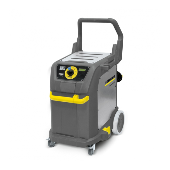
Page 9: Overview Of The Appliance
SGV 8/5) 12 Holder for floor nozzle (parking position) 13 Steering roller with fixed position brake 14 Detergent container (SGV 8/5) Container for detergent spray bottle (SGV 6/5) 15 Recessed grip 16 Fresh water container 17 Accessory outlet 18 Locking mechanism of the accessory plug... -
Page 10: Operating Field
Operating field 1 0/OFF 2 Operating mode: Cold water/suction operation 3 Operating mode: Steam/hot water/cold water/suction operation (eco!efficiency) 4 Operating mode: Steam/hot water/cold water/suction operation 5 Operating mode: Rinsing (SGV 8/5 only) 6 Operating mode: Detergent/suction operation (SGV 8/ 5 only) 7 Operating mode: Self-cleaning (SGV 8/5 only) 8 Rotating knob 9 Display (SGV 8/5 only) -
Page 11: Ab Service Group Setup
AB Service group setup 010 Safety information WARNING Prior to all work on the appliance, switch off the appliance and pull the power plug. Allow the appliance to cool down prior to performing ser- vice tasks. Observe general safety information! 020 Overview 1 Metal sheet door waste water tank 2 Frame door waste water tank... - Page 12 ABAF Uninstall/install cover fresh water tank ABBF Uninstall/install faceplate fresh water tank ABAM Uninstall / install cover of the detergent tank ABBM Uninstall/install faceplate detergent tank ABSL Uninstall / install hinge band door waste water tank ABRT Uninstall / install frame door waste water tank ABBT Uninstall / install metal sheet door waste water tank ABZH Uninstall / install accessory hook ABZS Uninstall / install the accessory support...
-
Page 13: 030 Function
030 Function The basic unit is characterized by good accessibility and The tanks can be removed from the appliance individually. ease of servicing. It has a self-supporting frame made of The push handle can be dismounted. plastic. Accessory holder, accessory support and cable hooks can Steam boiler, pumps and valves are mounted on a base be replaced. - Page 14 Unscrew the screws. Remove faceplate of the fresh water tank. Loosen the fastening clips. Remove cover of the fresh water tank. Remove the lid from the fresh water reservoir. Pull the elbow out of the retainer. ...
-
Page 15: Abbf Uninstall/Install Faceplate Fresh Water Tank
ABBF Uninstall/install faceplate fresh water tank 1 Screws Unscrew the screws. Remove faceplate of the fresh water tank. 1 Handle 2 Faceplate fresh water tank 3 Screws Unscrew the screws. Remove the handle from the faceplate. ABAM Uninstall / install cover of the detergent tank The procedure conforms to the task: ... -
Page 16: Absl Uninstall / Install Hinge Band Door Waste Water Tank
ABSL Uninstall / install hinge band door waste water tank 1 Screws 2 Hinge band Unscrew the screws. Torx T20 Remove the hinge band. ABRT Uninstall / install frame door waste water tank ABSL Uninstall / install hinge band door waste water tank ... -
Page 17: Abbt Uninstall / Install Metal Sheet Door Waste Water Tank
ABBT Uninstall / install metal sheet door waste water tank ABSL Uninstall / install hinge band door waste water tank ABRT Uninstall / install frame door waste water tank Push all expanding rivets out of the frame. ... -
Page 18: Abzs Uninstall / Install The Accessory Support
Unscrew the screws. Pull the accessory hook out of the retainer. ABZS Uninstall / install the accessory support 1 Screws 2 Accessory support Unscrew the screws. Pull the accessory hook out of the retainer. English 5.906-590.0 Rev. 01 (05/17) -
Page 19: Abkh Uninstall / Install Cable Hook
ABKH Uninstall / install cable hook 1 Screws 2 Cable hook Unscrew the screws. Remove the cable hook from the holder. Note The rotating part of the cable hook is engaged in the retain- er. With sluggish cable hooks, check if the rotating part is pulled out of the retainer. -
Page 20: Absb Uninstall / Install Push Handle
ABSB Uninstall / install push handle ABZH Uninstall / install accessory hook A View from above B Rear view 1 Top screws 2 Screw back / bottom Unscrew the screws at the top and at the back / bottom. ... -
Page 21: Abrh Uninstall / Install Wheels In The Back
Unscrew the hexagon socket screw. Pull the steering roller out of the frame. ABRH Uninstall / install wheels in the back 1 Axle 2 Wheel 3 Safety disc 4 Wheel cap Carefully wedge the wheel cap free. ... -
Page 22: Abdg Uninstall / Install Seal Of The Rear Appliance Cover
Unscrew the screws. Remove the cover towards the back. Unplug the protective conductor cable. Lift the cover over the accessory support and remove it from the appliance. Installation information Ensure the correct seating of the seal during installation. ABDG Uninstall / install seal of the rear appliance cover ... -
Page 23: Abgl Uninstall / Install Appliance Cover On The Left Side
Installation information Ensure the correct seating of the seal during installation. ABGL Uninstall / install appliance cover on the left side 1 Screws Unscrew the screws. Remove appliance cover. Note Protective conductor is inserted on the inside of the device cover. -
Page 24: Absd Unistall / Install Socket
ABSD Unistall / install socket 1 Screws 2 Connection control electrics manual nozzle 3 Conductive bolt 4 Suction hose connection 5 Steam connection Unscrew the screws. Remove the socket from the appliance. Unclip connection control electrics manual nozzle. ... - Page 25 Pull the seal out of the groove. Installation information Ensure the correct seating of the seal during installation. For better visibility, the seal is shown in red. English 5.906-590.0 Rev. 01 (05/17)
-
Page 26: Abtf Uninstall / Install Tank Connection Fresh Water
ABTF Uninstall / install tank connection fresh water ABGL Uninstall / install appliance cover on the left side Remove the fresh water tank from the appliance. Remove the detergent tank from the appliance. 1 Screw 2 Tank connection fresh water tank 3 Support plate 4 Tank connection detergent tank ... -
Page 27: 050 Maintenance And Inspection
050 Maintenance and inspection Service group does not contain any maintenance and in- spection points. 060 Error diagnosis Findings Possible cause Correction Water in the appliance Seal for the rear appliance cover dam- Replace seal. aged. Seal for the left appliance cover dam- aged. -
Page 28: Ac Service Group Suction System
AC Service group suction system 010 Safety information WARNING Prior to all work on the appliance, switch off the appliance and pull the power plug. Allow the appliance to cool down prior to performing ser- vice tasks. Observe general safety information! 020 Overview 1 Grid exhaust opening 2 Casing blower filter... - Page 29 ACAF Uninstall / install exhaust filter ACST Uninstall/ install suction turbine English 5.906-590.0 Rev. 01 (05/17)
-
Page 30: 030 Function
030 Function Flow chart of the air through the suction system: 1 Suction hose 2 Socket 3 Connection hose 4 waste water tank 5 Exhaust filter 6 Suction turbine 1 Suction turbine 2 Waste water tank supply 3 Reed switch 1 Opening for suction turbine 2 Inlet port for waste water 3 Disc... -
Page 31: 040 Service Activities
040 Service activities ACAF Uninstall / install exhaust filter ABGH Uninstall / install appliance cover in the back Push in the locking mechanism of the filter casing and remove the filter casing. Take out the filter inlay. ACST Uninstall/ install suction turbine 1 Grid supply air 2 Lower gasket... - Page 32 1 Turbine cover 2 Screws Unscrew the screws. Remove turbine cover. Remove the suction turbine from the appliance. Separate the electric connectors. Take the connection calbe through the turbine cover. Remove the seals and sealing cone from the suction turbine.
-
Page 33: Maintenance And Inspection
050 Maintenance and inspection Service group does not contain any maintenance and in- spection points. 060 Error diagnosis Findings Possible cause Correction No suction effect. Suction turbine defective. Replace the suction turbine. Connecting piece of the waste water Uninstall suction turbine, clean connect- tank clogged. -
Page 34: Ad Service Group Steam System
AD Service group steam system 010 Safety information WARNING Prior to all work on the appliance, switch off the appliance and pull the power plug. Allow the device to cool down prior to performing any ser- vice tasks. Relieve the high pressure system of all pressure prior to all work on the appliance and the accessories. - Page 35 ADSO Uninstall / install probe water level ADDD Uninstall / install pressure valves steam boiler ADAT Open / close carrier ADWP Uninstall / install water pump ADKP Uninstall / install boiler pump ADMA Uninstall / install solenoid valve ADTW Uninstall / install water shortage thermostat ADTX Activating the reset button thermostat water shortage ADDK Uninstall / install steam boiler English 5.906-590.0 Rev.
-
Page 36: Function
030 Function From the fresh water container, water is pumped into the steam boiler using the boiler pump. The water is heated. When operating the steam switch on the handle, the valves on the steam boiler open. The steam flows through the socket into the connected ac- cessory. -
Page 37: Service Activities
040 Service activities ADSO Uninstall / install probe water level ABGL Uninstall / install appliance cover on the left side 1 Electric connectors 2 Probe water level 3 Nut Separate the electric connectors. Loosen the nuts. Pull out probe. ADDD Uninstall / install pressure valves steam boiler ... -
Page 38: Adat Open / Close Carrier
ADAT Open / close carrier ABGL Uninstall / install appliance cover on the left side 1 Water hoses 2 Cable tie 3 Nut steam connection 4 Hose steam connection Remove tanks. Mark and pull off the hoses. ... -
Page 39: Adwp Uninstall / Install Water Pump
1 Screws 2 Carrier Unscrew the screws. Unplug the protective conductor cable. Open the carrier. ADWP Uninstall / install water pump ABGL Uninstall / install appliance cover on the left side ADAT Open / close carrier 1 Hose water pump in the back 2 Rubber bearing 3 Hose water pump at the top... -
Page 40: Adtw Uninstall / Install Water Shortage Thermostat
ADTW Uninstall / install water shortage thermostat ABGL Uninstall / install appliance cover on the left side ADAT Open / close carrier 1 Screws 2 Holder solenoid valves 3 Covers 4 Nuts 5 Covering plate Unscrew the screws. ... -
Page 41: Adtx Activating The Reset Button Thermostat Water Shortage
1 Reset button Installation information Push in the reset button in order to activate the thermostat water shortage. ADTX Activating the reset button thermostat water shortage Up to the works numbers indicated, proceed as described in the service group in order to reset the reset button. Appliance number Serial number 1.092-000.0... - Page 42 1 Steam boiler 2 Screw connections 3 Low-water thermostat Lift the steam boiler. Disconnect screw connections. Detach the thermostat water shortage. 1 Reset button 2 Cover cap Remove the cover cap. Push in the reset button in order to activate the thermo- stat water shortage.
-
Page 43: Adtx Activating The Reset Button Thermostat Water Shortage
ADTX Activating the reset button thermostat water shortage The accessibility of the reset button was improved, and the cover plate given an extra bore hole. Starting from the works numbers indicated, proceed as de- scribed in the service group in order to reset the reset but- ton. -
Page 44: Addk Uninstall / Install Steam Boiler
ADDK Uninstall / install steam boiler ABGL Uninstall / install appliance cover on the left side ADDD Uninstall / install pressure valves steam boiler ADSO Uninstall / install probe water level ADAT Open / close carrier 1 Electric connectors 2 Nuts 3 Hose clip... - Page 45 1 brown 2 red Note When connecting the steam boiler, observe the various country variants. Measure the connections by means of a clamp meter. Line colour Line cross section (mm²) Heating capacity (W) Current consumption (A) Brown 2000 1000 Japan Line colour...
-
Page 46: Maintenance And Inspection
050 Maintenance and inspection Descaling steam boiler All components used for the descaling process must be WARNING acid-resistant. Prior to all work on the appliance, switch off the appliance Required components: and pull the power plug. Allow the device to cool down prior to performing any ser- Descaling set 2.840-035.0 vice tasks. - Page 47 1 Drain screw Place on a suitable work table. Lay the appliance onto the push handle. Loosen the drain screw. Pierce the complete drilled hole by means of a suitable tool and remove lime deposits. 1 Drain hose ...
-
Page 48: Error Diagnosis
Disassembly Drain the descaler into the provided catch pan via the drain hose. Completely fill the steam boiler with water and rinse it 2 to 3 times. No residue of the descaler must remain in the steam boiler. -
Page 49: Af Service Group Control Unit
AF Service group control unit 010 Safety information WARNING Relieve the high pressure system of all pressure prior to all Prior to all work on the appliance, switch off the appliance work on the appliance and the accessories. and pull the power plug. CAUTION Allow the appliance to cool down prior to performing ser- Risk of damage by electrostatic discharge (ESD)! Take... -
Page 50: Function
030 Function The service group does not contain any peculiarities. 040 Service activities AFDH Uninstall / install steam nozzle in the back 1 Hose 2 Screws 3 Casing 4 Housing top Unscrew the screws. Turn over casing. Remove the top part of the casing. 1 Steam hose 2 Hose clamp 3 Steam nozzle... -
Page 51: Afdg Uninstall / Install Steam Nozzle In The Front
1 Plate 2 Casing 3 Suction hose 4 Holes Installation information Place the plate into the second groove of the suction hose. The drilled hole in the plate and the drilled hole in the casing must be on the same side. 1 Hose 2 Screws 3 Casing... - Page 52 1 Trigger lock 2 Steam hose 3 Hose clamp 4 Steam nozzle Remove the trigger lock. Remove hose clamp. The hose clamp is destroyed upon removal. Pull the steam hose off the steam nozzle. 1 Lock Remove the lock. 1 Screws ...
- Page 53 1 Steam hose 2 Wiring 3 Hose clamp 4 Steam nozzle 5 Screws 6 Casing 7 Intake Slide the steam nozzle into the casing from the front. Screw down the steam nozzles using screws. Slide the hose clamp onto the hose. ...
-
Page 54: Afms Uninstall /Install Microswitch
1 Hand wheel 2 Casing 3 Electric connectors Push the electrical socket plug connection as far as possible into the casing. Insert the handwheel. NOTE Mind the installation position. 1 Casing shell 2 Casing shell Down Place the upper casing part onto the lower casing part and screw them together. -
Page 55: Maintenance And Inspection
1 Electric connectors 2 Trigger lock 3 Microswitch 4 Intake Separate the electric connectors. Remove the trigger lock from the intake. Replace microswitch. NOTE Mind the installation position. 1 Hand wheel 2 Casing 3 Electric connectors Push the electrical socket plug connection as far as possible into the casing. -
Page 56: Ah Service Group Electrics
AH Service group electrics 010 Safety information WARNING Relieve the high pressure system of all pressure prior to all Prior to all work on the appliance, switch off the appliance work on the appliance and the accessories. and pull the power plug. CAUTION Allow the appliance to cool down prior to performing ser- Risk of damage by electrostatic discharge (ESD)! Take... - Page 57 AHAD Uninstall / install connection control electronics manual nozzle AHDP Uninstall / install display AHKD Uninstall / install control electronics (µC-card) AHMV Uninstall / install power electronics (power card) AHLU Uninstall / install fan AHNK Uninstall / install power cable AHPW Uninstall / install programme selector switch AHDS Uninstall / install pressure switch AHRF Uninstall/install reed contact fresh water tank...
-
Page 58: Function
030 Function The modules of the appliance electronics are connected to The fan runs continuously after switching on the appliance one another via a data cable (bus cable). and cools the modules of the appliance electronics. The display shows information about filling levels, appli- The different operating modes can be selected via the pro- ance functions and errors detected by the control. -
Page 59: Ahkd Uninstall / Install Control Electronics (Μc-Card)
AHKD Uninstall / install control electronics (µC-card) Open the cover of the power electronics. The procedure conforms to the task: ABDA Uninstall / install seal of the power electronics cover 1 Screws 2 Operating field 3 Electric connectors 4 Data cable ... -
Page 60: Ahlu Uninstall / Install Fan
AHLU Uninstall / install fan Open the cover of the power electronics. The procedure conforms to the task: ABDA Uninstall / install seal of the power electronics cover 1 Electric connectors 2 Safety disc 3 Fan Separate the electric connectors. ... -
Page 61: Ahpw Uninstall / Install Programme Selector Switch
AHPW Uninstall / install programme selector switch 1 Knob 2 Screws 3 Operating panel 4 Screws 5 Electric connectors 6 Program selection switch Remove the knob. Unscrew the screws on the control panel. Remove the control panel. ... -
Page 62: Ahrr Uninstall / Install Reed Contact Detergent Tank
1 Fleece 2 Reed contact fresh water tank 3 Screws Remove fleece. Unscrew the screws. 1 Electric connectors Separate the electric connectors. Remove reed contact. AHRR Uninstall / install reed contact detergent tank ABGL Uninstall / install appliance cover on the left side 1 Screws 2 Cover ... -
Page 63: Ahrs Uninstall / Install Reed Contact Waste Water Tank
1 Fleece 2 Screws 3 Reed contact detergent tank Remove fleece. Unscrew the screws. 1 Electric connectors Separate the electric connectors. Remove reed contact. AHRS Uninstall / install reed contact waste water tank ABGL Uninstall / install appliance cover on the left side 1 Screws 2 Cover ... - Page 64 1 Fleece 2 Screws 3 Reed contact waste water tank Remove fleece. Unscrew the screws. 1 Electric connectors Separate the electric connectors. Remove reed contact. English 5.906-590.0 Rev. 01 (05/17)
-
Page 65: Ahss Uninstall / Install Switch For Rinsing System
AHSS Uninstall / install switch for rinsing system ABGL Uninstall / install appliance cover on the left side 1 Screws 2 Support Remove cover. Unscrew the screws. Remove the holders. 1 Switch rinsing system 2 Electric connectors ... -
Page 66: Troubleshooting
Troubleshooting All error messages are displayed by blinking/illuminated symbols and/or via the display. 1 Indicator lamp "Operational readiness" (green) 2 Indicator lamp "Heating on" (green) 3 Indicator lamp "Service" (yellow) 4 Indicator lamp "Fault" (red) 5 Indicator lamp "Wastewater container full" (red) 6 Indicator lamp "Fresh water container empty"... - Page 67 Error Display Cause Correction codes Empty Insert the wastewater con- wastewa- tainer properly and lock it. ter. Empty the wastewater res- ervoir. Check the float in the tank for mobility. Filling pro- Note cedure Information only appears please wait upon the initial filling.
-
Page 68: Table Of Measurement Values
Table of measurement values Error codes Component Connec- Measured between: Target Correction Pin : Pin value Probe water 2 : GND Check electric cable for water level level probe for continuity. Exchange Check water level probe, and exchange thermostat if necessary. -
Page 69: Overview Circuit Boards
Cause Correction No steaming function. Check the solenoid valve. Water shortage Check the steam gun. Connection between gun-hose-device is bad. Check house fuse (overload). Steam boiler pipes severely calcified. Check the steam boiler. ... -
Page 70: Power Card
Power Card English 5.906-590.0 Rev. 01 (05/17) -
Page 71: Technical Documentation
Technical Documentation Technical specifications SGV 6/5 SGV 6/5 SGV 8/5 SGV 8/5 SGV 8/5 Mains voltage 220-240 220-240 220-240 220-240 Frequency 1~ 50 1~ 50 1~ 50 1~ 50 1~ 50 Voltage in the handle Nominal power of the appliance (total) -
Page 72: Circuit Diagram
Circuit diagram When working on the device, please always use the cur- rent circuit diagram in DISIS. Performance electronics English 5.906-590.0 Rev. 01 (05/17) -
Page 73: Control Electronics
Control electronics English 5.906-590.0 Rev. 01 (05/17)
Need help?
Do you have a question about the SGV 6/5 and is the answer not in the manual?
Questions and answers
SGV 6/5 vacuum function doesn't turn on. Everything else works perfectly, no error sign on display
The vacuum function on the Kärcher SGV 6/5 may not be turning on if the on/off switch for the vacuum function is not activated. Ensure the handle with trigger is used correctly and check that the vacuum function is enabled from the main controls. Also, verify that the unit is operational and not showing any fault indicators.
This answer is automatically generated