
Related Manuals for Kärcher WINDSOR 12" Sensor2


Summary of Contents for Kärcher WINDSOR 12" Sensor2
- Page 1 Sensor 2 (120V) Description Operating instructions (ENG) MODELS: 1.012-070.0 12” Sensor2 1.012-071.0 14” Sensor2 86400000-F 06/26/17...
-
Page 2: Machine Data Label
Machine Data Label Warranty Registration Thank you for purchasing a Kärcher North America product. Warranty registration is quick and easy. Your registration will allow us to serve you better over the lifetime of the product. To register your product go to : http://warranty.karcherna.com/ For customer assistance: 1-800-444-7654... -
Page 3: Table Of Contents
Table of Contents Machine Data Label ......2 Table of Contents ......3 How To Use This Manual . -
Page 4: How To Use This Manual
How To Use This Manual This manual contains the following sections: The SAFETY section contains important information regarding hazardous or unsafe practices of the • How to Use This Manual machine. Levels of hazards are identified that could • Safety result in product damage, personal injury, or severe •... -
Page 5: Safety
Safety IMPORTANT SAFETY INSTRUCTIONS When using this machine, basic precaution must always be followed, including the following: READ ALL INSTRUCTIONS BEFORE USING THIS MACHINE. To reduce the risk of fire, electric shock, or injury: 1. Do not leave appliance when plugged in. Unplug from outlet when not in use and before servicing. 2. -
Page 6: Hazard Intensity Level
Safety The following symbols are used throughout this guide as indicated in their descriptions: HAZARD INTENSITY LEVEL There are three levels of hazard intensity identified by signal words -WARNING and CAUTION and FOR SAFETY. The level of hazard intensity is determined by the following definitions: WARNING - Hazards or unsafe practices which COULD result in severe personal injury or death. -
Page 7: Grounding Instructions
Safety GROUNDING INSTRUCTIONS This appliance must be grounded. If it should malfunction or breakdown, grounding provides a path of least resistance for electric current to reduce the risk of electric shock. This appliance is equipped with a cord having an equipment-grounding conductor and grounding plug. The plug must be inserted into an appropriate outlet that is properly installed and grounded in accordance with all local codes and ordinances. -
Page 8: Caution
Safety Please save these instructions. If you pass the machine to a third party, please pass these on as well. The use of the machine is at your own risk. The manufacturer / supplier is not liable for any injury or damage caused by incorrect usage of the machine. - Page 9 Notes 86400000 - Sensor2...
-
Page 10: Technical Specifications
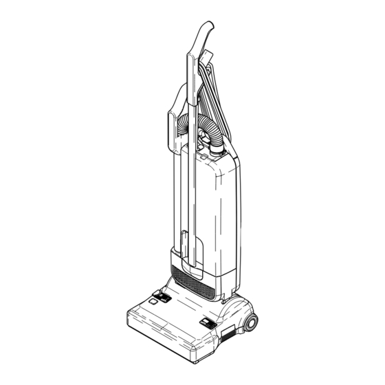
Operations Technical Specifications Item Description Vacuum Motor 1000 Watt Suction 225 mbar [2300mm WS] Air Flow 106 cfm/50 l/s Filter Bag 1.4 gallon/5.3 liter, 3 layer Working Width: 12” Sensor2 11.8 inches/300mm 14” Sensor2 14.2 inches/360mm Brush Strip Replaceable Brush Drive Non-slip drive belt Cable 12”... - Page 11 Operations Control/Components 1. Handle grip 11. Pile adjustment knob 2. Handle tube 12. Release button 3. Retaining ring 13. Mains cable 4. Bag full indicator 14. Rear carrying handle 5. Attachment tube handle 15. Cover release latch 6. Hose 16. Cable hook 7.
-
Page 12: Assembling The Vacuum Cleaner
Operations Assembling the Vacuum Cleaner Carefully place the dust bag housing (20) in the vertical position. Fit it over the swivel neck (21) and support lever (46) of the power head (9) until the release button (12) locks. To dismantle, press the release button (12) and remove the dust bag housing (20) from the power head (9). - Page 13 Operations Finally insert the mains cable into the cable cleat (23). You can hear a “click” when the mains cable is fully inserted. To take off the mains cable push the button (34) next to the cable cleat (23) and remove the mains cable.
-
Page 14: Operating Instructions
Operations Operating Instructions The Sensor2 vacuum cleaners are designed for high performance, usability and durability. The rotating brush with manual height adjustment cleans your carpets and other floors safely and thoroughly. The hose and attachment tube allow all around cleaning. The machine features S-Class filter technology to meet modern hygiene requirements. - Page 15 Operations This vacuum cleaner has a brush jammed indicator (27). If the brush is jammed or overloaded the machine will automatically switch-off and the orange indicator shows in the display (36). If this occurs, unplug the machine and clear the obstruction. ALWAYS unplug from the mains socket before dismantling any part of the machine.
-
Page 16: Maintenance
Maintenance Maintenance and Service ALWAYS unplug from the mains socket before dismantling any part of the machine. Bag Full Indicator If the warning indicator (4) turns orange, it indicates that there is a reduced air flow. This is caused either by dirty filters, a blockage in the hose or base of the machine, or a full paper bag. -
Page 17: Changing The Brush Strip
Operations The Exhaust Filter (39) is located inside the separate Filter holder (40). To change the Exhaust Filter (39) pull out the Exhaust Filter holder (40). The internal filter can be easily taken out. Replace the Exhaust Filter (39) with the sealing gasket (41) downwards and insert the filter holder back into the dust bag housing. -
Page 18: Clearing Blockages
Operations Clearing Blockages Blockages in the hose can cleared by taking the hose off the machine. Squeeze the retaining ring (3) and remove hose. If there is no visible blockage, place wrong end of hose in connecting tube (24), hold it upright with one hand, block the top with other hand and switch machine on. - Page 19 Parts PARTS 86400000 - Sensor2...
-
Page 20: Upper Housing
Upper Housing 16 17 30 A-B 86400000 - Sensor2... - Page 21 Upper Housing PART NO. PRV. NO. DESCRIPTION NOTES 86394300 50100WI DUST BAG HOUSING KPL 86394460 50145WI HANDLE TUBE INCL. TUBE COVER 86144830 0127ER SCREW, M4 X 10 86394470 50147ER CLAMP 86394480 50153SWER HANDLE CPL. 86397550 0104ER SCREW 3.9 X 25 86394320 50200BG DUSTBAG HOUSING...
-
Page 22: 12" Power Head
12” Power Head 86400000 - Sensor2... - Page 23 12” Power Head PART NO. PRV. NO. DESCRIPTION NOTES 86397640 50401BGWI POWER HEAD COVER WINDSOR S2-12 86397260 1013WI SUPPRESSOR KIT 86397570 50414WI CHASSIS 12" 86397580 50313sw BUMPER 86397390 05112WI SWITCH 86397480 50443UL SWITCHING UNIT 86397470 50308WI COVER FOR AIR CHANNEL 86140010 2856 CLAMP...
-
Page 24: 14" Power Head
14” Power Head 86400000 - Sensor2... - Page 25 14” Power Head PART NO. PRV. NO. DESCRIPTION NOTES 86397710 50431BGWI POWER HEAD COVER WINDSOR S2-15 86397260 1013WI SUPPRESSOR KIT 86397660 50444WI CHASSIS 14" 86397670 50314sw BUMPER 86397390 05112WI SWITCH 86397480 50443UL SWITCHING UNIT 86397470 50308WI COVER FOR AIR CHANNEL 86140010 2856 CLAMP...
-
Page 26: Wiring Diagram
Wiring Diagram 86400000 - Sensor2... - Page 27 Notes 86400000 - Sensor2...
- Page 28 86400000-E 06918...
Need help?
Do you have a question about the WINDSOR 12" Sensor2 and is the answer not in the manual?
Questions and answers