Table of Contents
Advertisement
Advertisement
Table of Contents

Related Manuals for Klutch MIG 140i


Summary of Contents for Klutch MIG 140i
- Page 1 MIG 140i 120V Inverter MIG Welder Owner’s Manual WARNING: Read carefully and understand all ASSEMBLY AND OPERATION INSTRUCTIONS before operating. Failure to follow the safety rules and other basic safety precautions may result in serious personal injury. Item #74220 READ & SAVE THESE INSTRUCTIONS...
- Page 2 ® Thank you very much for choosing a Klutch product! For future reference, please complete the owner’s record below: Serial Number/Lot Date Code: ________________________________ Purchase Date: ____________________________________________ Save the receipt, warranty, and this manual. It is important that you read the entire manual to become familiar with this product before you begin using it.
-
Page 3: Table Of Contents
Table of Contents Intended Use ............................4 Packaging Contents ..........................4 Technical Specifications ........................4 Important Safety Information ....................... 5 Specific Operation Warnings ....................... 6 Main Parts of MIG140i ......................... 11 Setting Up Equipment ......................... 12 Before Each Use ..........................18 Operating Instructions ........................ -
Page 4: Intended Use
Intended Use The Klutch MIG 140i is an inverter-powered, wire feed welder for flux core and MIG welding. It comes complete with a regulator and gas hose for easy connection for MIG. Directly connect this unit to a 120V household power. It is designed to weld materials as thin as 24 gauge all the way up to 3/16" in a single pass. -
Page 5: Important Safety Information
Important Safety Information ⚠WARNING • Read and understand all instructions. Failure to follow all instructions may result in serious injury or property damage. • The warnings, cautions, and instructions in this manual cannot cover all possible conditions or situations that could occur. Exercise common sense and caution when using this tool. Always be aware of the environment and ensure that the tool is used in a safe and responsible manner. -
Page 6: Specific Operation Warnings
⚠WARNING PERSONAL SAFETY • Stay alert, watch what you are doing, and use common sense when operating the tool. Do not use the tool while you are tired or under the influence of drugs, alcohol, or medication. A moment of inattention while operating the tool may result in serious personal injury. - Page 7 • Always have a qualified person install and operate this equipment. • Make sure the area is clean, dry, and ventilated. Do not operate the welder in humid, wet, or poorly ventilated areas. • Always have your welder maintained by a qualified technician in accordance with local, state and national codes.
- Page 8 • Keep hands and fingers away from moving parts. • Do not point the torch at a body part of yours or anyone else’s. • Always use this welder in the rated duty cycle to prevent excessive heat and failure. ⚠WARNING Electrical Shock Electric arc welders can produce a shock that can cause injury or death.
- Page 9 safety data sheet for the manufacturer’s instructions. • Do not weld near materials that will emit toxic fumes when heated. Vapors from cleaners, sprays, and degreasers can be highly toxic when heated. ⚠WARNING UV and IR Arc Rays The welding arc produces ultraviolet (UV) and infrared (IR) rays that can cause injury to your eyes and skin.
- Page 10 • To prevent any unintended arcs, cut the wire back to ¼" stick out after welding. ⚠CAUTION Hot Materials - Welded materials are hot and can cause severe burns if handled improperly. • Do not touch welded materials with bare hands. •...
-
Page 11: Main Parts Of Mig140I
• Be sure this welding machine is grounded. • If interference still occurs, the user must take extra measures such as moving the welding machine, using shielded cables, using line filters, or shielding the work area. ⚠WARNING Shielding Gas Cylinders Can Explode High pressure cylinders can explode if damaged;... -
Page 12: Setting Up Equipment
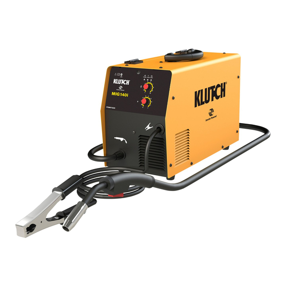
Figure 1 Reference Subassembly MIG 140i MIG Torch Ground Cable & Clamp Setting Up Equipment ⚠WARNING ELECTRIC SHOCK CAN KILL! • High voltage danger from power source! Consult a qualified electrician for proper installation of receptacle. This welder must be grounded while in use to protect the operator from electrical shock. - Page 13 4. INSTALL THE WIRE a. Select welding wire - We recommend the use of .030 Wire on this unit. However, .023 - .035 wire may be used. Both four-inch and eight-inch wire spools can be used on this welder. Figure 2 NOTE: - Metal thinner than 24-gauge cannot be welded with this machine.
- Page 14 Contact Flux Core Nozzle Nozzle Figure 3 iv. Place the spool on the spool hub so the wire will pull off the bottom of the spool. The welding wire should always come off the bottom of the spool into the drive mechanism (Figure 4).
- Page 15 vi. Setting the wire spool tension. a) Turn the spool of wire with one hand. b) Increase the spool tension by tightening (turn clockwise) the wing nut while turning the spool. Turn the spool while tightening the wing nut until the spool slows down and you feel a slight drag.
- Page 16 xx. Select a contact tip stamped with the same diameter as the wire being used. NOTE: Due to inherent variances in flux core welding wire, it may be necessary to use a contact tip one size larger than your flux core wire, if wire jams occur. xxi.
- Page 17 a. Connect one end of the gas hose to the gas hose connection on the back of the welder. b. Connect the other end of the gas hose to the gas hose connection on the supplied regulator/flow gauge. c. Before installing the regulator, it is good practice to make certain there is not debris in the gas bottle connection.
-
Page 18: Before Each Use
6.7 GAS SELECTION Different materials require different shielding gas when MIG welding, refer to the set-up chart inside the wire feed compartment. Mild Steel: Use 75% Argon and 25% CO2 for reduced spatter and reduced penetration for thinner materials. Do NOT USE Argon gas concentrations higher than 75% on steel. The result will be poor penetration, porosity, and brittleness of weld. -
Page 19: Operating Instructions
Operating Instructions ⚠WARNING High voltage danger from power source! • Consult a qualified electrician for proper installation of receptacle at the power source. This welder must be grounded while in use to protect the operator from electrical shock. If you are not sure if your outlet is properly grounded, have it checked by a qualified electrician. - Page 20 ⚠WARNING EXPOSURE TO A WELDING ARC IS EXTREMELY HARMFUL TO THE EYES AND SKIN! • Prolonged exposure to the welding arc can cause blindness and burns. Never strike an arc or begin welding until you are adequately protected. Wear flame-proof welding gloves, a heavy long-sleeved shirt, trousers without cuffs, high topped shoes, and an ANSI approved welding helmet.
- Page 21 Travel direction is the direction the torch is moved along the weld joint in relation to the weld puddle. The torch is either PUSHED into the weld puddle or PULLED away from the weld puddle. For most welding jobs you will pull the torch along the weld joint to take advantage of the greater weld puddle visibility.
- Page 22 c. Welding Positions The FLAT POSITION is the easiest of the welding positions and is most commonly used. It is best if you can weld in the flat position, if possible, as good results are easier to achieve in this position. The HORIZONTAL POSITION is performed very much the same as the flat weld except that angle B (see HOLDING THE TORCH) is such that the wire, directed more toward the metal above the weld joint, is to help prevent the weld puddle from running downward while...
- Page 23 d. Multiple Pass Welding Butt Weld Joints When butt welding thicker materials; you will need to prepare the edges of the material to be joined by grinding a bevel on the edge of one or both pieces of the metal being joined. When this is done, a “V” is created between the two pieces of metal that will have to be welded closed.
- Page 24 e. Spot Welding There are three methods of spot welding: Burn-Through, Punch and Fill, and Lap. Each has advantages and disadvantages, depending on the specific application as well as personal preference. i. The BURN-THROUGH METHOD welds two overlapped pieces of metal together by burning through the top piece and into the bottom piece.
-
Page 25: After Each Use
5. SPOT WELDING INSTRUCTIONS a. Select the wire diameter and heat setting recommended above for the method of spot welding you intend to use. b. Tune in the wire speed as if you were creating a continuous weld. c. Hold the nozzle piece completely perpendicular to and about 1/4 inch off the work piece. d. -
Page 26: Troubleshooting
• Disconnect input power before installing, maintaining or servicing this equipment. Lockout/tag out input power according to OSHA 29 CFR 1910.147. Maintain the welder by adopting a program of conscientious repair and maintenance in accordance with the following recommended procedures. It is recommended that the general condition of any tool be examined before it is used. - Page 27 Failure Possible Cause Corrective Action Unit is not plugged in. Plug in unit. Unit does not power up. Input power circuit breaker not on. Reset input power circuit breaker. The main power switch is not working. Replace main power switch. Leave power on and let the fan cool the The internal temperature is too high.
-
Page 28: Parts Diagram
Failure Possible Cause Corrective Action MIG torch is not correctly installed and Remove and reconnect the MIG torch shielding gas is not transferring to the to make certain it is completely installed arc. into the MIG connector. Refer to the label inside the wire Wire speed setting is incorrect. -
Page 29: Replacement Parts
GAS CONNECTOR 105400050 POWER SWITCH 105200080 DOOR LATCH 125200073 DOOR 125200075 OPERATORS MANUAL MIG 140i 105200081 GAS HOSE TO REGULATOR 105200082 INERT GAS REGULATOR ** Item not shown. Replacement Parts • For replacement parts and technical questions, please call Customer Service at 1-800-222-5381. -
Page 30: Limited Warranty
Northern Tool and Equipment Company, Inc. ("We'' or "Us'') warrants to the original purchaser only ("You'' or "Your") that the Klutch product purchased will be free from material defects in both materials and workmanship, normal wear and tear excepted, for a period of three years from date of purchase. The foregoing warranty is valid only if the installation and use of the product is strictly in accordance with product instructions. - Page 31 Distributed by: Northern Tool & Equipment Company, Inc. Burnsville, Minnesota 55306 www.northerntool.com Made in China Page 31 of 31...
Need help?
Do you have a question about the MIG 140i and is the answer not in the manual?
Questions and answers