Table of Contents
Advertisement
Quick Links
Advertisement
Table of Contents

Related Manuals for Klutch MP 120/230V Welder 180A


Summary of Contents for Klutch MP 120/230V Welder 180A
- Page 1 MP 120/230V Welder 180A WARNING: Read carefully and understand all ASSEMBLY AND OPERATION INSTRUCTIONS before operating. Failure to follow the safety rules and other basic safety precautions may result in serious personal injury. Item #5875885 READ & SAVE THESE INSTRUCTIONS...
-
Page 2: Table Of Contents
Table of Contents ......................2 GENERAL SAFETY INSTRUCTION Description ............................6 Check the contents with the packing list below................6 .........................7 Specifications and Dimension Know your Welder ..........................8 .............................. 9 Installtion .............................12 Operation ........................18 SPOOL GUN ASSEMBLY .........................19 Trouble shooting Chart ..........................21 Main Circuit chart ............................22... -
Page 3: General Safety Instruction
Operating Instructions and Parts Manual Please read and save these instructions. Read through this owner’s manual carefully before using product. Protect yourself and others by observing all safety information, warnings, and cautions. Failure to comply with instructions could result in personal injury and/or damage to product or property. - Page 4 standard) and safety glasses while welding. -Wear proper gloves and protective clothing to prevent your skin from being exposed to hot metals, UV and IR rays. -Do not overuse or overheat your welder. Allow proper cooling time between duty cycles. -Keep hands and fingers away from moving parts and stay away from the drive rolls.
- Page 5 UV and IR Arc Rays The welding arc produces ultraviolet (UV) and infrared (IR) rays that can cause injury to your eyes and skin. Do not look at the welding arc without proper eye protection. -Always use a helmet that covers your full face from the neck to top of head and to the back of each ear.
- Page 6 Welding creates hot sparks that can cause injury. Chipping slag off welds creates flying debris. -Wear protective apparel at all times: ANSI-approved safety glasses or shield, welder’s hat and ear plugs to keep sparks out of ears and hair. Electromagnetic Field -Electromagnetic fields can interfere with various electrical and electronic devices such as pacemakers.
-
Page 7: Description
A 15 amp time delay fuse or circuit breaker is recommended. 1 0A MIG/Flux Welder series is ideal for Do-It-Yourself projects or for light maintenance.MIG weld carbon steel, stainless steel . MP 120/230V Welder 180A is Spool Gun Ready. Check the contents with the packing list below. -
Page 8: Specifications And Dimension
Specifications and Dimension Description Specification Model Welder Input power 120/2 0 Frequency 50/60 Open Circuit Voltage 22 A @ 120V Current Input 28 A @ 230V Welding Current Range 120V: 30 -140A 230V: 30-180A 120V: 40% @ 90A 230V: 25% @ 160A Rated Duty Cycle 60% @ 73A 60% @ 103A... -
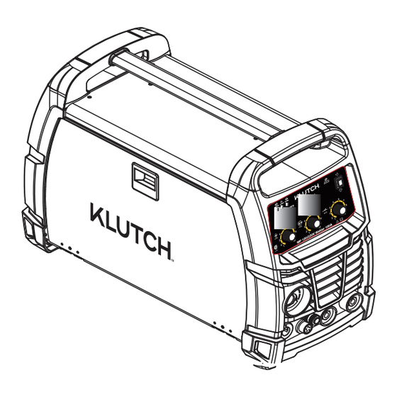
Page 9: Know Your Welder
Know your Welder POWER INDICATOR When the machine is turned on, the power indicator will be on. ALARM INDICATOR When the thermal indictor is on, it shows the machine is overloaded and the internal temperature is too high. Weld output will turn off automatically but the fan will still be working. -
Page 10: Power Cord
POWER CORD The power cord connects the welder to the 120 volt power supply. 15amp receptacle to supply power to the welder. WELDING CABLE The welding cable are attached to electrode to complete the circuit, allowing the flow of current needed to weld. CABLE The ground cable/clamp are attached to the work piece to complete the circuit, allowing the flow of current needed to weld. - Page 11 welding is generally easier, faster, and allows for better penetration. If possible, the work piece should be positioned so that the bead will run on a flat surface. 3.2 Preparing the Joint Before welding, the surface of work piece needs to be free of dirt, rust, scale, oil or paint.
-
Page 12: Gas Installation
5. Sett ing the wire tension Arc flash can injure eyes! To reduce the risk of arc flash, make certain that the wire coming out of the end of the torch does not come in contact with work piece, ground clamp or any grounded material during the drive tension setting process or arcing will occur. -
Page 13: Operation
Cylinder valve: Controls GAS CYLINDER gas flow. Cylinder pressure gauge Gas flow gauge, set at 20 CFH Regulator Adjustment knob controls gas pressure to the welder. Gas hose Gas cylinder NOTE: Slowly open the cylinder valve by turning it counterclockwise until the cylinder pressure gauge registers on the first gauge of the regulator. - Page 14 1. Main control component Power switch - The power switch supplies electrical current to the welder. Whenever the power switch is in the ON position, the welding circuit is activated. ALWAYS turn the power switch to the OFF position and unplug the welder before performing any maintenance.
-
Page 15: Welding Techniques
5. Tuning in the wire speed This is one of the most important parts of MIG welder operation and must be done before starting each welding job or whenever any of the following variables are changed: heat setting, wire diameter, or wire type. EXPOSURE TO A WELDING ARC IS EXTREMELY HARMFUL TO THE EYES AND SKIN! Prolonged exposure to the welding arc can cause blindness and burns. - Page 16 Torch travel refers to the movement of the torch along the weld joint and is broken into two elements: Direction and Speed. A solid weld bead requires that the welding torch be moved steadily and at the right speed along the weld joint. Moving the torch too fast, too slow, or erratically will prevent proper fusion or create a lumpy, uneven bead.
- Page 17 6.3 Welding position FLAT POSITION Is easiest of the welding positions and is most commonly used. It is best if you can weld in the flat position if at all possible as good results are easier to achieve. HORIZONTAL POSITION Is performed very much the same as the flat weld except that angle B (see HOLDING THE TORCH) is such that the wire, Directed more toward the metal above the weld joint is to help prevent the weld puddle from running downward while still allowing slow enough travel speed .A good starting point for...
- Page 18 6.4 Multiple pass welding Butt Weld Joints When butt welding thicker materials you will need to prepare the edges of the material to be joined by grinding a bevel on the edge of one or both pieces of the metal being joined. When this is done, a “V” is created between the two pieces of metal that will have to be welded closed.
-
Page 19: Spool Gun Assembly
SPOOL GUN ASSENBLY This unit is set-up to accept the Quick Draw Spool gun only the Quick Draw Spool gun has three connection points at the back of the spool gun(Figure 9) 1) The gas connection is a slide-on quick connector. 2) The weld power connection has a round ring connection. -
Page 20: Trouble Shooting Chart
Trouble shooting Chart Breakdown Analysis Solutions Voltage is too Switch off power source; Check the main supply; Restart welder when power recovers to normal Voltage is too low state. Bad power Improve the ventilation condition. Yellow ventilation lead to Indicator is over-heat protection Circumstance... - Page 21 Too large contact Change the proper contact tip or tip makes the roller current unsteady Too thin power Change the power cable cable makes the Arc is not stable and power astaticism splash is large Too low input Enhance the input voltage voltage Wire feeding Clean or replace the liner and the...
-
Page 22: Main Circuit Chart
Main Circuit chart... -
Page 23: Spare Part List
Spare Part List... -
Page 24: Repair Parts List
Repair Parts List CODE DESCRIPTION 125300108 125300109 125300110 125300111 125300112 125300113 125300114 125300115 c i t 125300116 125300117 125300118 125300119 125300120 y t i 125300121 125300122 125300123 125200093 Spool Gun Gas Connector 125300123 125300137 125300125 125300126 Wire Feeder Support 125300127 125300128 125300129 125300131... -
Page 25: Service Maintenance, Transportation And Storage
Service Maintenance, Transportation and Storage The welder needs regular maintenance as following: Periodically clean dust, dirt, grease, etc. from your welder. Every six months, or as necessary, remove the cover panel from the welder and air-blow any dust and dirt that may have accumulated inside the welder. Replace power cord, ground cable, ground clamp, or electrode assembly when damaged or worn. - Page 26 Distributed by: Northern Tool & Equipment Company, Inc. Burnsville, Minnesota 55306 www.northerntool.com Made in China...
Need help?
Do you have a question about the MP 120/230V Welder 180A and is the answer not in the manual?
Questions and answers