Table of Contents
Advertisement
Advertisement
Table of Contents

Related Manuals for Klutch MIG 180SG


Summary of Contents for Klutch MIG 180SG
- Page 1 MIG 180SG Spoolgun Welder with Cart Owner’s Manual WARNING: Read carefully and understand all ASSEMBLY AND OPERATION INSTRUCTIONS before operating. Failure to follow the safety rules and other basic safety precautions may result in serious personal injury. Item #55729 SAVE THESE INSTRUCTIONS...
- Page 2 ® Thank you very much for choosing a Klutch product! For future reference, please complete the owner’s record below: Serial Number/Lot Date Code: ________________________________ Purchase Date: ____________________________________________ Save the receipt, warranty, and this manual. It is important that you read the entire manual to become familiar with this product before you begin using it.
-
Page 3: Table Of Contents
Table of Contents Intended Use ............................4 Important Safety Information ....................... 5 General Safety Rules ..........................6 Specifications of Welder ........................10 Main Parts of Welder ........................... 11 Setting Up Equipment ......................... 12 Operating Instructions ........................18 Maintenance ............................24 Troubleshooting .......................... -
Page 4: Intended Use
Intended Use The Klutch MIG180SG is an inverter-powered, 230V welder with spool gun designed for MIG welding aluminum and other MIG and flux cored wires. The wire feed system is the spoolgun and can accommodate a variety of welding wires that are available on 4 inch spools. It comes complete with a regulator and gas hose for easy connection for MIG welding. -
Page 5: Important Safety Information
Important Safety Information ⚠WARNING Read and understand all instructions. Failure to follow all instructions may result in serious injury or property damage. The warnings, cautions, and instructions in this manual cannot cover all possible conditions or situations that could occur. Exercise common sense and caution when using this tool. Always be aware of the environment and ensure that the tool is used in a safe and responsible manner. -
Page 6: General Safety Rules
parts. Air vents on the tool often cover moving parts and should be avoided. Wear the proper personal protective equipment when necessary. Use ANSI Z87.1 compliant safety goggles (not safety glasses) with side shields, or when needed, a face shield. Use a dust mask in dusty work conditions. - Page 7 ⚠WARNING Your Welding Environment Keep the environment you will be welding in free from flammable materials. Always keep a fire extinguisher accessible to your welding environment. Always have a qualified person install and operate this equipment. Make sure the area is clean, dry, and ventilated.
- Page 8 ⚠WARNING Electrical Shock Electric arc welders can produce a shock that can cause injury or death. Touching electrically live parts can cause fatal shocks and severe burns. While welding, all metal components connected to the wire are electrically hot. Poor ground connections are a hazard, so secure the ground lead before welding.
- Page 9 Warn people in your welding area when you are going to strike an arc so they can protect themselves. ⚠WARNING Fire Hazards Do not weld on containers or pipes that contain or have had flammable, gaseous, or liquid combustibles in them. Welding creates sparks and heat that can ignite flammable and explosive materials.
-
Page 10: Specifications Of Welder
Never expose cylinders to high heat, sparks, open flames, mechanical shocks, or arcs. Do not touch the cylinder with the MIG gun. Do not weld on the cylinder Always secure the cylinder upright to a cart or stationary object. ... -
Page 11: Main Parts Of Welder
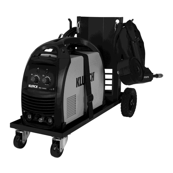
Main Parts of Welder Figure 1. Page 11 of 33... -
Page 12: Setting Up Equipment
Reference Subassembly Spool Gun Positive (+) Weld Output Connection Output Voltage Control Power On Indicator Light Alarm Indicator Light Securement Strap MIG Cart Wire Feed Speed Control Negative (-) Weld Output Connection Inert Gas Regulator and Gas Hose Ground Cable and Clamp Contact Tips Setting Up Equipment ⚠WARNING... - Page 13 Figure 2. Positive (+) Negative (-) Trigger Control Gas Connection Weld Receptacle Weld Receptacle Receptacle Receptacle Figure 3. 4. CONNECT THE SPOOL GUN a. Connect the Gas Connector on the Spool Gun to the Gas Connection Receptacle on the lower front panel of the welding unit. See Figure 3. Page 13 of 33...
- Page 14 b. Connect the weld cable twist lock connector on the Spool Gun to the positive (+) Weld Receptacle on the lower front panel of the welding unit. See Figure 3. NOTE: When welding with flux cored wire on steel, the weld cable twist lock connector on the spool gun should be connected to the negative (-) Weld Receptacle on the lower front panel of the welding unit to run DCEN (DC Electrode Negative).
- Page 15 ⚠WARNING ELECTRIC SHOCK CAN KILL! High voltage danger from power source! Consult a qualified electrician for proper installation of receptacle. This welder must be grounded while in use to protect the operator from electrical shock. Do not remove grounding prong or alter the plug in any way. Use only the supplied adapter between the welder's power cord and the power source receptacle.
- Page 16 ⚠CAUTION CHECK WIRE PATH Make certain that the welding wire is actually going into the torch liner. If not, the wire can jam or keep the wire from feeding correctly. m. Check to see if the wire is in the drive roller groove, then release the tension arm into place on the drive roller.
- Page 17 Always secure the cylinder upright to a cart or stationary object. Keep cylinders away from welding or electrical circuits. Use the proper regulators, gas hose, and fittings for the specific application. a. Polarity Changing - When MIG wire is used, shielding gas is required and the polarity on this unit needs to be electrode positive.
-
Page 18: Operating Instructions
any debris in the connection. Connect the regulator to the gas bottle connection. Use a wrench to snug up the connection. vi. Open the Gas Bottle Valve on the cylinder of gas. vii. Turn the Gas Flow Adjuster on the regulator so that the gas flow rate is set at approximately 20 CFM. - Page 19 NOTE: The wire will feed faster without an arc. When an arc is being drawn, the wire speed will slow down. 4. HOLDING THE TORCH - The best way to hold the welding torch is the way it feels most comfortable to you.
- Page 20 6. WELDING TECHNIQUES ⚠WARNING EXPOSURE TO A WELDING ARC IS EXTREMELY HARMFUL TO THE EYES AND SKIN! Prolonged exposure to the welding arc can cause blindness and burns. Never strike an arc or begin welding until you are adequately protected. Wear flame-proof welding gloves, a heavy long sleeved shirt, trousers without cuffs, high topped shoes, and an ANSI approved welding helmet.
- Page 21 keeping the wire and nozzle centered over the weld joint. Refer to the following illustration: The WEAVE BEAD is used when you want to deposit metal over a wider space than would be possible with a stringer bead. It’s made by weaving from side to side while moving with the torch.
- Page 22 OVERHEAD POSITION - is the most difficult welding position. Angle A (see HOLDING THE TORCH) should be maintained at 60 degrees. Maintaining this angle will reduce the chances of molten metal falling into the nozzle. Angle B should be held at zero degrees so that the wire is aiming directly into the weld joint.
- Page 23 NOTE: WHEN USING SELF-SHIELDING FLUX-CORE WIRE it is very important to thoroughly chip and brush the slag off each completed weld bead before making another pass or the next pass will be of poor quality. Fillet Weld Joints. Most fillet weld joints, on metals of moderate to heavy thickness, will require multiple pass welds to produce a strong joint.
-
Page 24: Maintenance
i. The BURN-THROUGH METHOD welds two overlapped pieces of metal together by burning through the top piece and into the bottom piece. With the burn-through method, larger wire diameters tend to work better than smaller diameters. Wire diameters that tend to work best, with the burn-through method are 0.035 inch self-shielding flux-core wire. -
Page 25: Troubleshooting
Maintenance Interval Maintenance Point Inspect all cords and power cables. Replace any cords or Before Each Use power cables that are damaged or cracked. Inspect all warning and caution labels attached to this unit. If Every 3 Months they are worn, torn or otherwise unreadable, replace them. Inspect, clean, and tighten all weld power connections. - Page 26 Failure Possible Cause Corrective Action Wire Will Feed Only When Trigger Is Trigger Is Not Mashed. Mashed. Spool Gun Motor Is Damaged. Replace Spool Gun. Feed Roller Is Not Correctly See Installation Section to Correctly Installed. Install Drive Roller. Wire Feeds Torch Liner is plugged.
-
Page 27: Parts Diagram Welder
Parts Diagram Welder Page 27 of 33... -
Page 28: Parts List Welder
FRONT PANEL BOARD 125200019 NAMEPLATE MIG 180SG 105200223 VOLTAGE POTENTIOMETER 105200224 WIRE FEED POTENTIOMETER 105200215 PLASTIC BEZEL 105200224 WELD OUTPUT SUPPORT BOARD 105200225 MAIN CONTROL PC BOARD 105200226 CONTROL BOARD SUPPORT 105200227 SPOOLGUN 125200020 OPERATOR'S MANUAL MIG 180SG Page 28 of 33... -
Page 29: Parts Diagram Spoolgun
Parts Diagram Spoolgun Parts List Spoolgun Reference Part Number Item Description Quantity 105200062 NOZZLE 105200043 CONTACT TIP 105200088 SPOOL GUN 105200089 TWIST LOCK CONNECTOR 10-25 105200092 DRIVE ROLL 105200093 DRIVE ROLL PRESSURE ARM 105200094 INLET GUIDE 105200095 IDLE ROLL 105200096 LINER 105200097 BARREL... -
Page 30: Parts Diagram Of Cart
Parts Diagram of Cart Page 30 of 33... -
Page 31: Parts List Of Cart
Parts List of Cart Reference Part Number Item Description Quantity 105100137 STRAP KLUTCH MIG 180SG 105100138 GAS CYLINDER SUPPORT 105100139 CABLE HANDER 105100140 MOUNTING BRACKETS 105100037 AXLE BRACKETS 105100141 BOTTOM 105100142 AXLE 105100041 CASTER 105100003 WHEEL Replacement Parts For replacement parts and technical questions, please call Customer Service at 1-800-222-5381. -
Page 32: Limited Warranty
Northern Tool and Equipment Company, Inc. ("We'' or "Us'') warrants to the original purchaser only ("You'' or ''Your'') that the Klutch product purchased will be free from material defects in both materials and workmanship, normal wear and tear excepted, for a period of three years from date of purchase. - Page 33 Distributed by: Northern Tool & Equipment Company, Inc. Burnsville, Minnesota 55306 www.northerntool.com Made in China Page 33 of 33...
Need help?
Do you have a question about the MIG 180SG and is the answer not in the manual?
Questions and answers