
Related Manuals for Pego VISION SC600


Summary of Contents for Pego VISION SC600
- Page 1 VISION SC600 Use and maintenance manual ENGLISH READ AND KEEP Rel. Software: 8 REV. 02-18 ELECTRICAL BOARDS FOR REFRIGERATING INSTALLATIONS...
- Page 2 VISION SC600 USE AND MAINTENANCE MANUAL Pag. 2 Rev. 02-18...
-
Page 3: Table Of Contents
Main warnings for the installer Pag. 6 Standard equipment for assembly and use Pag. 7 Board installation FUNCTIONALITY CHAP. 3 Pag. 8 Functions managed by VISION SC600 TECHNICAL FEATURES CHAP. 4 Pag. 9 4.1. Technical features Pag. 10 Warranty conditions DATA PROGRAMMING CHAP. -
Page 4: Generality
CHAPTER 1: INTRODUCTION GENERALITY The VISION SC600 system allows users to control the machine room of a refrigeration plant in which there is more than one compressor. It guarantees uniform operation and proper distribution of operating times among individual machines. All functions are performed in complete safety and the VISION SC600 Control Console (LCD DISPLAY) can be installed anywhere, independently of where the power cabinet is located. -
Page 5: Pag.
CAP. 1 - Introduction VISION SC600 PRODUCT IDENTIFICATION CODES VISION SC600 Compressor and condenser fan control of a refrigeration plant. OVERALL CLEARANCES Dimensions in mm: VISION SC600 100N MASTER3 SC600 IDENTIFICATION DATA The equipment described in this manual is provided with an identification data plate of the same placed on one side: •... -
Page 6: Main Warnings For The Installer
. The extending or shortening of the probes may alter the factory calibration; use an external thermometer to check and calibrate. STANDARD EQUIPMENT FOR ASSEMBLY AND USE For assembly and use, the electronic controller VISION SC600, is equipped with: • Nr 1 telephone plug cable; • Nr 1 use manual;... - Page 7 Fig. 1: Position the module 100N MASTER3 on the DIN guide and close the 2 lower hooks to lock it on the same. Fig. 2: Fix the VISION SC600 console using the two screws to be inserted in the slots underneath the keys frame.
- Page 8 CAP. 3 - Functionality VISION SC600 CHAPTER 3: FUNCTIONALITY FUNCTIONS MANAGED BY VISION SC600 Compressor control of a refrigeration plant, up to a maximum of 10. Condenser fan control of a refrigeration plant, up to a maximum of 10. It’s possible to configure the outputs by setting the number of compressors and fans to control, so that their sum is less than or equal to 10.
-
Page 9: Technical Features
CAP. 4 - Technical features VISION SC600 CHAPTER 4: TECHNICAL FEATURES TECHNICAL FEATURES Power supply Voltage 230 V~ 10% 50/60Hz Max. absorbed power (electronic control only) ~ 8 VA Climatic Conditions Work temperature -5 ÷ +50 °C Storage temperature -10 ÷... - Page 10 The intervention service in warranty can be refused when the equipment is modified or transformed. Under no circumstances Pego S.r.l. will be liable for any loss of data and information, costs of goods or substitute services, damage to property, people or animals, loss of sales...
-
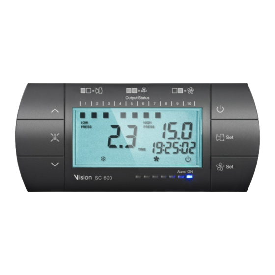
Page 11: Control Panel
CHAP. 5 - Data programming VISION SC600 CHAPTER 5: DATA PROGRAMMING CONTROL PANEL State led FRONT KEYBOARD FANS SET Allows you to set the fans set point when pressed in combination with the Up or Down button. Reset the alarm sound if any. - Page 12 CHAP. 5 - Data programming VISION SC600 MUTE ALARM Reset sound alarm if any. If pressed more than 3 seconds displays the alarm history. Increases the values / Scroll up the parameters KEYS COMBINATIONS EXIT PROGRAMMING If pressed simultaneously for more than 3 seconds within any programming menu or the historical alarm allow you to exit the menu.
- Page 13 CHAP. 5 - Data programming VISION SC600 SWITCHING FROM Bar to °C While viewing several variables in Bar, pressing the stand-by key and Set together switches the view from Bar to °C according to the table of the gas type selected until the keys are released.
- Page 14 Off = delivery sensor reading (high pressure) in °C. PRESS GENERALITY For the operator’s safety and practicality, VISION SC600 system envisions three programming levels; the first for configuration of the frequently amendable SET POINT parameters only, the second for programming and setting the main parameters relating to the various board functioning modes, and the third for programming input/output of the board.
- Page 15 CHAP. 5 - Data programming VISION SC600 SYMBOLS For practicality we will use the following symbols: • () the UP key that performs value increase functions; • () the DOWN key that performs value decrease functions. SET POINT SETTING AND DISPLAYING 1.
- Page 16 CHAP. 5 - Data programming VISION SC600 FIRST LEVEL VARIABLES LIST (User Level) LABEL MEANING VALUES DEFAULT 0.2 30 bar SET differential (of the pressure) compressors (interlocked with nC) Step 0.2 Bar The minimum time that must elapse between the insertion of a compressor 2 ...
- Page 17 CHAP. 5 - Data programming VISION SC600 View of the last alarm triggered Alarm code Read only Minimum compressor pressure alarm The absolute pressure referring to the Intake probe below which, once the Ald delay time is activated, the LOW pressure alarm is triggered showing ELc alternating -0,6 ÷...
- Page 18 CHAP. 5 - Data programming VISION SC600 LEVEL 2 PROGRAMMING (Installer level) 5.10 In order to access the 2 programming Level, press and hold the UP key (), the DOWN key () and the STAND-BY key for over 3 seconds.
- Page 19 CHAP. 5 - Data programming VISION SC600 Time (min.) with which the freon/oil pre- 0 240 min alarm (Ep) becomes alarm (EF). Once this 30 min time has passed, all outputs are disabled. Offset Inverter fans (of pressure) 0,5 2,5 bar Value always less than (r0V) value always <...
- Page 20 CHAP. 5 - Data programming VISION SC600 Network address for connection to the 0 ÷ 31 (con SEr=0) TeleNET or Modbus supervision system 1 ÷ 247 (con SEr=1) (see chap. 6.1) 0 = TeleNET protocol RS-485 communication protocol 1 = Modbus-RTU protocol...
- Page 21 CHAP. 5 - Data programming VISION SC600 LEVEL 3 PROGRAMMING (Installer level) 5.12 To access Level 3 programming, press and hold the UP key (), DOWN key (), STAND-BY key and SET FANS key for over 3 seconds. When the first programming variable appears: 1.
- Page 22 CHAP. 5 - Data programming VISION SC600 0 999 tens of hours Digital output 1 hour counter (resettable)* Read only 0 999 tens of hours Digital output 2 hour counter (resettable)* Read only 0 999 tens of hours...
- Page 23 CHAP. 5 - Data programming VISION SC600 Setting of digital input n.2 as I1 Setting of digital input n.3 as I1 Setting of digital input n.4 as I1 Setting of digital input n.5 as I1 Setting of digital input n.6 as I1 Setting of digital input n.7...
- Page 24 CHAP. 5 - Data Programming VISION SC600 With SEq=0 the activation/deactivation of the digital outputs is a time-based operation, and in particular: - The output that has the least number of operating hours in times t1C/U, t2C/U, t3C/U and t4C/U, and that is available at that time (therefore not in alarm).
- Page 25 CHAP. 5 – Data Programming VISION SC600 INPUTS AND OUTPUTS CONFIGURATION 5.15 The configuration of the outputs of the 100N MASTER unit can be set via the nC, nU and NPC parameters. Each output can be associated with the relative protection via the I1, I2, …...
- Page 26 CHAP. 5 – Data Programming VISION SC600 OPERATING MODE – INVERTER MANAGEMENT 5.16 The operating mode is selected via the iEn parameter. iEn = 0: inverter management deactivated If iEn = 0 both the fans and the compressors are managed with digital outputs and side- band control.
- Page 27 CHAP. 5 - Data Programming VISION SC600 CONTROL IN THE EVENT OF ALARMS With the presence of alarms (alarm outputs 1…nC or 1…nU alarm inputs enabled), operation is maintained equal but the output relating to the alarm in the sequence and the relative alarm is shown on the display (EC1…ECn or EU1…EUn).
- Page 28 CHAP. 5 - Data Programming VISION SC600 Graph n.1 Example with sEq=1 and nC=3 USE AND MAINTENANCE MANUAL Pag. 28 Rev. 02-18...
- Page 29 CHAP. 5 - Data Programming VISION SC600 Graph n.2 Example with sEq=1, NC=3 and the intervention of the times t1c, t2c, t3c. USE AND MAINTENANCE MANUAL Pag. 29 Rev. 02-18...
- Page 30 CHAP. 5 - Data Programming VISION SC600 Graph n.3 Legend Condens. Fan State Condenser fan state (on / off) Delivery pressure Delivery pressure (Bar) for the activation of condenser fans Fans Set point SET POINT (Bar) set by the operator to enable condenser fans.
- Page 31 CHAP. 5 - Data Programming VISION SC600 iEn = 1: compressor inverter management activated If iEn=1, compressor 1 is managed with the 0-10V output and a side-band control. The compressor 1 digital output is used to enable the inverter, the other digital outputs control the remaining compressors with a side-band control.
- Page 32 CHAP. 5 - Data Programming VISION SC600 Graph n. 4 - Example inverter compressor operation. Seq=1, nC=3 and the intervention of times t1c e t2c USE AND MAINTENANCE MANUAL Pag. 32 Rev. 02-18...
- Page 33 CHAP. 5 - Data programming VISION SC600 iEn = 2: fan inverter management enable With iEn=2 you will have the Condenser fan control with 0-10V analogue output and of sideband-type adjustment. Digital Output “Fan 1” represents "the condenser fans inverter activation";...
- Page 34 CHAP. 5 - Data programming VISION SC600 Graph n.5 Delivery pressure increasing Analog output Delivery pressure (Bar) Fan Out Inverter Enable Delivery pressure (Bar) Output pressure DECREASING (Graph. n.6): With output pressure probe values equal or higher than point (D), you will have a 10V analogue output.
- Page 35 CHAP. 5 - Data programming VISION SC600 Graph n.6 Delivery pressure decreasing Analog output Delivery pressure (Bar) Fan Out Inverter Enable Delivery pressure (Bar) CONTROL IN THE EVENT OF ALARMS With the fan output no.1 alarm input activated, the analogue input will be immediately brought to 0V and the digital output no.1 will be opened after (inverter-enabling is...
- Page 36 CHAP. 5 - Data Programming VISION SC600 OPERATING MODE – COMPRESSORS CAPACITY MANAGEMENT 5.17 ± With the NPC parameter = 1, the operation of the compressors is selected and the digital outputs are controlled on a side-band basis and the CAPACITY CONTROL is set to 50%.
- Page 37 CHAP. 5 - Data programming VISION SC600 deactivation is based on this sequence: PC10, C10, PC9, C9, PC8, C8, PC7, C7, PC6, C6, PC5, C5, PC4, C4, PC3, C3, PC2, C2 ,PC1, C1. The number of compressors enabled depends on the deviation between the value measured by the adjustment pressure sensor (positioned at the intake) and the set intake Set point, as well as the t1C e t2C times.
- Page 38 CHAP. 5 - Data Programming VISION SC600 Graph n.7 direct compressors insertion and capacity USE AND MAINTENANCE MANUAL Pag. 38 Rev. 02-18...
- Page 39 (intake) to the address set in the parameter Ad, while answers with the high pressure probe measurement (delivery) to the address (Ad+1). If the VISION SC600 is questioned as a "tool TWMP", it is therefore not possible to set other instruments at Ad +1.
-
Page 40: Diagnostic
VISION SC600 CHAPTER 7: DIAGNOSTICS DIAGNOSTICS In case of anomalies, the VISION SC600 controller warns the operator using alarm codes shown by the display and an acoustic signal emitted by a buzzer inside the Operational console. When there is an alarm, the... - Page 41 CHAP. 7 - Diagnostics VISION SC600 ALARM CODE TABLE: COD. POSSIBLE CAUSE / DESCRITPION ACTION TO BE TAKEN RESET Plant stops and display flashes “OFF” and Remote stand-by active (digital input) automatic pressure value. EEPROM ALARM Switch the appliance off and back on.
- Page 42 CHAP. 7 - Diagnostics VISION SC600 Protection of one or more condenser fans Check the status of the fan(s). (e.g. Thermal protection or max. pressure Check the absorption of the fan(s). … automatic switch.) Check the status of the "outlet no.# (The output of the relative FAN is alarm"...
- Page 43 VISION SC600 ALARM HISTORY MANAGEMENT The VISION SC600 system can log up to 40 alarm events. To display the codes of the logged alarms, press the ALARM OFF key for at least 3 seconds. Sector 1 of the LCD display (see par. 5.4) will indicate when the alarms occurred, from the most recent (0) to the oldest one (39).
- Page 44 DEL FABBRICANTE: THIS DECLARATION OF CONFORMITY IS ISSUED UNDER THE EXCLUSIVE RESPONSIBILITY OF THE MANUFACTURER: PEGO S.r.l. Via Piacentina 6/b, 45030 Occhiobello (RO) – Italy – DENOMINAZIONE DEL PRODOTTO IN OGGETTO / DENOMINATION OF THE PRODUCT IN OBJECT MOD.: VISION SC600 IL PRODOTTO DI CUI SOPRA E’...
- Page 45 Attachments VISION SC600 100N MASTER3 CONNECTION LAYOUT Power supply DESCRIPTION TERMINAL N – L Power supply 1 – 2 115÷230Vac ±10% 50/60Hz onsumption: 20 VA max. Connect ground to terminal 45 of the console (functional earth). This connection helps to limit the effects of electromagnetic noise on the control system.
- Page 46 Attachments VISION SC600 Relay 16A 240V~ (AC1) 23 – 24 Compr. 9 / Partition 9 / Fan 9 3A 240V~ (AC3) Relay 16A 240V~ (AC1) 25 - 26 Compr. 8 / Partition 8 / Fan 8 3A 240V~ (AC3) Analog/digital inputs...
- Page 47 VISION SC600 USE AND MAINTENANCE MANUAL Pag. 47 Rev. 02-18...
- Page 48 Tel. +39 0425 762906 Fax +39 0425 762905 e.mail: info@pego.it – www.pego.it AFTER-SALES ASSISTANCE CENTRE Tel. +39 0425 762906 e.mail: tecnico@pego.it Distributor: MANUALE D’USO E MANUTENZIONE Pag. 48 Rev. 01-13 PEGO s.r.l. reserves the right to make amendments to this user manual at any moment.
Need help?
Do you have a question about the VISION SC600 and is the answer not in the manual?
Questions and answers
100n masg come e2 rero
The 100N MASTER for the Pego VISION SC600 refers to the control circuit board that manages system operations. If an EEPROM memory error (E0) is detected in the 100N MASTER, the system disables all outputs except shut-down alarm outputs. The recommended actions are to switch the appliance off and back on, and if the problem persists, replace the control circuit board.
This answer is automatically generated