Table of Contents
Advertisement
Advertisement
Table of Contents

Related Manuals for Zodiac GenSalt OT Series


Summary of Contents for Zodiac GenSalt OT Series
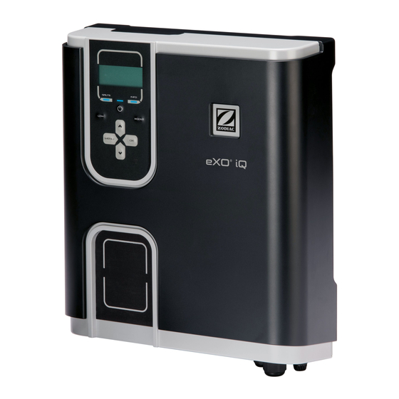
- Page 1 (iQ) / GenSalt OT Instructi ons for installati on and use - English Salt water chlorinator, pH/Redox regulati on Translati on of the original instructi ons in french pH Link / Dual Link More documents on: www.zodiac.com H0632500.A - 2018/09 - ES11--...
- Page 2 fi re. • Zodiac® heat pump, fi lter pump and fi lter appliances are compati ble with the most commonly used types of pool water treatment systems. • Do not touch the fan or moving parts and do not place a rod or your fi ngers in the vicinity of the moving parts during operati on of the appliance.
-
Page 3: Table Of Contents
CONTENTS ❶ Specifi cati ons 1.1 I Package content 1.2 I Technical specifi cati ons ❷ Installing the saltwater chlorinator 2.1 I Installing the cell 2.2 I Installing the temperature sensor (in depending to the model) 2.3 I Installing the fl ow switch (chlorinator only without pH Link or Dual Link modules) 2.4 I Installing the control box 2.5 I Electric connecti ons... -
Page 4: ❶ Specifi Cati Ons
• The distributi on or modifi cati on of this document in any way is prohibited, without prior authorisati on from Zodiac®. • Zodiac® is constantly developing its products to improve their quality. The informati on contained herein may therefore be modifi ed without noti ce. - Page 5 1.1.2 Opti onal pH Link or Dual Link modules pH Link Dual Link pH Link or Dual Link modules POD kit Hole saw for installing the POD kit Threaded sensor holder(s) pH sensor + pH 7 (x3) & pH 4 (x3) buff er soluti ons ORP sensor + ORP 470 mV (x3) buff...
-
Page 6: I Technical Specifi Cati Ons
1.2 I Technical specifi cati ons 1.2.1 Chlorinator eXO® (iQ) 10 eXO® (iQ) 18 eXO® (iQ) GenSalt OT eXO® (iQ) GenSalt OT 10 GenSalt OT 18 Nominal chlorine producti on 10 g/h 18 g/h 22 g/h 25 g/h 35 g/h Nominal output current 2.8 A 3.6 A... -
Page 7: ❷ Installing The Saltwater Chlorinator
❷ Installing the saltwater chlorinator 2.1 I Installing the cell • The cell must be installed on the piping aft er the fi ltering, aft er any measurement sensors and aft er any heati ng systems. Installing the saltwater chlorinator only Installing the chlorinator + opti onal module (Example with eXO®... - Page 8 2.1.2 GenSalt OT cell 7,5 cm 22,5 cm 27,5 cm 27,5 cm 16,5 cm 12,5 cm • The cell must be installed on a horizontal pipe to ensure an essenti ally horizontal fl ow of water through it, with no more than a 30 deg angle/slope. The pipe must have a free horizontal length of at least 30cm on which the cell will be installed.
-
Page 9: I Installing The Temperature Sensor (In Depending To The Model)
2.2 I Installing the temperature sensor (in depending to the model) • The water temperature sensor displays the water temperature value on the appliance screen and manages chlorinati on according to the temperature. The sensor must measure the temperature of the water upstream of any possible heati ng system. -
Page 10: I Installing The Control Box
2.4 I Installing the control box 31.5 cm 9.6 cm 36.4 cm • The control box must be installed in a dry venti lated equipment room protected against frost, with no pool maintenance chemicals or similar products stored nearby. • The control box must be installed at least 3.5 metres from the outer edge of the pool. Always comply with all applicable installati on codes and/or laws that may apply in the area of installati on. -
Page 11: I Electric Connecti Ons
2.5 I Electric connecti ons Many devices can be connected to the control box in order to control the pool equipment (fi lter pump, lighti ng, auxiliary systems, etc.). The appliance must be permanently plugged in to the power supply (power supply protected by a 30 mA residual current circuit breaker). - Page 12 Connecti on for the fl ow switch iAL RS485 Input Functi on not used – do not wire Connecti on dedicated to controlling the Zodiac® VSP RS485 Output variable-speed fi lter pump Functi on not used – do not wire...
- Page 13 2.5.3 Electrical connecti on steps • Identi fy the functi ons to be connected and identi fy the locati on of the cable clamp, see “2.5.2 Identi fying the functi ons to connect”. • Check that the cables used comply with the intended use and with the regulati ons in force. •...
- Page 14 2.5.4 Connecti ng a Zodiac® variable speed fi lter pump (in depending to the model) The Zodiac® variable speed fi lter pump must be connected in 2 places: - Mains supply to the «PUMP 230 V» connector. - RS485 cable (supplied with the pump) to the appliance’s «VSP RS485» connector in the following order:...
-
Page 15: ❸ Installing A Ph Link Or Dual Link Module
❸ Installing a pH Link or Dual Link module 3.1 I Installing the POD kit The POD Kit is a measuring chamber using patented Quick Fix® technology for installati on on a rigid 50 mm PVC pipe (with supplied adapter) or 63 mm PVC pipe (without adapter). It contains the following components: : The fl... - Page 16 3.1.2 Preparing the hose • Identi fy a suitable length (minimum 30 cm, without an elbow) of straight pipe. • Disassemble the POD kit to retrieve the EU (DN50 mm) type adapter provided with two perforati ons, see illustrati on •...
- Page 17 3.1.3 Installing the POD kit on the pipe • Click the 2 parts of the POD kit together around the pipe. For a 50 mm diameter pipe, use the adapter marked 'EU'. Do not use this adapter for a 63 mm diameter pipe, see illustrati on •...
-
Page 18: I Installing The Fl Ow Switch On The Pod Kit
3.2 I Installing the fl ow switch on the POD kit • Take the fl ow switch provided with the chlorinator control box. • Place it inside the housing provided for this purpose on the POD Kit and screw it down. •... -
Page 19: I Installing The Sensors On The Pod Kit
3.3 I Installing the sensors on the POD kit • Screw down the one or more sensor holders onto the POD kit, see illustrati on • Carefully unscrew the protecti on tube from the sensor, see illustrati on . Retain the protecti on tube for use when the sensor is stored during the winter. -
Page 20: I Installing The Ph Minus Injecti On And Sucti On Pipes
3.4 I Installing the pH minus injecti on and sucti on pipes • When handling chemical products, always use appropriate safety equipment (safety glasses, gloves and jacket). The peristalti c pump rotates in the clockwise directi on. The acid (pH minus) is therefore sucked into the left side of the pump and injected into the tank from the right side. - Page 21 3.4.2 Installing the pH minus sucti on pipe • Cut a suitable length of pipe from the coil supplied to connect the container of pH minus to the peristalti c pump. • Unscrew the connecti on cap and att ach the pipe to the connector on the inlet to the peristalti c pump, see illustrati on .
-
Page 22: ❹ Pool Preparati On
❹ Pool preparati on 4.1 I Water balance The water used must originate from a supply network compliant with Directi ve 98/83/EC on the quality of water intended for human consumpti on. To achieve opti mum water treatment, be sure to measure and adjust the values in line with the following recommendati ons: 4.1.1 Seasonal «restart»... -
Page 23: I Adding Salt
4.2 I Adding salt Every device operates with a recommended minimum salt rati o, see “1.2.1 Chlorinator”. In order for the chlorinator appliance to operate properly, and to protect the equipment, we recommend using salt (sodium chloride) as per standard EN 16401. 4.2.1 Determining the amount of salt to use on installing the appliance Example: •... -
Page 24: ❺ Use
❺ Use 5.1 I User interface • Before starti ng the appliance's chlorinati on functi on, make sure that all of the salt added to the pool has dissolved fully. Blue indicator on or blinking: Blue indicator on: See informati on or acti on to perform on- Water conducti vity too low (lack of salt, screen. - Page 25 5.2.3 Setti ng the ti me Setti ng the ti me is essenti al for programming the fi ltrati on ti me using "TIMERS" and the chlorinati on ti me using "SWC". The ti me is set the fi rst ti me the appliance is used. Follow the indicati ons below if you need to make any modifi cati ons to the ti me displayed: •...
- Page 26 5.2.5 Programming the fi ltrati on ti me using "TIMERS" The ti mers are used to defi ne the length of ti me for the fi lter pump to operate, and the length of ti me for the Salt Water Chlorinator (SWC) to produce chlorine.
- Page 27 ==> Zodiac® Variable-speed fi lter pump (in accordance to the model) • It is possible to program fi ltering ti mes using the "TIMERS" functi on for each speed available. • Select a speed using the butt ons. Press to confi rm.
- Page 28 5.2.6 Programming the chlorinati on ti me using "SWC" If a fi ltrati on program has been set, the chlorinati on program will be identi cal to the fi ltrati on program(s) by default. They can be changed, however the chlorinati on program(s) cannot be acti vated outside of the fi ltrati on Program(s) for safety reasons.
- Page 29 The chlorinator is capable of controlling two devices in additi on to the fi lter pump. It can for example control monochrome or multi colour Zodiac® lights. In all cases, the equipment must be connected to the chlorinator using the appropriate auxiliary line: •...
- Page 30 ==> Zodiac® multi colour lighti ng • Press and browse the menu using the butt ons. • Select a functi on or a colour and press to confi rm. • Press to exit. For multi colour lighti ng of another brand, only the «ON/OFF» management is possible.
- Page 31 5.2.10 Slave mode «Slave» mode relinquishes control of the chlorinati on functi on to an external controller. The external controller must be mode relinquishes control of the chlorinati on functi on to an external controller. The external controller must be connected to the connecti on point in the low voltage raceway, see «2.5 I Electric connecti ons».
- Page 32 5.2.11 Setti ng the durati on of polarity reversal The principle of polarity reversal is to eliminate the scaling that builds up on the electrodes by reversing the electrical current for a set length of ti me. By default, the cycle reverses every fi ve hours. Depending on locati on, water will be more or less hard (water hardness = TH).
-
Page 33: I Calibrati Ng The Sensors (If An Opti Onal Ph Link Or Dual Link Module Is Installed)
5.3 I Calibrati ng the sensors (if an opti onal pH Link or Dual Link module is installed) 5.3.1 Calibrati ng the pH sensor (blue) The pH sensor may be calibrated in 1 point calibrati on or 2 points (pH 4 and pH 7); 2 point calibrati on is recommended for more accurate measurement. - Page 34 5.3.2 Setti ng the pH setpoint Current Sensor Measure Setpoint Establishing the pH setpoint determines when acid will be added to the system to decrease the pH of the water. Default pH setti ng is 7.2. To fi nd out the value of the setpoint to be set, refer to Taylor’s watergram, see «4.1.3 Weekly analysis».
- Page 35 5.3.3 Calibrati ng the ORP sensor Current Sensor Measure (ORP = Redox) Setpoint The ORP sensor may be calibrated in 1 point (ORP 470 mV); Current setpoint is displayed on the Home screen whenever the device is ON. • Turn on power to the device. •...
- Page 36 5.3.4 Setti ng the ORP setpoint Establishing the ORP setpoint determines when chlorine is produced by the appliance. Free chlorine level should be checked every few days aft er initi al installati on. Default ORP setti ng is 700 mV. The setpoint value depends on the pool environment, its use, the rate of stabiliser present in the pool and so on.
- Page 37 5.3.6 Pausing of the pH Dosing Pump To prevent acid injecti on when it is not required: It is possible to stop the pH dosing pump for 8 hours. • Press and browse the menu using the butt ons. Press to confi...
-
Page 38: I Regular Use
5.4 I Regular use 5.4.1 Adjusti ng chlorine producti on From factory, the chlorinati on is set at 50 %. It can be set between 0 and 100 % in 10 % increments from the “main screen” by pressing . The set value is valid unti l the next modifi cati on. The term «standard»... - Page 39 5.4.4 "Cover" mode If the pool is equipped with a compati ble electric roller cover (contact closed = shutt er closed), this can be connected to the device in order to automati cally reduce chlorinati on upon closing the cover, this is known as «Cover» mode. Chlorinati on will resume at the level determined by the programming upon opening the compati ble electric cover.
-
Page 40: ❻ Maintenance
❻ Maintenance 6.1 I Cleaning the sensor(s) Sensor(s) must be cleaned every 2 months. • Turn off the fi lter pump. • Close all valves. • Remove the sensor and the sensor holder from the POD. • Rinse the sensor with tap water for 1 minute. •... -
Page 41: I Checking And Cleaning The Electrodes
6.2 I Checking and cleaning the electrodes The appliance is equipped with a smart polarity reversal system designed to prevent the electrode plates from scaling. The durati on of the polarity reversal can be changed, see “5.2.11 Setti ng the durati on of polarity reversal”. -
Page 42: I Washing The Pool Fi Lter (Backwash) (In Accordance To The Model)
6.3 I Washing the pool fi lter (backwash) (in accordance to the model) Backwash mode is used to quickly start/stop the fi lter pump (single- or variable-speed pump) in order to backwash the fi lter. • Press and browse the menu using the butt ons. -
Page 43: ❼ Troubleshooti Ng
❼ Troubleshooti ng • Before you contact your retailer, please carry out these few simple checks using the following tables if a problem occurs. • If the problem conti nues, contact your retailer. • : Acti ons to be performed by a qualifi ed technician only 7.1 I Appliance behaviour The informati on messages may be hidden by pressing for 4 seconds. - Page 44 7.1.2 Appliance WITH with pH Link or Dual Link module Message Possible Cause Soluti on • Check the pH sensor wiring on the control box and on the sensor holder. • The pH level is less than 5. • Check the operati on of the sensor using a sensor Check the operati on of the sensor using a sensor «LOW pH»...
-
Page 45: I Eff Ects Of The Stabiliser On The Chlorine And The Orp
7.2 I Eff ects of the stabiliser on the chlorine and the ORP A pool has a stabiliser content of 30 ppm and a pH of 7.4. 1 ppm free chlorine = 700 mV Therefore, the user can set their chlorinati on requirement to 700 mV to maintain a level of 1 ppm in the pool. If the level of stabiliser increases to 90 ppm, the ORP reading will be false. - Page 46 Your retailer Modèle appareil Appliance model Numéro de série Serial number Pour plus d’informations, enregistrement produit et support client : For more information, product registration and customer support: www.zodiac.com ZODIAC® is a registered trademark of Zodiac International, S.A.S.U., used under license.
Need help?
Do you have a question about the GenSalt OT Series and is the answer not in the manual?
Questions and answers