Table of Contents
Advertisement
INSTALLATION MANUAL
eXO
®
(all models)
WARNING
FOR YOUR SAFETY - This product must be installed and serviced by a licensed electrician in
accordance with SANS 10142-1 and local applicable regulations. Before installing this product, read
and follow all warning notices and instructions that accompany this product. Failure to follow warning
notices and instructions may result in property damage, personal injury, or death. Improper installation
and/or operation will void the warranty.
Improper installation and/or operation can create unwanted electrical hazard which can cause serious
injury, property damage, or death.
Advertisement
Table of Contents

Related Manuals for Zodiac eXO Series

Summary of Contents for Zodiac eXO Series
- Page 1 INSTALLATION MANUAL ® (all models) WARNING FOR YOUR SAFETY - This product must be installed and serviced by a licensed electrician in accordance with SANS 10142-1 and local applicable regulations. Before installing this product, read and follow all warning notices and instructions that accompany this product. Failure to follow warning notices and instructions may result in property damage, personal injury, or death.
-
Page 2: Table Of Contents
Section 6. Prepare and Balance the Pool ..15 pH Regulation Principle ..........15 Water Chemistry Table ..........15 Stabilizer (Cyanuric Acid) ..........15 For information on warranty and service in South Africa go to www.zodiac.co.za EQUIPMENT INFORMATION RECORD DATE OF INSTALLATION INSTALLER INFORMATION... -
Page 3: Section 1. Important Safety Instructions
Page 3 | Installation Manual ® Section 1. Important Safety Instructions READ AND FOLLOW ALL INSTRUCTIONS All electrical work must be performed by a licensed electrician and conform to all national, state, and local codes. When installing and using this electrical equipment, basic safety precautions should always be followed, including the following: DANGER To reduce the risk of severe injury or death, do not remove the suction fittings of your spa or hot tub. - Page 4 Page 4 | Installation Manual ® WARNING People with infectious diseases should not use a spa or hot tub. To avoid injury, exercise care when entering or exiting the spa or hot tub. Do not use drugs or alcohol before or during the use of a spa or hot tub to avoid unconsciousness and possible drowning.
-
Page 5: Section 2. System Overview
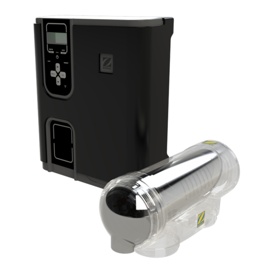
Page 5 | Installation Manual ® 2.1.2 Water Care Module Contents Section 2. System Overview Contents Before starting, check that you have the correct parts as indicated in Table 1. If any parts are missing or incorrect, please call your local distributor or technical support at 0860 887 665 for assistance. -
Page 6: Dimensions
Page 6 | Installation Manual ® Materials and Tools Dimensions 2.4.1 Controller 2.3.1 Controller Tools Needed for Installation 9.6 cm 31.5 cm • Power Drill • 7 mm Drill Bit - Hammer Drill Bit (only necessary to drill into brick or concrete) •... -
Page 7: Section 3. Plumbing
Page 7 | Installation Manual ® Section 3. Plumbing Put the unions onto the inlet and outlet pipes, The cell must be plumbed in a position that is see Figure 5. accessible for maintenance and within 2 meters of For 63 mm plumbing, glue the adapters the controller. -
Page 8: Section 4. Install Controller
Page 8 | Installation Manual ® Section 4. Install Controller The controller should be located at or near the equipment pad, at least 3.5 metres or more away Ø9 MM from the inside wall of the pool/spa, 1.5 metres off the ground, and within 2 meters of the cell. All national, state, and local codes are applicable. - Page 9 Page 9 | Installation Manual ® 4.3.2 Controller Enclosure Wiring Wire low voltage connections on the low voltage side of the enclosure, see Figure 10. Wire high voltage connections on the high voltage side of the enclosure, see Figure 10. Use the internal labels (low voltage - yellow, high voltage - orange) to identify connection points.
- Page 10 Page 10 | Installation Manual ® H0632100 Rev A CABLE IDENTIFICATION TNG EU SENS PUMP CELL TEMP FLOW iAL RS485 VSP RS485 COVER SLAVE AUX 2 12-24V H0632100 Rev A CABLE IDENTIFICATION TNG EU PUMP 230V MAINS AUX 230V SENS PUMP CELL TEMP FLOW iAL RS485...
-
Page 11: Module On The Controller
Page 11 | Installation Manual ® Section 5. Install the pH Link Module Drill the Pipe on the Controller Inspect the POD O-ring to ensure it is in good condition and properly seated. NOTE: The water care module is an optional accessory Press tabs to remove the upper POD housing and will not be included with all models. -
Page 12: Install The Pod Cap
Page 12 | Installation Manual ® Note the arrows on the upper housing Sensor indicating flow direction. Make sure the pod is Holder in proper orientation. Outlet Inlet Plug Flow Flow Figure 14. POD Orientation Assemble the POD around the pipe, the tabs will click into place. -
Page 13: Install The Ph Down Intake And Injection Lines
Page 13 | Installation Manual ® Install the pH Down Intake and NOTE: For a better fit, soften both ends of the tubing by immersing in warm water. Injection lines. Remove the threaded cap from the POD intake valve. Thread tubing through the hole in the cap, connect the tubing to the nipple on the POD and reattach the threaded cap. -
Page 14: Calibration Procedure
Page 14 | Installation Manual ® Calibration Procedure 5.7.2 Calibrate the pH Sensor The pH sensor (blue) can be calibrated in 1 or 2 To maintain accurate and reliable operation, points. We recommend 2-point calibration for a the sensors must be calibrated before using more reliable measurement throughout the season. -
Page 15: Section 6. Prepare And Balance The Pool
Page 15 | Installation Manual ® Section 6. Prepare and Balance the Pool pH evolution 8,20 pH Regulation Principle 8,15 8,10 The amount of chlorine needing to be produced is 8,05 dictated by the pH level in the pool. As the pH level 8,00 rises, the amount of chlorine must be increased to 100%... -
Page 16: Section 7. Operation
Page 16 | Installation Manual ® Section 7. Operation User Interface Overview CAUTION Before activating the chlorination function of your system, ensure that all salt added to the pool has completely dissolved. LED indicates information or LED indicates low salt/minerals error message on screen or poor water conductivity On, Off... - Page 17 Page 17 | Installation Manual ® ignored for the duration of the Boost mode. Once Cover mode will stop as soon as the cover is Boost mode completes, the controller and filter completely open. pump will resume programmed operations. If the controller is equipped with a Dual Link module we do not recommend connecting the NOTE: If the device is equipped with a Dual Link module, the Boost mode will not take the ORP...
-
Page 18: Section 8. Menu And Settings
Page 18 | Installation Manual ® Section 8. Menu and Settings Press to select “Filter Pump” Filter Pump then press to select “Variable Speed” Both single and variable speed pumps can be then press connected to and operated by the controller. The user interface will prompt “Variable Speed Plgd to Device”. -
Page 19: Aux/Lights
-FAT TUESDAY -DISCO TECH 8.2.1 Assign Lights Press Note: colour sequence is relevant for Zodiac colour to select “Aux/Light” then press lights only. If other manufacturers lights are to select “Assign Lights” then press installed the colour selection will vary to select “Aux 2”... -
Page 20: Ph Sensor Calibration
Page 20 | Installation Manual ® pH Sensor Calibration The pH sensor may be calibrated in 1 point calibration or 2 point calibration (pH 4 and pH 7); 2 point calibration is recommended. Turn on power to the controller. Turn off the pool pump and close valves as necessary to isolate the cell and sensors. -
Page 21: Setpoint(S)
Page 21 | Installation Manual ® Setpoint(s) Prime and Test the pH Dosing Pump Current setpoints are displayed on the Home screen whenever the controller is ON. The dosing pump is deactivated during the first 8 hours of the device in order to prevent acid 23:04 ON exposure during installation. -
Page 22: Programming/Timers
Page 22 | Installation Manual ® Programming/Timers 8.6.3 Single Speed Programming The controller has two internal operating timers. Press The timers are used to define the length of time for to select “Programming” the filter pump to operate, and the length of time then press for the Salt Water Chlorinator (SWC) to produce to select “Filter Pump”... - Page 23 Page 23 | Installation Manual ® 8.6.4 Variable Speed Programming to select the minutes for the SWC off time then press Press to select “Programming” Press to exit. then press MAIN MENU PROGRAMMING -PROGRAMMING < -SWC < to select “Filter Pump” then press -LOW MODE -AUX/LIGHTS -SLAVE MODE...
-
Page 24: Reversing
Adjusting your cell reversal times will result in voiding must be connected to the “Slave” connection point of warranty. You must consult with Zodiac on 1300 763 in the low voltage raceway see Table 5 and Figure 021 or your local pool care professional before making 10 for wiring details. -
Page 25: Section 9. Inspecting And Cleaning The Electrode
Passive winterization calls for the pool to be shut without immersing the terminals. down. Water levels will need to be lowered and the We recommend using Zodiac Salt Chlorinator piping will need to be drained. The cell electrode Cell Cleaner to clean the electrode. However, can be left in place with isolation valves open. -
Page 26: Section 11. Troubleshooting
Page 26 | Installation Manual ® Section 11. Troubleshooting When there is an error condition, a message is displayed on the screen and the “INFO” LED flashes. When an error is linked to conductivity (low conductivity) the “SALTS” LED is ON. When the error situation is corrected, the error message and LED illumination ends automatically. - Page 27 Page 27 | Installation Manual ® NOTES...
- Page 28 2012, South Africa 0860 887 665 | www.zodiac.co.za ZODIAC ® is a registered trademark of Zodiac International, S.A.S.U., used under license. All trademarks referenced herein are the property of their respective owners. ©2018 Zodiac Pool Systems, Inc. H0642500 REV A...
Need help?
Do you have a question about the eXO Series and is the answer not in the manual?
Questions and answers