
Related Manuals for Zodiac eXPERT


Summary of Contents for Zodiac eXPERT
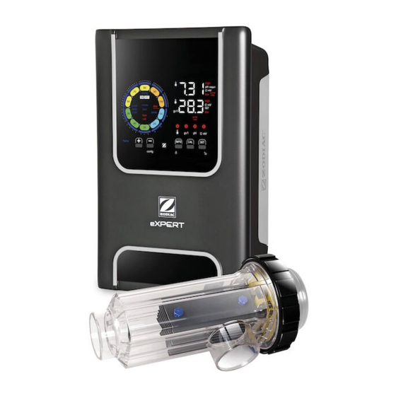
- Page 1 Instructions for installation and use - English Salt water chlorinator Translation of the original instructions in french More documents on: www.zodiac.com H070800.A - 2020/12...
- Page 2 • The distribution or modification of this document in any way is prohibited, without prior authorisation from Zodiac®. • Zodiac® is constantly developing its products to improve their quality. The information contained herein may therefore be modified without notice. GENERAL WARNINGS •...
- Page 3 WARNINGS ASSOCIATED WITH ELECTRICAL APPLIANCES • The power supply to the appliance must be protected by a dedicated 30 mA Residual Current Device (RCD), complying with the standards and regulations in force in the country in which it is installed. •...
-
Page 4: Table Of Contents
CONTENTS ❶ Specifications 1.1 I Contents 1.2 I Technical specifications 1.3 I Dimensions 1.4 I Operating principle ❷ Installing the salt water chlorinator 2.1 I Installing the electrolytic cell 2.2 I Installing the flow switch 2.3 I Installing the sensors (pH & pH/ORP, depending on model) 2.4 I Installing the pH pump (pH & pH/ORP, depending on model) 2.5 I Installing the control box 2.6 I Connecting auxiliary devices ❸... -
Page 5: ❶ Specifications
❶ Specifications 1.1 I Contents eXPERT eXPERT eXPERT pH pH/ORP Control box Electrolysis cell Wall-mounting bracket kit Flow switch with installation kit Sensor holder kit pH sensor (blue) + pH 7 and pH 4 buffer solutions PH pump kit: peristaltic pump, filter, injector, 2 metre suction... -
Page 6: I Technical Specifications
1.2 I Technical specifications eXPERT Operating water temperature 5 - 40°C Volume of treated water (m³) (temperate climate, 8h/day filtration) Nominal chlorine production 7 g/h 12 g/h 21 g/h 30 g/h 40 g/h Nominal output current 3.5 A 3.5 A 6.5 A... -
Page 7: I Dimensions
1.3 I Dimensions 1.3.1. Cell 157 mm 332 mm 63 mm 1.3.2. Flow switch (and installation kit) 1.3.3. Control box 230 mm 120 mm 1.4 I Operating principle The chlorinator is composed of an electrolytic cell (containing electrodes) and a control box. When the salt water from the swimming pool passes through the cell, the current generated by the electrodes creates an electrolytic reaction which transforms the chloride ions (from the salt in the swimming pool) into chlorine gas. -
Page 8: ❷ Installing The Salt Water Chlorinator
❷ Installing the salt water chlorinator 2.1 I Installing the electrolytic cell • The cell must always be the last element placed on the pool return pipe (see § “2.1.1. Installing the cell and the sensor holder (depending on model)”). • It is always recommended to install the cell on a by-pass. This assembly is mandatory if the flow is in excess of 18 m³/hour to avoid head loss. - Page 9 2.1.2. Connecting the cell and the sensor holder • Do not glue sensor holder and cell directly together : use a PVC union coupler (not included) between sensor holder and cell. It is also possible to use a 6-to-8 cm PVC tube, Ø63 cm, with one beveled end (the one to glue to the cell inlet) and a PVC sleeve (to glue between the PVC tube and the sensor holder).
- Page 10 • Identify the input points on the cell for each function, according to the appliance model:...
- Page 11 • Attach the connectors by successively installing the terminals, washers, and nuts (see following table). • Carefully tighten the top nut by hand (risk of irreversible leakage). eXPERT 7 exPERT 12 eXPERT 21 eXPERT 30 exPERT 40 • Connect the cell to the control box, see§ “2.5 I Installing the control box”.
-
Page 12: I Installing The Flow Switch
2.2 I Installing the flow switch • Failure to comply with these instructions could lead to the destruction of the cell. The manufacturer cannot be liable in this case. • The flow switch has a direction for installation (arrow indicated on it showing the flow direction for the water). -
Page 13: I Installing The Sensors
2.3 I Installing the sensors (pH & pH/ORP, depending on model) • Never wipe the sensor using a cloth or paper tissue, as this may damage it. • A badly-installed sensor may give false readings and cause inappropriate operation of the appliance. Neither the manufacturer nor the appliance shall be liable in this event. -
Page 14: I Installing The Ph Pump
2.4 I Installing the pH pump (pH & pH/ORP, depending on model) • When handling chemical products, always use appropriate safety equipment (safety glasses, gloves, jacket and mask). • The pH pump is a peristaltic pump that rotates in the clockwise direction: it sucks up acid (pH-minus) to inject into the pool. - Page 15 2.4.2. Installing the pH minus suction line • Cut a suitable length of transparent hose from the coil (supplied) to connect the container of pH-minus to the pH pump. • Unscrew the connector cap and attach the hose to the connector at the inlet of the pH pump, see figure .
-
Page 16: I Installing The Control Box
2.5 I Installing the control box 2.5.1. Placement of the control box The control box must be installed in a dry ventilated technical room protected against frost, with no pool • maintenance products or similar products stored nearby. The control box must be installed at a distance of at least 3.5 m from the outside edge of the pool. Always •... -
Page 17: I Connecting Auxiliary Devices
2.5.2. Connecting the control box • Before beginning, disconnect all potential power supplies to the appliance. • Check that the cables used comply with the intended use and with the regulations in force. • Identify the connection point for each desired function at the bottom of the control box: Electrolysis cell pH sensor (BNC connector)* ORP sensor (BNC connector)*... - Page 18 2.6.2. Detail of connections Contact closed (ON) Contact open (OFF) Activate the function Pool cover closed: reduced Pool cover open : 100% See§ “4.3.7. “Cover”: Pool Cover production (10% to 90%) production Connecting a pool cover” No external chlorination controller (ORP or PPM) or External chlorination controller See §...
- Page 19 2.6.3. pH pump connection (for pH - PH/ORP models) • Above 500mA, the pH pump connection must be protected by a circuit breaker with a suitable residual current protection device and controlled using a relay. Installation with provided pH pump Alternative solution if a bigger pump is used...
-
Page 20: ❸ Preparing The Pool
❸ Preparing the pool 3.1 I Balance the water The water used must originate from a supply network compliant with Directive 98/83/EC on the quality of water intended for human consumption. In order for the water to be treated optimally, carry out measurements and adjust the values in accordance with the following recommendations: Seasonal analyses in "preparation for re-use"... -
Page 21: I Add Salt
3.2 I Add salt Every appliance must be operated with a minimum recommended salt level, see § “1.2 I Technical specifications”. In order for the chlorinator appliance to operate properly, and to protect the equipment, we recommend using salt (sodium chloride) as per standard EN 16401. 3.2.1. Determining the quantity of salt to be used when installing the appliance Example: A. -
Page 22: ❹ Use
❹ Use 4.1 I User interface 4.1.1. User interface presentation Buttons touch areas BROWSING BUTTONS - Display the values for water temperature, salt concentration, pH & ORP values and setpoints (depending on model) and Boost mode management. - Browse and exit the Configuration menu - Calibrate - Configure values and confirm - Reduce production or a selected value... - Page 23 Water temperature display ORP mV display (shows chlorination efficiency) Setpoint display Chlorination is off (setpoint = 0%) ALARMS Measured temperature too high or too low (non-blocking) Measured salt concentration too high or too low (non-blocking) Measured pH too high or too low (non-blocking) Measured ORP value too high or too low (non-blocking) Values too high Values too low...
-
Page 24: I Routine Use
4.2 I Routine use 4.2.1. Adjusting chlorine production Chlorine production can be manually adjusted between 0 and 100% in intervals of 10%, by using : the chlorine production setpoint indicator is adjusted (in the following example, for production at 70%). The setpoint value remains valid until next modified. 4.2.2. Displaying values and configuring setpoints The pH and ORP values are automatically displayed on the home screen. -
Page 25: I Settings That Can Be Accessed In Configuration Mode
4.2.3. "Boost" mode In some cases, the pool may require a higher than normal chlorine level, for example during times of high use, bad weather or at the start of the pool season. "Boost" mode is used to quickly increase the chlorine level. It operates for 24 consecutive hours at a 100% production rate. - Page 26 • Press (see number of required presses in the following table) to access the desired function. Number Screen display Function Additional information presses • Shows the appliance model • See § «4.3.2. Appliance information»“ • Displaying and resetting the • See § «4.3.3. Displaying and resetting the number of operating hours of the number of operating hours of the cell or cell or the pH pump...
- Page 27 4.3.2. Appliance information Show the appliance model Show the current software version • Press for 5 seconds. • Press for 5 seconds then press . The soft- The appliance model is displayed on the screen ware version is displayed on the screen. (platform version and g/h power).
- Page 28 At the time of reversal, chlorination is stopped for a few minutes. No message is displayed on the screen. Normal operation resumes after reversal is complete. 4.3.5. "Flow": Activating the flow switch This mode is activated by default. To deactivate the use of the flow switch: •...
- Page 29 4.3.7. "Cover": Connecting a pool cover If the pool is equipped with a compatible electric cover, it can be connected to the appliance in order to automatically reduce chlorination when it is closed: this is the "Cover " mode. It is then automatically activated when the pool cover is closed, and chlorination resumes at the level determined by the programming on opening the compatible electric pool cover.
- Page 30 4.3.10. “Pump stop”: pH pump stop over feed alarm (pH - PH/ORP models) The pH pump stops rotating if the pH setpoint has not been reached after a given time, resulting in the display of an alarm. By default, this programmed safety time is 60 minutes. To adjust it (minimum value: 1 min - maximum value: 120 min): •...
- Page 31 4.3.13. Setting the “Temperature” alarm triggering When the measured temperature is outside the configured range, an alarm is displayed. The recorded default range is 5°C - 40°C. To adjust it: • From the Configuration/ mode, press : the minimum value (indicated by “LO”) flashes. •...
- Page 32 4.3.15. User interface energy saving mode By default, the screen power saving mode is activated and an appliance which is unused goes into standby: an animated production indicator is displayed and the measured values are not visible. To deactivate this mode: •...
-
Page 33: I Calibrating The Sensors (Ph Or Ph/Orp Models)
4.4 I Calibrating the sensors (pH or pH/ORP models) 4.4.1. Choosing the calibration mode • The pH sensor and the ORP sensor can be calibrated in "Standard" mode • The pH sensor can also be calibrated in "Fast" mode Standard mode (pH & ORP) Fast mode "Fast"... - Page 34 4.4.4. Configuring the pH setpoint The pH setpoint configuration determines the time when acid is added to the system to reduce the water's pH. The default value of the pH setpoint is 7.2. To determine the value of the setpoint to be configured, refer to Taylor's balance, see § “3.1 I Balance the water”. •...
-
Page 35: ❺ Remote Control Using Fluidra Connect And Nn App
❺ Remote control using Fluidra Connect and NN app 5.1 I Wiring the chlorinator to Fluidra Connect power center The chlorinator is a connectable device: information on the status of the swimming pool can be accessed at any moment (to check the dashboard, change a setting, etc.) from a smartphone or tablet via the Fluidra Connect NN app. For this, the chlorinator must first be connected to a Connect &... -
Page 36: I Managing The Chlorinator Remotely With Nn App
5.2 I Managing the chlorinator remotely with NN app Before you install the app, you must: • Use a Wi-Fi-enabled smartphone or tablet, • Use a Wi-Fi network with a reasonably strong signal when connecting to the chlorinator. • Have your home Wi-Fi network password at the ready. •... -
Page 37: ❻ Maintenance
❻ Maintenance 6.1 I Sensor maintenance The sensors must be cleaned every 2 months. • Stop the filter pump. • Close all valves. • Remove the sensor and the sensor holder. • Rinse the sensor in tap water for 1 minute. • Shake it to remove any residual water. To prevent damage to the active part, do not rub and do not dry with a cloth. -
Page 38: I Inspecting And Cleaning The Electrodes
6.2 I Inspecting and cleaning the electrodes The appliance is equipped with a smart polarity inversion system designed to prevent the electrode plates from scaling. The polarity reversal time can be modified, see § “4.3.4. “Reverse direct”: Reversal adjustment for cell cleaning”. However cleaning may be required in regions where the water is very hard. •... -
Page 39: I Peristaltic Pump Maintenance
6.3 I Peristaltic pump maintenance • To prevent the pump from operating when empty, check the level of the pH-Minus (acid) container every 2 to 12 months, depending on your installation (see table below). HYDROCHLORIC HYDROCHLORIC SULFURIC ACID ACID ACID Very corrosive atmosphere Corrosive atmosphere Non-corrosive atmosphere (installation not recommended) -
Page 40: I Winterising
6.4 I Winterising The appliance is fitted with a protection system limiting chlorine production in poor operating conditions such as cold water (winter) or low salt. • Active winterising = filtering operational in winter: below 10°C it is preferable to switch off the appliance. Above this temperature you can leave it running. -
Page 41: ❼ Troubleshooting
❼ Troubleshooting • Before you contact the retailer, carry out these few simple checks using the following table if a problem occurs. • If the problem is not resolved, contact your retailer. • : Actions to be performed by a qualified technician only 7.1 I User alerts Message Possible cause... -
Page 42: I Effects Of The Stabilising Agent On Chlorine And Orp
• Water flow problem: • Check the pump, the filter, the skimmer(s) and the - Filter pump failure, by-pass valve(s). Clean them if necessary. - Filter and/or the skimmer(s) are dirty, • Check the wire connections (flow switch). - Disconnection or failure of the flow •... - Page 43 Pour plus d’informations, enregistrement produit et support client : For more information, product registration and customer support: www.zodiac.com ©2020 Zodiac Pool Systems LLC. All rights reserved. ZODIAC® is a registered trademark of Zodiac International, S.A.S.U., used under license. All other trademarks are the property of their respective owners.
Need help?
Do you have a question about the eXPERT and is the answer not in the manual?
Questions and answers