Sign In
Upload
Manuals
Brands
Kontron Manuals
Racks & Stands
KISS 4U V3
Kontron KISS 4U V3 Manuals
Manuals and User Guides for Kontron KISS 4U V3. We have
3
Kontron KISS 4U V3 manuals available for free PDF download: User Manual
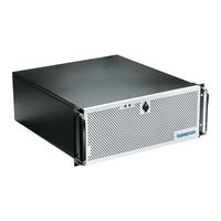
Kontron KISS 4U V3 User Manual (83 pages)
Brand:
Kontron
| Category:
Industrial PC
| Size: 5 MB
Table of Contents
Symbols
6
For Your Safety
7
High Voltage Safety Instructions
7
Special Handling and Unpacking Instruction
7
Lithium Battery Precautions
8
General Instructions on Usage
8
Quality and Environmental Management
8
Disposal and Recycling
8
WEEE Compliance
8
Table of Contents
9
List of Tables
11
List of Figures
12
1/ Introduction
13
Figure 1: KISS 4U V3 ADL
13
2/ General Safety Instructions
15
Instructions Générales de Sécurité
16
Electrostatic Discharge (ESD)
17
Grounding Methods
17
Instructions for the Lithium Battery
18
Operation of Laser Source Devices
19
3/ Shipment and Unpacking
20
Packaging
20
Unpacking
20
Scope of Delivery
20
Accessories and Spare Parts
20
Table 1: Scope of Delivery
20
Table 2: Accessories and Spares Parts
20
Product Identification Type Label
21
Figure 2: Type Label Example
21
4/ Product Features
22
Figure 3: Rackmount Variant (Closed Front Flap)
22
Figure 4: Desktop Variant (Closed Front Flap)
22
Figure 5: Rackmount Variant (Opened Front Flap)
22
Figure 6: Desktop Variant (Opened Front Flap)
22
Front Side
23
Figure 7: Front Side (Front Flap Closed)
23
Front Flap
24
Figure 8: Front Panel (Front Flap Open)
24
Drive Bays
25
Handle Brackets
25
Figure 9: Drive Bays
25
Figure 10: Handle Bracket
25
Fan Assembly
26
Figure 11: Fan Assembly
26
Filter Pad and Filter Pad Holder
27
Power Button
27
Figure 12: Power Button
27
Power LED and HDD LED
28
USB Ports
28
Table 3: Power LED and HDD LED Activity
28
Figure 13: LED Indicators
28
Figure 14: USB 3.2 Gen 1 Port
28
Rear Panel
29
Figure 15: Rear Panel
29
Display Port (DP)
30
Usb 3.2
30
Lan
30
Table 4: Display Resolution
30
Table 5: Display Order Priority
30
Audio
31
Serial Ports (COM)
31
Power Supply Units
32
Figure 16: Single PSU (600 W)
32
Potential Equalization Stud
33
Table 6: Redundant PSU LED Description
33
Figure 17: Redundant 500 W PSU
33
PCIE/PCI Expansion Card Slots
34
Side
35
Figure 18: Left Side
35
Figure 19: Right Side
35
Cover
36
Figure 20: Cover Underside
36
System Configuration
37
Figure 21: Example of KISS 4U V3 ADL Configuration
37
5/ System Expansion
38
Before Expanding
38
Mass Storage (Internal)
38
Drive Bays
38
Table 7: Mass Storage Devices
38
Table 8: Drive Bays
38
Expansion Cards
39
Reference Pcie Expansion Card
39
Table 9: Pcie/Pci Expansion Card Slot Allocation
39
Table 10: Reference KISS 4U V3 ADL Pcie Expansion Cards
39
6/ Thermal Management
41
Active Cooling
41
Temperature Sensor
41
Minimum System Clearance
41
Third Party Components
42
7/ Assembly
43
Before Assembling the Product
43
Opening and Closing the Cover
43
Figure 22: Loosening Knurled Screw (Front Panel)
43
Figure 23: Loosening Knurled Screws (Rear Panel)
44
Figure 24: Pull and Release the Cover
44
Figure 25: Removing the Cover
44
Installing and Removing Pcie/Pci Expansion Cards
45
Figure 26: Short and Long Brackets, and PCB Holder
45
Figure 27: Steps to Remove/Install the Short and Long Brackets
46
Installing and Removing the Handle Brackets
47
Figure 28: Removing the Handle Brackets
47
Installing and Removing the Front Flap
48
Installing the Rubber Feet (Option)
48
Figure 29: Front Flap Side-Plate (Left and Right)
48
Installing Slide Rails (Option)
49
Figure 30: Slide Rail Inner Part
49
Figure 31: Slide Rail in Pulled-Out Position
49
Figure 32: Slide Rail in Pushed-In Position
50
Figure 33: Assembling the Slide Rails in an Industrial Rack Cabinet
50
8/ Installation
51
Before Installing
51
Installing as a Desktop
52
Installing in a 19" Industrial Rack Cabinet
52
9/ Starting up
54
Before Starting
54
Connecting the Power Supply
54
Figure 34: Input Power Socket
54
Connecting to the Redundant Power Supply (Option)
55
Figure 35: Redundant Power Supply
55
Switching on
56
Operating System and Hardware Component Drivers
56
Figure 36: Power Button
56
10/ Bios
57
Starting the BIOS
57
BIOS Setup Menus
57
BIOS Navigation
58
BIOS Update
58
Updating the BIOS
58
Table 11: Navigation Hot Keys in the Legend Bar
58
Figure 37: BIOS FTP Server
58
Recover BIOS
59
11/ Product Specifications
60
Block Diagrams
60
Figure 38: Block Diagram KISS 4U V3 ADL
60
Hardware Specification
61
Table 12: Hardware Specification
61
Software Specification
62
Power Specification
62
Table 13: Software Specification
62
Table 14: Electrical Specification
62
Environmental Specification
63
Table 15: Environmental Specification
63
Mechanical Specification
64
Compliance
64
Table 16: Mechanical Specification
64
Table 17: CE Compliance
64
Table 18: International Compliance
65
12/ Standard Interfaces- Pin Assignments
66
DP Port Pin Assignment
66
USB 3.2 Gen 2/1 Pin Assignment
66
Table 19: DP V1.4A Pin Assignment
66
Table 20: USB 3.2 Gen 1 Pin Assignment
66
USB-C 3.2 Gen 2 Port Pin Assignment
67
2.5 Gbe/1.0 Gbe Pin Assignment
67
Table 22: USB 3.2 Gen 2 Type C Pin Assignment
67
Table 23: LAN (RJ45) Connector Pin Assignment
67
COM Port Pin Assignment
68
Audio Jack Connector Pin Assignment (Line-In, Line-Out, MIC-In)
68
Table 24: RS232 Connector Pin Assignment
68
Table 25: Audio Jack Pin Assignment
68
M.2 Key M (NVME SSD) Socket Pin Assignment
69
Table 26: M.2 Key M Socket Pin Assignment
69
Jumpers
70
Recover BIOS Jumper
70
Table 27: Recover BIOS Jumper
70
Figure 39: Recover BIOS Jumper
70
13/ Maintenance and Prevention
71
Before Maintaining the Product
71
Cleaning the Product
71
Cleaning the Filter Pad
71
Figure 40: Front Side with Filter Pad Holder
72
Replacing the Fan Assembly
73
Figure 41: Fan Assemble Without Filter Pad Holder
73
Figure 42: Filter Pad Holder (Without Filter Pad)
73
Figure 43: Filter Pad Holder (with Filter Pad)
73
Figure 44: Filter Pad
73
Figure 45: Removing the Fan Assembly
74
Figure 46: Fan Compartment (Without Fan Assembly)
74
Replacing the Faulty Redundant PSU
75
Replacing the Lithium Battery
76
Replacing a M.2 SSD Module
76
14/ Storage and Transportation
78
Storage
78
Transportation
78
15/ Technical Support
79
Returning Defective Merchandise
79
16/ Warranty
81
Limitation/Exemption from Warranty Obligation
81
Appendix: List of Acronyms
82
Table 28: List of Acronyms
82
About Kontron
83
Advertisement
Kontron KISS 4U V3 User Manual (72 pages)
Brand:
Kontron
| Category:
Desktop
| Size: 5 MB
Table of Contents
Symbols
6
For Your Safety
7
High Voltage Safety Instructions
7
Special Handling and Unpacking Instruction
7
Lithium Battery Precautions
8
General Instructions on Usage
8
Quality and Environmental Management
8
Disposal and Recycling
8
WEEE Compliance
8
Table of Contents
9
List of Tables
11
List of Figures
11
1 / General Safety Instructions for IT Equipment
13
Operation of Laser Source Devices
15
Electrostatic Discharge (ESD)
15
Grounding Methods
15
Instructions for the Optional Lithium Battery
16
2 / Introduction
17
3 / Scope of Delivery
18
Accessories and Spare Parts
18
Shipment, Packaging and Unpacking
18
Type Label and Product Identification
18
Table 1: Scope of Delivery
18
Table 2: Accessories and Spares Parts
18
Figure 1: Type Label Example
18
4 / Product Description
19
Figure 2: Rackmount Variant (Closed Front Access Panel)
19
Figure 3: Tower Variant (Closed Front Access Panel)
19
Figure 4: Desktop Variant (Closed Front Access Panel)
19
Figure 5: Rackmount Variant (Opened Front Access Panel)
19
Figure 6: Tower Variant (Opened Front Access Panel)
19
Figure 7: Desktop Variant (Opened Front Access Panel)
19
Front Side
21
Figure 8: Rackmount Variant with Front Access Panel Closed
21
Figure 9: 19" Handle Bracket
21
Figure 10: Front Side with Front Access Panel Opened
22
Figure 11: Front Side (Tower Variant) with Front Access Panel Closed
22
Power Button
23
USB Ports
23
Figure 12: Power Button
23
Figure 13: USB 2.0 Ports on the Front Side
23
LED Indicators
24
SYSID Button
24
Table 3: LED Indicators
24
Figure 14: LED Indicators
24
Figure 15: SYSID Button
24
Front Access Panel
25
Fan Assembly
25
Filter Pad and Filter Pad Holder
25
Drive Bays
26
Rear Side
27
Figure 16: Rear Side
27
External Interface Panel KISS 4U V3 SKX
28
Figure 17: External Mainboard Interface
28
Power Supply Unit (PSU)
30
Potential Equalization Stud
30
Figure 18: ATX PSU (860 W)
30
Pcie Slot Brackets
31
Figure 19: Pcie Expansion Card Slot Numbering
31
Sides (Left and Right)
32
Figure 20: Left Side View
32
Figure 21: Right Side View
32
Cover
33
Figure 22: Cover Underside
33
Internal View
34
Figure 23: Internal View
34
Bottom Side View (Tower Variant)
35
Figure 24: Bottom Side View (Tower Variant) with Rubber Feet Position
35
5 / System Expansion
36
System Memory
36
Drive Bay Combinations
36
Table 4: Drive Bay Combinations
36
Pcie Slots
37
Graphics Processing Unit (GPU) Cards
37
Network Card
37
Table 5: Pcie 3.0 Expansion Card Slots/Type
37
6 / Thermal Considerations
38
Active Cooling
38
Minimum System Clearance
38
Third Party Components
38
7 / Assembly
39
Opening and Closing the Cover
39
Figure 25: Loosening Front Side Knurled Screw
39
Figure 26: Loosening Rear Side Knurled Screws
39
Figure 27: Releasing the Cover
40
Figure 28: Removing the Cover
40
Accessing Internal Components
41
Installing /Removing Expansion Cards
41
Figure 29: Card Hold down Brackets (Short and Long)
41
Figure 30: Step to Remove the Card Hold down Brackets
42
8 / Installation
44
Attaching the Rubber Feet
44
Removing the Handle Brackets
45
Removing the Front Access Panel and Front Access Panel Side-Plates
45
Figure 31: Front Access Panel Side-Plate and Handle Bracket
45
Installing as a Desktop
46
Installing in a 19" Industrial Rack
46
Installing Slide Rails (Option)
47
Figure 32: Slide Rail (Inner Part) on a KISS 4U V3 SKX
48
Figure 33: Slide Rail in the Pulled-Out Position
48
Figure 34: Slide Rail in the Pushed-In Position
48
Installing as a Tower
49
Figure 35: Assembling Slide Rails in an Industrial Rack Cabinet
49
9 / Starting up
50
Connecting the Power Connection
50
Loss of AC Power
51
Operating System (OS) and Hardware Components Drivers
51
10 / Maintenance and Prevention
52
Cleaning the Filter Pad
52
Figure 36: Filter Pad Holder on the Front Side
52
Figure 37: Fan Assembly Without Filter Pad Holder
53
Figure 38: Filter Pad Holder Without Filter Pad
53
Figure 39: Filter Pad Holder with Filter Pad
53
Figure 40: Filter Pad
53
Replacing the Fan Assembly
54
Figure 41: Removing the Fan Assembly
54
Figure 42: Fan Compartment (Without Fan Assembly)
54
Figure 43: Fan Assembly Front Side
55
Figure 44: Fan Assembly Rear Side
55
Replacing the Lithium Battery
56
11 / Technical Data
57
Block Diagram
57
Figure 45: Block Diagram KISS4U V3 SKX
57
Technical Specification
58
Table 6: Technical Specification
58
Mechanical Specification
60
Environmental Specification
60
Table 7: Mechanical Specification
60
Table 8: Environmental Specification
60
Directives and Standards
61
Table 9: Directives and Standards
61
12 / Standard Interfaces - Pin Assignments
62
PS/2 Keyboard Mouse Connector
62
USB 2.0 Port
62
USB 3.1 Gen 1 and USB 3.1 Gen 2 ( Type A) Port
62
USB 3.1 Gen 2 (Type C) Port
63
Ethernet Connector
63
Audio 8-Channel (2, 4, 5.1, or 7.1 Channel Configurations)
64
S/PDIF Port
64
13 / Bios
65
Starting the Uefi BIOS
65
BIOS Update
66
Using the BIOS Flashback Button
66
Table 10: Navigation Hot Keys Available in the Legend Bar
66
14 / Technical Support
68
Returning Defective Merchandise
68
15 / Storage and Transportation
69
Storage
69
Transportation
69
16 / Warranty
70
Limitation/Exemption from Warranty Obligation
70
Appendix A: List of Acronyms
71
Table 11: List of Acronyms
71
Kontron KISS 4U V3 User Manual (70 pages)
Brand:
Kontron
| Category:
Racks & Stands
| Size: 6 MB
Table of Contents
Symbols
6
For Your Safety
7
High Voltage Safety Instructions
7
Special Handling and Unpacking Instruction
7
Lithium Battery Precautions
8
General Instructions on Usage
8
Quality and Environmental Management
8
Disposal and Recycling
8
WEEE Compliance
8
Table of Contents
9
List of Tables
11
List of Figures
11
1 / General Safety Instructions for IT Equipment
13
Operation of Laser Source Devices
14
Figure 1: Laser Radiation Warning Label
14
Electrostatic Discharge (ESD)
15
Grounding Methods
15
Instructions for the Lithium Battery
15
2 / Introduction
16
3 / Scope of Delivery
17
Accessories and Spare Parts
17
Shipment, Packaging and Unpacking
17
Type Label
17
Table 1: Scope of Delivery
17
Table 2: Accessories and Spares Parts
17
Figure 2: Type Label Example
17
4 / Product Description
18
Figure 3: Rackmount Variant (Closed Front Access Panel)
18
Figure 4: Desktop Variant (Closed Front Access Panel)
18
Figure 5: Rackmount Variant (Opened Front Access Panel)
18
Figure 6: Desktop Variant (Opened Front Access Panel)
18
Figure 7: Front Side with Front Access Panel Closed
19
Figure 8: Handle Bracket
19
Front Side
19
Figure 9: Front Side with Front Access Panel Open
20
USB Ports
21
Controls and Indicators
21
Figure 10: Power Button and USB 2.0 Ports
21
Front Access Panel
22
Table 3: Power LED and HDD LED Activity
22
Figure 11: LED Indicators
22
Fan Assembly
23
Filter Pad and Filter Pad Holder
23
Figure 12: Fan Assembly
23
Drive Bays
24
Table 4: Drive Bay
24
Figure 13: Rear Side with Mainboard
25
Rear Side
25
Figure 14: Rear Side with PICMG 1.3(Full-Size) SBC
26
Interfaces on the Rear Side
27
Figure 15: External Mainboard Interface Panel KISS 4U V3 CFL
27
Figure 16: External Mainboard Interface Panel KISS 4U V3 SKW
27
Additional Serial Ports
28
Figure 17: External Mainboard Interface Panel KISS 4U V3 PCI763
28
Power Supply Unit
29
Potential Equalization Stud
29
Figure 18: PSU 600W AC
29
Figure 19: Left Side
30
Figure 20: Right Side
30
Sides (Left and Right)
30
Cover
31
Figure 21: Cover Underside
31
System Configuration
32
System Configuration KISS 4U V3 CFL
32
Figure 22: Example of KISS 4U V3 CFL Configuration with ATX Mainboard (CFL)
32
System Configuration KISS 4U V3 SKW
33
Figure 23: Example of KISS 4U V3 SKW Configuration with ATX Mainboard (SKW)
33
System Configuration KISS 4U V3 PCI763
34
Figure 24: Example of KISS 4U V3 PCI763 Configuration with PICMG 1.3 (Full-Size) SBC
34
5 / System Extension
35
Mass Storage Options
35
Expansion Cards
35
Table 5: Mass Storage Devices
35
Table 6: Expansion Slots Available
35
Figure 25: Pcie/Pci Expansion Slots Type and Location - PICMG 1.3 Backplane SBC Variant
36
6 / Thermal Considerations
37
Active Cooling
37
Minimum System Clearance
37
Third Party Components
37
7 / Assembly
38
Opening and Closing the Cover
38
Figure 26: Loosening Knurled Screw on the Front Side
38
Figure 27: Loosening Knurled Screw on the Rear Side
38
Figure 28: Pull and Release the Cover
39
Figure 29: Removing the Cover
39
Accessing Internal Components
40
Installing and Removing Expansion Cards
40
Figure 30: Card Hold down Bracket for Short and Long Expansion Cards and Expansion Card PCB Holder
40
Figure 31: Steps to Remove/Install the Card Hold down Brackets
41
8 / Installation
43
Installing the Rubber Feet
43
Removing the Handle Brackets
44
Removing the Front Access Panel and Front Access Panel Side-Plates
44
Figure 32: Front Access Panel Side-Plate and Handle Bracket
44
Installation as a Desktop
45
Installing in a 19" Industrial Rack
45
Slide Rails (Option)
46
Figure 33: Slide Rail Inner Part to a KISS 4U V3 Chassis
47
Figure 34: Slide Rail in Pulled-Out Position
47
Figure 35: Slide Rail in Pushed-In Position
47
Figure 36: Assembling the Slide Rails in an Industrial Rack Cabinet
48
9 / Starting up
49
Connecting the Power Connection
49
Figure 37: Input Power Socket
49
Operating System and Hardware Component Drivers
50
10 / Maintenance and Prevention
51
Cleaning the Filter Pad
51
Figure 38: Front Side with Filter Pad Holder
51
Figure 39: Fan Assemble Without Filter Pad Holder
52
Figure 40: Filter Pad Holder (Without Filter Pad)
52
Figure 41: Filter Pad Holder (with Filter Pad)
52
Figure 42: Filter Pad
52
Replacing the Fan Assembly
53
Figure 43: Removing the Fan Assembly
53
Figure 44: Fan Compartment (Without Fan Assembly)
53
Replacing the Lithium Battery
54
11 / Technical Data
55
Block Diagrams
55
Block Diagram KISS 4U V3 CFL
55
Figure 45: Block Diagram KISS 4U V3 CFL
55
Block Diagram KISS 4U V3 SKW
56
Figure 46: Block Diagram KISS 4U V3 SKW
56
Block Diagram KISS 4U V3 PCI763
57
Figure 47: Block Diagram KISS 4U V3 PCI763
57
Technical Specification
58
Mechanical Specification
59
Environmental Specification
59
Directives and Standards
60
12 / Standard Interfaces- Pin Assignments
61
Keyboard Connector Pin Assignment
61
PS/2 Mouse Connector Pin Assignment
61
USB 2.0Pin Assignment
61
Display Port Pin Assignment
62
COM 1 Pin Assignment
62
DVI-D Connector Pin Assignment
62
DVI-I Connector Pin Assignment
63
LAN Connector Pin Assignment
63
USB 3.0 and USB 3.1 (Gen1/Gen2) Type a Pin Assignment
63
USB 3.1 (Gen 2) Type C Pin Assignment
64
Audio Jack Pin Assignment
64
13 / Technical Support
65
Returning Defective Merchandise
65
14 / Storage and Transportation
67
Storage
67
Transportation
67
15 / Warranty
68
Limitation/Exemption from Warranty Obligation
68
Appendix A: List of Acronyms
69
Table 7: List of Acronyms
69
About Kontron
70
Advertisement
Advertisement
Related Products
Kontron KISS 1U Short V3
Kontron KISS 1U Short V3 CFL
Kontron KISS 4U KTC5520
Kontron KISS 4U V2
Kontron KISS 4U Short V2 Series
Kontron HPLC Detector 430
Kontron 44013-ST-2003
Kontron 44013-XT-2009
Kontron 44013-XT-2008
Kontron 44013-ST-2002
Kontron Categories
Computer Hardware
Motherboard
Server
Industrial PC
Desktop
More Kontron Manuals
Login
Sign In
OR
Sign in with Facebook
Sign in with Google
Upload manual
Upload from disk
Upload from URL