
Related Manuals for Kontron KISS 4U V3 ADL


Summary of Contents for Kontron KISS 4U V3 ADL
- Page 1 USER GUIDE KISS 4U V3 ADL Doc. User Guide, Rev. 1.0 Doc. ID: 1070-5082 www.kontron.com // 1...
- Page 2 KISS 4U V3 ADL - User Guide, Rev. 1.0 This page has been intentionally left blank www.kontron.com // 2...
- Page 3 In cases of doubt, contact Kontron. This user guide is protected by copyright. All rights are reserved by Kontron. No part of this document may be reproduced, transmitted, transcribed, stored in a retrieval system, or translated into any language or computer language, in any form or by any means (electronic, mechanical, photocopying, recording, or otherwise), without the express written permission of Kontron.
- Page 4 ENVIRONMENTAL DAMAGE (COLLECTIVELY "HIGH RISK APPLICATIONS"). You understand and agree that your use of Kontron products as a component in High Risk Applications is entirely at your own risk. To minimize the risks associated with your systems and applications, you must provide adequate design and operating safeguards.
- Page 5 If you have any difficulties using this user guide, discover an error, or just want to provide some feedback, contact Kontron support. Detail any errors you find. We will correct the errors or problems as soon as possible and post the revised user guide on our website.
-
Page 6: Symbols
KISS 4U V3 ADL - User Guide, Rev. 1.0 Symbols The following symbols may be used in this user guide DANGER indicates a hazardous situation which, if not avoided, will result in death or serious injury. WARNING indicates a hazardous situation which, if not avoided, could result in death or serious injury. -
Page 7: For Your Safety
Therefore, in the interest of your own safety and of the correct operation of your new Kontron product, you are requested to conform with the following guidelines. -
Page 8: Lithium Battery Precautions
General Instructions on Usage In order to maintain Kontron’s product warranty, this product must not be altered or modified in any way. Changes or modifications to the product, that are not explicitly approved by Kontron and described in this user guide or received from Kontron Support as a special handling instruction, will void your warranty. -
Page 9: Table Of Contents
KISS 4U V3 ADL - User Guide, Rev. 1.0 Table of Contents Symbols ..........................................6 For Your Safety ........................................7 High Voltage Safety Instructions .................................. 7 Special Handling and Unpacking Instruction ............................7 Lithium Battery Precautions ..................................8 General Instructions on Usage ..................................8 Quality and Environmental Management .............................. - Page 10 KISS 4U V3 ADL - User Guide, Rev. 1.0 System Expansion .................................... 38 Before Expanding ..................................... 38 Mass Storage (Internal) ..................................38 Drive Bays ........................................38 Expansion Cards ...................................... 39 5.4.1. Reference PCIe Expansion Card ............................... 39 Thermal Management ..................................41 Active Cooling ......................................
-
Page 11: List Of Tables
Table 8: Drive Bays ......................................38 Table 9: PCIe/PCI Expansion Card Slot Allocation ..........................39 Table 10: Reference KISS 4U V3 ADL PCIe Expansion Cards ......................39 Table 11: Navigation Hot Keys in the Legend Bar ..........................58 Table 12: Hardware Specification ................................61 Table 13: Software Specification ................................ -
Page 12: List Of Figures
Figure 19: Right Side ......................................35 Figure 20: Cover Underside ..................................36 Figure 21: Example of KISS 4U V3 ADL Configuration .......................... 37 Figure 22: Loosening Knurled Screw (front panel) ..........................43 Figure 23: Loosening Knurled Screws (rear panel) ..........................44 Figure 24: Pull and Release the Cover .............................. -
Page 13: 1/ Introduction
1/ Introduction This user guide focuses on describing the special features of the KISS 4U V3 ADL scalable 4U rackmount system also know as product within this user guide. This user guide includes detailed information and guidelines for set up, assembly, mounting and maintenance. - Page 14 Single 600 W PSU Redundant 500 W PSU (option) Redundant 750 W PSU (on-request) To ensure you have the latest version of this user guide, visit Kontron’s industrial computer website: Kontron Rack Mount Systems 4U. www.kontron.com // 14...
-
Page 15: 2/ General Safety Instructions
Only connect the product to an external power supply providing the voltage type (AC or DC) and the input power (max. current) specified on the Kontron Product Label and meeting the requirements of the Limited Power Source (LPS) and Power Source (PS2) of UL/IEC 62368-1. -
Page 16: Instructions Générales De Sécurité
Le non-respect des consignes de sécurité générales suivantes peut entraîner des blessures pour l'utilisateur et/ou des dommages pour le produit. En cas de non-respect des consignes, Kontron Europe est exonéré de la responsabilité en cas d'accident, ceci s'applique également pendant la période de garantie. -
Page 17: Electrostatic Discharge (Esd)
KISS 4U V3 ADL - User Guide, Rev. 1.0 le produit présente des dommages visibles ou le produit ne fonctionne plus. Dans ce cas, le produit doit être éteint et il faut s'assurer que le produit ne puisse plus être utilisé. -
Page 18: Instructions For The Lithium Battery
KISS 4U V3 ADL - User Guide, Rev. 1.0 Switch off power and input signals before inserting and removing connectors or connecting test equipment. Keep work area free of non-conductive materials such as ordinary plastic assembly aids and Styrofoam. Instructions for the Lithium Battery When replacing the motherboard’s battery, observe the instructions described in Chapter 13.4: Replacing the Lithium... -
Page 19: Operation Of Laser Source Devices
KISS 4U V3 ADL - User Guide, Rev. 1.0 Operation of Laser Source Devices The optional DVD drive contain light-emitting diodes (LEDs) (classified in accordance with IEC 60825-1:2007: LASER CLASS 1) and therefore must not be opened. If the enclosure of such a drive is opened, invisible laser radiation is emitted. -
Page 20: 3/ Shipment And Unpacking
Packaging All parts are delivered together in a product specific cardboard package designed to provide adequate protection to absorb shock. Kontron recommends keeping the packaging to store or transport the KISS 4U V3 ADL. Unpacking To unpack the product, perform the following: Remove packaging. -
Page 21: Product Identification Type Label
KISS 4U V3 ADL - User Guide, Rev. 1.0 Product Identification Type Label The type label includes the electrical specification data for the ordered variant Figure 2: Type Label Example Model name S/N: Specific serial number P/N: Specific product number... -
Page 22: 4/ Product Features
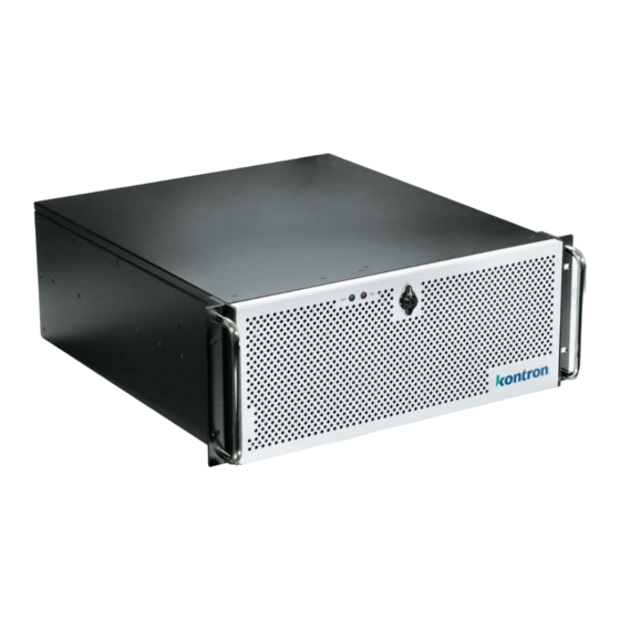
KISS 4U V3 ADL - User Guide, Rev. 1.0 4/ Product Features The KISS 4U V3 ADL expands the Kontron KISS computer line of scalable 4U rackmount systems. The product’s design enables installation in 19" industrial racks or as a desktop. The robust construction with excellent mechanical stability offers the superior qualities of a computer designed for operation in harsh industrial environment. -
Page 23: Front Side
KISS 4U V3 ADL - User Guide, Rev. 1.0 Front Side The front side consists of two handle brackets for installation in a 19” Industrial rack and a front flap with two front flap side-plates attached using the handle brackets. -
Page 24: Front Flap
KISS 4U V3 ADL - User Guide, Rev. 1.0 The power button, LED indicators, two USB 3.2 Gen 1 ports, a filter pad holder and the integrated drives are located on the front side behind the front flap. Figure 8: Front Panel (front flap open) Holder arm for the front flap D2: 5.25"... -
Page 25: Drive Bays
KISS 4U V3 ADL - User Guide, Rev. 1.0 Front flap key must be kept safe and not be accessible to unauthorized persons. If USB devices are connected to the USB ports on the front side, the front flap cannot be closed and locked 4.1.2. -
Page 26: Fan Assembly
KISS 4U V3 ADL - User Guide, Rev. 1.0 4.1.4. Fan Assembly The two system fans are integrated in a user-friendly, replaceable slide-in fan assembly (hot-swap), mounted in a fan compartment on the front side. The two system fans are temperature controlled via temperature sensors, to provide airflow for optimal active cooling. -
Page 27: Filter Pad And Filter Pad Holder
If heavily soiled, the filter pad can cause excessive heating of the product. Kontron recommends cleaning the filter pad as often as necessary, see Chapter 13.3: Cleaning the Filter Pad. -
Page 28: Power Led And Hdd Led
KISS 4U V3 ADL - User Guide, Rev. 1.0 4.1.7. Power LED and HDD LED The LED indicators are located on the front side, behind the front flap. Figure 13: LED Indicators Power LED HDD activity LED Table 3: Power LED and HDD LED Activity... -
Page 29: Rear Panel
KISS 4U V3 ADL - User Guide, Rev. 1.0 Rear Panel The rear panel features the PSU, air exhaust ventilation openings, the external interfaces and PCIe/PCI expansion card interfaces. The PCIe expansion card slot allocation depends on the overall system configuration. -
Page 30: Display Port (Dp)
KISS 4U V3 ADL - User Guide, Rev. 1.0 4.2.1. Display Port (DP) The four Display Ports are DP V1.4a @4K. All DisplayPort outputs are equivalent and compatible with DP++ and support a resolution of 4096x2160 @ 60Hz. The display resolution may vary depends on the number of simultaneous displays. -
Page 31: Audio
KISS 4U V3 ADL - User Guide, Rev. 1.0 The two 2.5 GbE LAN ports feature: i225LM LAN controller IEEE 802.3 specification for 2500BASE-T, 1000BASE-T, 100BASE-Tx, 10BASE-TE TSN support Wake on LAN Link Status change and Magic Packets™... -
Page 32: Power Supply Units
KISS 4U V3 ADL - User Guide, Rev. 1.0 4.2.6. Power Supply Units The Power Supply Unit (PSU) is located on the rear side and supplies the required internal voltages using standard certified cabling. For the PSU power specification, see Table 14: Electrical Specification. -
Page 33: Potential Equalization Stud
KISS 4U V3 ADL - User Guide, Rev. 1.0 The redundant PSU contains two separate PSUs each capable of powering the product alone and each supplied using a dedicated power cable connection to the mains power supply. To ensure the power cables are not accidently removed from the input power sockets, the power connector is held firmly in place by a cable holder. -
Page 34: Pcie/Pci Expansion Card Slots
KISS 4U V3 ADL - User Guide, Rev. 1.0 4.2.8. PCIE/PCI Expansion Card Slots The PCIe/PCI expansion card slots support six PCIe expansion cards and one PCI expansion card. For the PCIE/PCI slot allocation, see Table 9: PCIe/PCI Expansion Card Slots. -
Page 35: Side
KISS 4U V3 ADL - User Guide, Rev. 1.0 Side On the left and right sides are, six M4 tapped screw holes used for installation in a 19" industrial rack with slide rails. Figure 18: Left Side Left side view of a KISS 4U V3 chassis... -
Page 36: Cover
KISS 4U V3 ADL - User Guide, Rev. 1.0 Cover The cover is secures to ensure that operators do not have access to energized internal parts. To open the top cover, see Chapter 7.2: Opening and Closing the Cover. Energy hazards-present inside the chassis! Before removing the top cover, switch off the product properly by using the power button on the front side and disconnecting the power cable(s) from the mains power supply(s). -
Page 37: System Configuration
KISS 4U V3 ADL - User Guide, Rev. 1.0 System Configuration Figure 21: Example of KISS 4U V3 ADL Configuration 19" rack mountable bracket with handle Power supply unit (PSU) Front flap 10. Potential equalization stud Access panel lock 11. External interfaces of the motherboard Cover retaining plate on the front side 12. -
Page 38: 5/ System Expansion
KISS 4U V3 ADL - User Guide, Rev. 1.0 5/ System Expansion This chapter contains important information on how to expand the KISS 4U V3 ADL with storage and expansion cards. Before Expanding Before expanding the product with storage and expansion cards, consider the maximum power consumption allowed by the power supply. -
Page 39: Expansion Cards
PSU is not exceeded. 5.4.1. Reference PCIe Expansion Card The Kontron reference full height PCIe expansion cards support the following functions: Table 10: Reference KISS 4U V3 ADL PCIe Expansion Cards Reference Card Description LAN Dual 1.0 GbE Copper Port... - Page 40 Interface: PCIe 3.0 x16 Form factor: Single slot Power consumption: 40 W Max. simultaneous displays: 4x 3840x2160@120Hz 4x 5120x2880@60Hz 2x 7680x4320@60Hz Others PCIe/PCI expansion card options are available on request. For more information, contact Kontron Support. www.kontron.com // 40...
-
Page 41: 6/ Thermal Management
KISS 4U V3 ADL - User Guide, Rev. 1.0 6/ Thermal Management This chapter contains important information on how to manage KISS 4U V3 ADL thermal considerations. Active Cooling Two system fans within the fan assembly force air to flow through the ventilation holes from the front to the back of the chassis. -
Page 42: Third Party Components
KISS 4U V3 ADL - User Guide, Rev. 1.0 There are no ventilation restrictions above and below the product, enabling installation directly on top of or below another system. Third Party Components When expanding with third party components such as PCIe/PCI expansion cards, M.2 modules, DIMMs and drives (HDD, SSD, DVD);... -
Page 43: 7/ Assembly
7/ Assembly This chapter contains important information on the mechanical assembly and working safely with internal components. Follow these instructions when handling KISS 4U V3 ADL internal components and observe the corresponding safety instruction included in Chapter 2/: General Safety Instructions. -
Page 44: Figure 23: Loosening Knurled Screws (Rear Panel)
KISS 4U V3 ADL - User Guide, Rev. 1.0 Figure 23: Loosening Knurled Screws (rear panel) Pull the cover out slightly as shown in Figure 24 to release the cover’s centering and fixing brackets (Figure 20, pos.3 and pos. 4) from the retaining brackets of the chassis (Figure 21, pos. 4). -
Page 45: Installing And Removing Pcie/Pci Expansion Cards
KISS 4U V3 ADL - User Guide, Rev. 1.0 Installing and Removing PCIe/PCI Expansion Cards Consult the documentation provided by the expansion card’s manufacturer for instructions before installing/removing the expansion card. Insert a blank slot bracket into an empty expansion card slot and secure with screw The PCIe/PCI expansion cards are secured on the rear side and internally using the internal long and short brackets with PCB holder (Figure 26). -
Page 46: Figure 27: Steps To Remove/Install The Short And Long Brackets
KISS 4U V3 ADL - User Guide, Rev. 1.0 Pull the short bracket to the left (Figure 27, step 3) to detach the short bracket from the sideways mounted bolts. Lift the short bracket out of the chassis (Figure 27, step 4) and retain for later use with screws. -
Page 47: Installing And Removing The Handle Brackets
KISS 4U V3 ADL - User Guide, Rev. 1.0 To keep expansion card firmly in place during high mechanical load (shock and vibrations) PCB holders (Figure 26) are used to stabilize the expansion cards (especially long expansion cards). To install or remove a PCB holder: Fix the upper edge of the expansion card (especially with long expansion cards) into the required notch of the PCB holder (Figure 26, pos. -
Page 48: Installing And Removing The Front Flap
KISS 4U V3 ADL - User Guide, Rev. 1.0 Installing and Removing the Front Flap The front flap and the two front flap side-plates are removable. Figure 29: Front Flap Side-plate (left and right) Front flat side-plate (left and right) To remove the front flap and the two front flap side-plates, proceed as follows: Remove the handle brackets as described in Chapter 7.4: Removing the Handle Brackets (steps 1-2) and retain the... -
Page 49: Installing Slide Rails (Option)
KISS 4U V3 ADL - User Guide, Rev. 1.0 Installing Slide Rails (option) Kontron offers a 19” Slide Rails and Rack Slide Rails Kit. For more information, see Table 2: Accessories and Spares Parts. To support the products weight, two separate fixation methods must be used: •... -
Page 50: Figure 32: Slide Rail In Pushed-In Position
KISS 4U V3 ADL - User Guide, Rev. 1.0 Figure 32: Slide Rail in Pushed-in Position Figure 33: Assembling the Slide Rails in an Industrial Rack Cabinet Short front rack bracket Telescopic slide rail attached to Industrial rack cabinet Long rear rack bracket Short rack brackets are used at the front of the chassis and long rack brackets at the rear. -
Page 51: 8/ Installation
KISS 4U V3 ADL - User Guide, Rev. 1.0 8/ Installation This chapter contains important information on how to mount the KISS 4U V3 ADL in a 19” Industrial rack and in customer specific environments. Before Installing Before installing the product, read the installation instructions within this chapter and observe the information in Chapter2/General Safety Instructions. -
Page 52: Installing As A Desktop
KISS 4U V3 ADL - User Guide, Rev. 1.0 Installing as a Desktop Before installing the product in a desktop environment, install the delivered rubber feet, to avoid scratching the installation surface. Additionally, observe the general instructions and any safety warnings within this chapter. - Page 53 KISS 4U V3 ADL - User Guide, Rev. 1.0 Installing the product alone can result in product damage or personal injury. Due to possible access restrictions, before installing the product install all expansion card and connect required peripherals to the corresponding system ports.
-
Page 54: 9/ Starting Up
KISS 4U V3 ADL - User Guide, Rev. 1.0 9/ Starting Up This chapter contains important information on how to connect to a power supply and start the KISS 4U V3 ADL. Before Starting Before staring up observe the instructions within this chapter and refer to Chapter 2/ General Safety Instructions. -
Page 55: Connecting To The Redundant Power Supply (Option)
KISS 4U V3 ADL - User Guide, Rev. 1.0 To connect the power, proceed as follows: Connect the ends of the supplied AC power cable (with the correct electrical plug for your region) to the Input power socket (Figure 34, pos. 1) and the mains power supply socket using the electrical plug for the region. -
Page 56: Switching On
If ordered without pre-installed OS, before starting the product install the OS and the appropriate drivers for the system configuration. Consider the manufacturer’s specifications for the OS and the integrated hardware components. To download relevant drivers for the installed hardware, visit Kontron’s Customer Section Website. Pay attention to the installed hardware components manufacturer’s OS specification. -
Page 57: 10/ Bios
KISS 4U V3 ADL - User Guide, Rev. 1.0 BIOS The KISS 4U V3 ADL uses the uEFI BIOS supported by the motherboard. This chapter informs user how to start, setup, navigate, update and recover the BIOS. uEFI only! No legacy support and no Master Boot Record (MBR) installation. -
Page 58: Bios Navigation
The latest BIOS updates and BIOS release information for the product is available by accessing the Motherboard FTP server on Kontron’s Customer Section Website by selecting Motherboards & SBC > ATX > K3851-R ATX > Link to the FTP Server. The FTP server provides operators with downloads of the latest BIOS version and general BIOS information. -
Page 59: Recover Bios
KISS 4U V3 ADL - User Guide, Rev. 1.0 For the latest BIOS updates and BIOS release information, visit Kontron’s Customer Section Website and select: Motherboards & SBC > ATX > K3851-R ATX > Link to the FTP Server. 10.5.1. -
Page 60: 11/ Product Specifications
KISS 4U V3 ADL - User Guide, Rev. 1.0 11/ Product Specifications The chapter describes the technical specifications of the KISS 4U V3 ADL. Block Diagrams Figure 38: Block Diagram KISS 4U V3 ADL KISS 4U V3 ADL ATX Mainboard Intel®... -
Page 61: Hardware Specification
KISS 4U V3 ADL - User Guide, Rev. 1.0 Hardware Specification Table 12: Hardware Specification KISS 4U V3 ADL Motherboard Type K3851-R ATX Processor Type Intel® 12 /13th Gen Core™, i9, i7, i5 und i3 Processors Processor Cores Base Frequency... -
Page 62: Software Specification
KISS 4U V3 ADL - User Guide, Rev. 1.0 Expansion Slots PCIe/PCI cards Slot 1: 1x PCIe x16, Gen 5, 16 lanes (full-height, full-length) Slot 2: 1x PCIe x1, Gen 3 (open) Slot 3:1x PCIe x16, Gen 4, 4 lane... -
Page 63: Environmental Specification
KISS 4U V3 ADL - User Guide, Rev. 1.0 Easy Access to Power Cable and Power Connectors The power cable must always remain easily accessible. If the end environment restricts access to power cable, disconnection must be guaranteed using a separate cut-off fixture. -
Page 64: Mechanical Specification
For detailed mechanical dimensions, visit Kontron’s Customer Section Website. Compliance The KISS 4U V3 ADL plans to comply with the relevant requirements and the approximation of the laws relating to the CE Mark and the standards that are constitutional parts of the declaration. -
Page 65: Table 18: International Compliance
Kontron is not responsible for any radio television interference caused by unauthorized modifications of the delivered product or the substitution or attachment of connecting cables and equipment other than those specified by Kontron. The correction of interference caused by unauthorized modification, substitution or attachment is the user’s responsibility. -
Page 66: 12/ Standard Interfaces- Pin Assignments
KISS 4U V3 ADL - User Guide, Rev. 1.0 Standard Interfaces- Pin Assignments DP Port Pin Assignment Table 19: DP V1.4a Pin Assignment Signal Name Signal Name DPP (V1.4) Connector Link0+ Link0- Link1+ Link1- Link2+ Link2- Link3+ Link3- DVI dongle detect... -
Page 67: Usb-C 3.2 Gen 2 Port Pin Assignment
KISS 4U V3 ADL - User Guide, Rev. 1.0 USB-C 3.2 Gen 2 Port Pin Assignment Table 21: USB 3.2 Gen 2 Type C Pin Assignment Pin-A Signal Name Pin-B Signal Name USB 3.2 Gen 2-C Type Connector USB3_TX1+ USB3_RX+... -
Page 68: Com Port Pin Assignment
KISS 4U V3 ADL - User Guide, Rev. 1.0 LAN Cabling 1000Base-T CAT 5E/6 or higher up to 100m 100Base-T CAT 5/5E/6 or higher up to 100m 10Base-T CAT 3/4/5/5E/6 or higher up to 100m COM Port Pin Assignment Table 23: RS232 Connector Pin Assignment... -
Page 69: M.2 Key M (Nvme Ssd) Socket Pin Assignment
KISS 4U V3 ADL - User Guide, Rev. 1.0 M.2 Key M (NVME SSD) Socket Pin Assignment Table 25: M.2 Key M Socket Pin Assignment Signal Name Signal Name M.2 Key M +3.3V +3.3V PCIe RX 3- PCIe RX 3+... -
Page 70: Jumpers
KISS 4U V3 ADL - User Guide, Rev. 1.0 Jumpers 12.8.1. Recover BIOS Jumper The recover BIOS Jumper is located on the motherboard’s front panel header. To recover the BIOS, move the recover BIOS jumper from the default position (Figure 39, pos. 1) to the recover BIOS position (Figure 39, pos. 2) on the front panel header. -
Page 71: 13/ Maintenance And Prevention
Maintenance and Prevention Maintenance or repair may only be carried out by Kontron authorized qualified personnel. The KISS 4U V3-ADL only require minimal maintenance and care to keep them operating correctly. Clean the air filter pad regularly (as often as necessary, the time-period will depend on the level of contaminates with in the operating environment. -
Page 72: Figure 40: Front Side With Filter Pad Holder
KISS 4U V3 ADL - User Guide, Rev. 1.0 Figure 40: Front Side with Filter Pad Holder Front side Front asses panel Filter pad Fan assembly Filter pad holder with knurled screw Fan assembly’s two knurled screws To replace the filter pad, proceed as follows: Open the front flap (Figure 40, pos. -
Page 73: Replacing The Fan Assembly
KISS 4U V3 ADL - User Guide, Rev. 1.0 Figure 41: Fan Assemble without Filter Pad Holder Figure 42: Filter Pad Holder (without Figure 43: Filter Pad Holder (with Figure 44: Filter Pad filter pad) filter pad) Legend for Figure 41, Figure 42. Figure 43 and Figure 44... -
Page 74: Figure 45: Removing The Fan Assembly
KISS 4U V3 ADL - User Guide, Rev. 1.0 The fan assembly simplifies the installation and removal of the two system fans, and is hot- swappable, enabling the replacement of the fans even during operation. No tools are required to replace the system fans. -
Page 75: Replacing The Faulty Redundant Psu
KISS 4U V3 ADL - User Guide, Rev. 1.0 Replacing the Faulty Redundant PSU If one of the PSUs fails, the faulty PSU shuts down and the indication LED changes color from green (active) to red (faulty). The functional PSU takes over the full operation of the product until the faulty PSU is replaced. -
Page 76: Replacing The Lithium Battery
Replaced the lithium battery only with the same type of battery or with a type of battery recommended by Kontron. To replace the factory installed lithium battery (CR2032) on the motherboard, perform the following: Switch off and disconnect the product from the mains power supply. - Page 77 KISS 4U V3 ADL - User Guide, Rev. 1.0 To replace or exchange a factory installed M.2 SSD module, perform the following: Switch off and disconnect the product properly from the mains power supply. Open the cover, see Chapter 7.2: Opening and Closing the Cover.
-
Page 78: 14/ Storage And Transportation
The storage facility must meet the products environmental storage requirements as stated within this user guide. Kontron recommends keeping the original packaging material for future storage or warranty shipments. -
Page 79: 15/ Technical Support
RMA number. The buyer accepts responsibility for all freight charges for the return of goods to Kontron's designated facility. Kontron will pay the return freight charges back to the buyer's location in the event that the equipment is repaired or replaced within the stipulated warranty period. - Page 80 86156 Augsburg Germany Phone: +49 (0) 821 4086-0 Fax: +49 (0) 821 4086 111 Email: service@kontron.com After receiving the product, Kontron Europe GmbH sends a confirmation of the order to the email address named on the RMA sheet. www.kontron.com // 80...
-
Page 81: 16/ Warranty
Limitation/Exemption from Warranty Obligation In general, Kontron shall not be required to honor the warranty, even during the warranty period, and shall be exempted from the statutory accident liability obligations in the event of damage caused to the product due to failure to observe the following: ... -
Page 82: Appendix: List Of Acronyms
KISS 4U V3 ADL - User Guide, Rev. 1.0 Appendix: List of Acronyms Table 27: List of Acronyms Active Management Technology PICMG® PCI Industrial Computer Manufacturers Group Advanced Technology eXtended Power Supply Unit BIOS Basic Input Output System Preboot Execution Environment... -
Page 83: About Kontron
KISS 4U V3 ADL – User Guide, Rev. 1.0 About Kontron Kontron is a global leader in IoT/Embedded Computing Technology (ECT). Kontron offers individual solutions in the areas of Internet of Things (IoT) and Industry 4.0 through a combined portfolio of hardware, software and services.
Need help?
Do you have a question about the KISS 4U V3 ADL and is the answer not in the manual?
Questions and answers