
Related Manuals for Kontron KISS 4U Short V2 Series


Summary of Contents for Kontron KISS 4U Short V2 Series
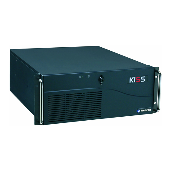
- Page 1 KISS 4U Short V2 User's Guide (Version 1.00) 0-0096-6849 If it’s embedded, it’s Kontron.
- Page 2 This page is intentionally left blank. www.kontron.com...
-
Page 3: Table Of Contents
7.3. Fan Slide-in Module and Temperature Sensor....................23 7.4. Accessing Internal Components .......................24 7.4.1. Installing/Removing the Expansion Cards ...................24 7.5. Installation in a 19" Industrial Cabinet .....................27 8. Starting Up ............................28 8.1. Power Cord Connection...........................28 8.2. Operating System and Hardware Component Drivers ..................29 www.kontron.com... -
Page 4: Table Of Figures
Fig. 15: KISS 4U Short V2 platform – side view ....................21 Fig. 16: Inside of the cover with fixing brackets ....................22 Fig. 17: Fan slide-in module ..........................23 Fig. 18: Lösen der Deckel-Anziehschraube an der Frontseite................24 Fig. 19: Lösen der Rändelschrauben an der Rückseite..................24 www.kontron.com... - Page 5 Fig. 31: Detail: Fan compartment (without fan slide-in module) ................32 Fig. 32: Inner sider of the fan slide-in module....................33 Fig. 33: Fan slide-in module with inserted filter mat..................33 Fig. 34: Location of the Lithium Battery ......................34 www.kontron.com...
-
Page 6: Introduction
Kontron Embedded Computers is aware of such errors or inaccuracies or that Kontron Embedded Computers is unaware of these as a result of gross negligence and Kontron Embedded Computers has failed to eliminate these errors or inaccuracies for this reason. Kontron Embedded Computers expressly informs the user that this manual only contains a general description of technical processes and instructions which may not be applicable in every individual case. -
Page 7: Symbols Used In This Manual
This symbol indicates that the product or parts thereof may be damaged if the corresponding warning notices are not observed. This symbol indicates general information about the product and the user manual. This symbol indicates detail information about the specific product configuration. This symbol precedes helpful hints and tips for daily use. www.kontron.com... -
Page 8: Important Instructions
In the event of damage to the device caused by failure to observe the included document “General Safety Instructions for IT Equipment”, the hints in this manual or eventually the warning signs label on the device, Kontron Embedded Computers shall not be required to honor the warranty even during the warranty period and shall be exempted from the statutory accident liability obligation. -
Page 9: Safety Instructions
If the enclosure of such a drive is opened, invisible laser radiation is emitted. Do not allow yourself to be exposed to this radiation. The laser system meets the code of Federal Regulations 21 CFR, 1040 for the USA and the Canadian Radiation Emitting Devices Act, REDR C 1370. www.kontron.com... -
Page 10: Electrostatic Discharge (Esd)
The lithium battery type must be UL recognized. Do not dispose of lithium batteries in general trash collection. Dispose of the battery according to the local regulations dealing with the disposal of these special materials, (e.g. to the collecting points for dispose of batteries). www.kontron.com... -
Page 11: Fcc Statement
CE conformity declaration (safety requirements) may no longer apply. Warning! This is a class A product. In domestic environment this product may cause radio interference in which case the user may be required to take adequate measures. www.kontron.com... -
Page 12: Scope Of Delivery
KISS 4U Short V2 = System type The “xxx”-Group is replaced by two-digit or three-digit figures, representing the installed CPU board. “y” is replaced by a single letter (A through Z) representing the power supply installed in the system. www.kontron.com... -
Page 13: Product Description
6. Product Description The KISS 4U Short V2 platform expands the Kontron KISS computer line. KISS 4U Short V2 is a scalable 4U (19") platform, that is equipped with a motherboard, supporting various system configurations (refer to “KISS 4U Short V2 System - Configuration Guide”... - Page 14 The type label is attached to the right side of the device. The KISS 4U Short V2 platform may be operated in horizontal position only. When powering on the KISS 4U Short V2 platform, make sure that the air intake and exhaust openings are not obstructed by objects. www.kontron.com...
- Page 15 14 Fastening screw for the card hold down bracket (internal accessible) 6 L1, L2 and L3: Drives (mounted on top of each other in a drive cage) 15 Fan compartment 7 Mounting bracket for the card hold down bracket 8 AC power supply unit www.kontron.com...
-
Page 16: Front Side
The KISS 4U Short V2 platform will be delivered as rackmount version. Fig. 7: Front side (rackmount version) with closed front access door 1 19" handle bracket 4 Kontron Logo 2 Holes for mounting in 19" racks 5 Securing lock mechanism... - Page 17 13 Cover fastening screw on the front side 7 L2: front accessible 5.25"drive bay (shown with a 14 LED Indicators (Power LED, HDD activity LED) KISS DA 135) 15 Filter mat and filter mat holder with knurled screw www.kontron.com...
-
Page 18: Interfaces On The Front Side
Please observe the option in BIOS Setup / Chipset Configuration / South Bridge Configuration / Restore on AC Power Loss with the option settings: Power On/ Power Off/Last State. Standard configuration of KISS 4U Short V2 platform is delivered with the default setting “Power On”. www.kontron.com... -
Page 19: Front Access Door
(Fig. 27, pos. 5) and two positioning latches (Fig. 27, pos. 6). A filter mat is inserted in the filter mat holder (refer to Fig. 28 and Fig. 29). This filter mat protects your system against dust and dirt (see chapter 9.1 “Cleaning the Filter Mat”). www.kontron.com... -
Page 20: Fan Slide-In Module
L1, L2 and are occupied by this subsystem with removable HDDs. For customer-specific versions and system configurations, please refer to the corresponding “KISS 4U Short V2 System - Configuration Guide” for KISS 4U Short V2 on our website www.kontron.com. www.kontron.com... -
Page 21: Rear Side
The positioning and number of the KISS 4U Short V2 platform interfaces may vary depending on the system configuration. Information and technical data can be found in the corresponding board manual of the installed motherboard. You can download the relevant board manual for your system from our web site at www.kontron.com selecting the product name. www.kontron.com... -
Page 22: Power Supply Unit And Psu Switch
EASY 485/422 module (refer to Fig. 12, pos. 10). You can connect peripheral devices to these connectors. You can download the relevant CPU card manual for your system configuration from our web site at www.kontron.com by selecting the product. See also “KISS 4U Short V2 System - Configuration Guide” on our website. -
Page 23: Side View
M3x6) for fastening the card hold down bracket for 2 4x M4 tapped holes (on both sides) long expansion cards 3 Cover with captive knurled screws (for 5 Internal bolt for the card hold down bracket for securing the cover to the chassis) expansion cards www.kontron.com... -
Page 24: Assembly, Disassembly
4 Fixing latch (on the front side) 2 Front part of the cover 5 Rear part of the cover 3 Angulated centering latch with tapped 6 Fixing latches with knurled screws (on the hole (on the front side) rear side) www.kontron.com... -
Page 25: Fan Slide-In Module And Temperature Sensor
4 Bracket of the fan slide-in module The operation of the KISS 4U Short V2 platform is permitted only with a functional fan slide-in module! Defective components may only be replaced by Kontron original spare parts. “fan slide-in module”, part number: 1035-6968 Important Instructions! The fan slide-in module can be replaced during operation. -
Page 26: Accessing Internal Components
2. Loosen the knurled screws (the cover fastening screw on the front side and the two knurled screws on the rear side) which secure the cover (see Fig. 18 and Fig. 19). Fig. 18: Lösen der Deckel-Anziehschraube an der Frontseite Fig. 19: Lösen der Rändelschrauben an der Rückseite www.kontron.com... - Page 27 2 Holes for the internal bolts (Fig. 15, Pos. 5) 3 Notches for the fastening screws that secure the card hold down brackets to the internal mounting bracket (Fig. 6, pos 7) Fig. 22: Card hold down bracket for long expansion cards www.kontron.com...
- Page 28 The chassis of the KISS 4U Short V2 platform with attached cover is properly closed only, if the following knurled screws are tightened: the cover fastening screw (Fig. 9, pos. 13 and Fig. 18) on the front side the knurled screws (Fig. 12, pos. 8 and Fig. 19)on the rear side. www.kontron.com...
-
Page 29: Installation In A 19" Industrial Cabinet
If further stabilization is necessary, then bolt the 19" industrial cabinet to the floor or anchor it on the wall. The voltage feeds must not be overloaded. Adjust the cabling and the external overcharge protection to correspond with the electrical data indicated on the type label. The type label is located on right side of the unit. www.kontron.com... -
Page 30: Starting Up
3. Connect the other end of the AC power cord to a corresponding mains power source outlet. Make sure that the power supply (power outlet) is properly grounded and that the power cord is in perfect condition without any visible damage. An ungrounded power supply is not permissible. www.kontron.com... -
Page 31: Operating System And Hardware Component Drivers
(optional hardware components) yourself. You can download the relevant drivers for the installed hardware from our web site at www.kontron.com by selecting the product. Consider the manufacturer’s specifications for the operating system and the integrated hardware components. -
Page 32: Maintenance And Prevention
KISS 4U Short V2 – User's Guide (Version 1.00) 9. Maintenance and Prevention Equipment from Kontron Embedded Computers requires only minimum servicing and maintenance for problem-free operation. For light soiling, clean the KISS 4U Short V2 with a dry cloth. - Page 33 8. Fix the filter mat holder by tightening the knurled screw (Fig. 27, pos. 5) to the bolt with tapped hole (Fig. 26, pos. 1) at the fan slide-in module. Defective components may only be replaced by Kontron original spare parts. Air filter mat: part number: 1035-6957.
-
Page 34: Replacing The System Fans
9.2. Replacing the System Fans The operation of the KISS 4U Short V2 system is permitted only with a functional fan slide-in module! Defective components may only be replaced by Kontron original spare parts. part number of the fan slide-in module: 1035-6968 The fan slide-in module can be replaced during operation. - Page 35 Install the filter mat holder (put aside in step 1) with the filter mat to the front side of the fan slide- in module, as described in chapter 9.1 “Cleaning the Filter Mat” (step 7 and step 8). www.kontron.com...
-
Page 36: Replacing The Lithium Battery
5. Pay attention to the polarity of the battery; refer to Fig. 34. 6. The lithium battery must be replaced with an identical battery or a battery type recommended by Kontron Embedded Computers (Lithium battery 3.0 V for RTC, type: CR2032). -
Page 37: Technical Data
“y” is replaced by a single letter (A through Z) representing the power supply installed in the system. The corresponding “KISS 4U Short V2 Systems - Configuration Guides” and the manual of the installed board can be downloaded from our web site at www.kontron.com by selecting the product name. 10.1. Electrical Specifications The electrical specifications of your KISS 4U Short V2 platform can be found on the type label. -
Page 38: Mechanical Specifications
15 G, 11 ms, half sine Storage/Transit Shock 30 G., 11 ms, half sine Operating Vibration 10 – 500 Hz, 1.0 G Storage/Transit Vibration 10 – 500 Hz, 2.0 G Acoustic Noise < 35 dB(A) at 1 m in front of the system www.kontron.com... -
Page 39: Ce Directives And Standards
UL60950-1:2007 / CSA C22.2- No. 60950-1-7:2007 Harmonized Standards Generic emission standard for industrial environments (Emission): EN 61000-6-4:2007 Generic standards - Immunity for industrial environments (Immunity): EN 61000-6-2:2005 U.S.A. FCC 47 CFR Part 15, Class A CANADA ICES-003, Class A www.kontron.com... -
Page 40: Standard Interfaces - Pin Assignments
(Request to Send) (Clear to Send) (Ring Indicator) 11.2. VGA Port Signal Name 15-pin D-SUB Connector (female) Analog red output Analog green output Analog blue output N.C. +5 V (DDC) N.C. SDA (DDC) TTL HSync TTL VSync SCL (DDC) www.kontron.com... -
Page 41: Usb Port
Type A Version 2.0 Data- Data+ 11.4. PS/2 Keyboard Connector Signal Name 6-pin Mini-DIN Connector Keyboard Data N.C. +5 V Keyboard Clock V.C. 11.5. PS/2 Mouse Connector Signal Name 6-pin Mini-DIN Connector Mouse Data N.C. +5 V Mouse Clock N.C. www.kontron.com... -
Page 42: Technical Support
• the serial number (SN) of the unit; the serial number can be found on the type label, placed on the right side of the system. Be ready to explain the nature of your problem to the service technician. If you have questions about Kontron Embedded Computers or our products and services, you may reach us at the aforementioned numbers, or at: www.kontron.com...
Need help?
Do you have a question about the KISS 4U Short V2 Series and is the answer not in the manual?
Questions and answers