Table of Contents
Advertisement
Quick Links
Advertisement
Table of Contents

Related Manuals for Kontron KISS 1U V4 ADL


Summary of Contents for Kontron KISS 1U V4 ADL
- Page 1 User Guide KISS 1U V4 ADL User Guide Rev. 1.0 Doc. ID 1073-6888 www.kontron.com...
- Page 2 KISS 1U V4 ADL – User Guide Rev. 1.0 This page has been intentionally left blank // 2 www.kontron.com...
- Page 3 Kontron would like to point out that the information contained in this user guide may be subject to alteration, particularly as a result of the constant upgrading of Kontron products. This document does not entail any guarantee on the part of Kontron with respect to technical processes described in the user guide or any product characteristics set out in the user guide.
- Page 4 (collectively, “high risk applications”). You understand and agree that your use of Kontron devices as a component in High Risk Applications is entirely at your risk. To minimize the risks associated with your products and applications, you should provide adequate design and operating safeguards.
- Page 5 Kontron sells products worldwide and declares regional General Terms & Conditions of Sale, and Purchase Order Terms & Conditions. Visit www.kontron.com/terms-and-conditions. For contact information, refer to the corporate offices contact information on the last page of this user guide or visit...
-
Page 6: Symbols
KISS 1U V4 ADL – User Guide Rev. 1.0 Symbols The following symbols may be used in this user guide DANGER indicates a hazardous situation which, if not avoided, will result in death or serious injury. WARNING indicates a hazardous situation which, if not avoided, could result in death or serious injury. -
Page 7: For Your Safety
Therefore, in the interest of your own safety and of the correct operation of your new Kontron product, you are requested to conform with the following guidelines. -
Page 8: Lithium Battery Precautions
General Instructions on Usage In order to maintain Kontron’s product warranty, this product must not be altered or modified in any way. Changes or modifications to the product, that are not explicitly approved by Kontron and described in this user guide or received from Kontron Support as a special handling instruction, will void your warranty. -
Page 9: Table Of Contents
KISS 1U V4 ADL – User Guide Rev. 1.0 Table of Contents Symbols ..................................6 For Your Safety ................................7 High Voltage Safety Instructions ........................... 7 Special Handling and Unpacking Instruction ......................7 Lithium Battery Precautions ..........................8 General Instructions on Usage ............................8 Quality and Environmental Management ........................ -
Page 10: List Of Tables
KISS 1U V4 ADL – User Guide Rev. 1.0 8.1. Before Mounting ............................40 8.2. Mounting in a 19” Industrial Rack Cabinet ....................41 8.3. Mounting on a Desktop ..........................42 Starting Up................................43 9.1. Before Starting ............................. 43 9.2. Connecting the Power Supply ........................43 9.3. -
Page 11: List Of Figures
Figure 9: Sides (left and right) ............................. 26 Figure 10: Cover Underside ............................27 Figure 11: KISS 1U V4 ADL System Configuration ....................... 28 Figure 12: Rear Panel Knurled Screws ......................... 34 Figure 13: Pull and Release the Cover ......................... 34 Figure 14: Removing the Cover ........................... - Page 12 KISS 1U V4 ADL – User Guide Rev. 1.0 Figure 31: Recover BIOS Jumper (in default position)....................56 Figure 32: Filter Door with Pad (front and rear side) ....................58 Figure 33: Filter Door (dismantled) ..........................58 Figure 34: System Fans Internal Assembly ........................59 Figure 35: Vertical Battery Holder ..........................
-
Page 13: 1/ Introduction
1/ Introduction This user guide focuses on describing the special features of the KISS 1U V4 ADL made by Kontron and referred to as product within this user guide. The KISS 1U V4 ADL expands the Kontron KISS computer line. Kontron recommends operators to study the instructions within this user guide before switching on the power. -
Page 14: 2/ General Safety Instructions
Only connect the product to an external power supply providing the voltage type (AC or DC) and the input power (max. current) specified on the Kontron Product Label and meeting the requirements of the Limited Power Source (LPS) and Power Source (PS2) of UL/IEC 62368-1 . -
Page 15: Instructions Générales De Sécurité
Le non-respect des consignes de sécurité générales suivantes peut entraîner des blessures pour l'utilisateur et/ou des dommages pour le produit. En cas de non-respect des consignes, Kontron Europe est exonéré de la responsabilité en cas d'accident, ceci s'applique également pendant la période de garantie. -
Page 16: Electrostatic Discharge (Esd)
KISS 1U V4 ADL – User Guide Rev. 1.0 le produit présente des dommages visibles ou le produit ne fonctionne plus. Dans ce cas, le produit doit être éteint et il faut s'assurer que le produit ne puisse plus être utilisé. -
Page 17: Instructions For Lithium Battery
KISS 1U V4 ADL – User Guide Rev. 1.0 2.4. Instructions for Lithium Battery The product is equipped with a lithium battery, there is a risk of explosion if the lithium battery is replaced incorrectly (short-circuited, reverse-poled, wrong lithium battery type). -
Page 18: 3/ Shipment And Unpacking
KISS 1U V4 ADL – User Guide Rev. 1.0 3/ Shipment and Unpacking 3.1. Packaging The KISS 1U V4 ADL is packaged together with all parts, in a product specific cardboard package designed to provide adequate protection and absorb shock. 3.2. Unpacking To unpack the product perform the following: 1. -
Page 19: Product Identification Type Label
KISS 1U V4 ADL – User Guide Rev. 1.0 3.5. Product Identification Type Label The type label includes important information such as the electrical specification data for the ordered configuration. Figure 2: Type Label (example) KISS 1U V4 ADL 2-A0JT-0000 1. -
Page 20: 4/ Product Features
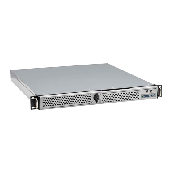
KISS 1U V4 ADL – User Guide Rev. 1.0 4/ Product Features 4.1. Front Features The front panel features two removable handle brackets for installation in a 19” industrial rack and an optional front flap with key lock, and power and HDD activity LEDs. -
Page 21: Front Flap (Option)
KISS 1U V4 ADL – User Guide Rev. 1.0 4.1.1. Front Flap (option) The optional front flap (Figure 4, pos. 2) is installed on the front panel. The front flap’s lock mechanism protects against unauthorized use. When locked the front flap cannot be opened without a key, and items on the front panel are not accessible. -
Page 22: System Fan Assembly
Operation is permitted only with a functional fan assembly! Only replace a defective system fan assembly with an original Kontron system fan assembly, see Table 2: Accessories and Spare Parts. The system fan assembly is not replaceable during operation. -
Page 23: Power Led And Hdd Activity Led
KISS 1U V4 ADL – User Guide Rev. 1.0 Forces Shutdown Switch off using the power button to perform an orderly shutdown without data loss. Do not disconnect the power from the product while the product is switched on! Performing a forced shutdown can lead to loss of data or other undesirable effects! 4.1.7. -
Page 24: Rear Panel
KISS 1U V4 ADL – User Guide Rev. 1.0 4.2. Rear Panel The rear panel includes the external interfaces, one PCIe x16 expansion card slot for full-height, full-length) PCIe cards, input power socket, potential equalization stud and three knurled screws to secure the cover. -
Page 25: Input Power
KISS 1U V4 ADL – User Guide Rev. 1.0 Kontron is not responsible for problems occurring after the installation of PCIe expansion card(s) that have not been factory installed and configured by Kontron. Before extending the product with a PCIe expansion card, consider the maximum power consumption allowed for by the product’s PSU. -
Page 26: Sides (Left And Right)
KISS 1U V4 ADL – User Guide Rev. 1.0 4.3. Sides (Left and Right) The left and right sides both include three M4 threaded screw holes for the installation of a telescopic slide rail to mount the product in a 19" industrial rack cabinet. The left and right sides both include a factory installed handle bracket to secure the product to the front posts of a 19”... -
Page 27: Cover
KISS 1U V4 ADL – User Guide Rev. 1.0 4.4. Cover The cover fixes to the product’s main chassis using three fixing brackets on the front side of the cover and three knurled screws on the cover’s rear side. When closing the cover, the cover’s front side fixing brackets insert into the corresponding retaining brackets on the product’s main chassis and secures using the three knurled screws on the... -
Page 28: System Configuration
KISS 1U V4 ADL – User Guide Rev. 1.0 4.5. System Configuration The internal system configuration includes the following items that the operator may be required to access mini-ITX motherboard with on-board SODIMMs and M.2 2242 SSD, fan assembly with two system fans, internal 2.5” SSD drive, PCIE x16 slot for PCIe expansion cards (full-height, full-length) and internal drive bay internal 3.5”... -
Page 29: 5/ System Extension
KISS 1U V4 ADL – User Guide Rev. 1.0 5/ System Extension Due to the limited lifespan of expansion devices, Kontron recommends checking the condition of any installed expansion devices regularly and to pay attention to the manufacturer’s lifespan specifications. -
Page 30: Reference Expansion Cards
Before expanding the product with a PCIe expansion card users must consider the product’s maximum allowed power consumption and take cooling into consideration. The PCIe expansion slot supports one PCIe x16 (full-height, full-length) card. Kontron installs and configures the product with an ordered reference PCIe expansion card, including all appropriate drivers. Kontron is not responsible for problems occurring after the installation of a PCIe expansion card that has not been factory installation and configured by Kontron. -
Page 31: 6/ Thermal Consideration
6.1. Active Cooling The KISS 1U V4 ADL is forced air-cooled using a fan assembly with two internal system fans that force air to flow from the front to the back of the product. The processor and extension cards have integrated cooling solutions or are equipped with the corresponding cooling devices. -
Page 32: Third Party Components
KISS 1U V4 ADL – User Guide Rev. 1.0 6.5. Third Party Components If configured with third party components such as a PCIe expansion card, M.2 module, SODIMMs and hard drive(s) (3.5” HDD, or 2.5” SSD), there is an internal temperature rise. Thus, the air temperature inside the product is higher than the ambient air temperature around the product. -
Page 33: 7/ Assembly
7/ Assembly This chapter contains important information on the mechanical assembly and working safely with internal components. Follow these instructions when handling KISS 1U V4 ADL internal components and observe the corresponding safety instruction included in Chapter 2/: General Safety Instructions. -
Page 34: Installing And Removing A Pcie Expansion Card
KISS 1U V4 ADL – User Guide Rev. 1.0 To access internal components, open the cover. To open the cover, proceed as follows: 1. Switch off properly using the power button and disconnect the power cable from the mains power supply or the input power socket. -
Page 35: Installing And Removing The Handle Brackets
KISS 1U V4 ADL – User Guide Rev. 1.0 3. Remove the slot bracket screw (Figure 15, pos. 3). Retain the screw for later use. 4. Loosen the slide bracket screw (Figure 15, pos. 4) but do not remove the screw. -
Page 36: Installing Or Removing The Front Flap
KISS 1U V4 ADL – User Guide Rev. 1.0 Figure 16: Handle Bracket 1. 1x Handle bracket 2. 2x Handle bracket screws 7.5. Installing or Removing the Front Flap If the front flap plate and handle brackets are both installed, position the front flap plate between the chassis and the handle bracket. -
Page 37: Installing The Rubber Feet
KISS 1U V4 ADL – User Guide Rev. 1.0 3. Install the lock mechanism to the front panel with the two screws provided (Figure 19, pos. 2). 4. Position the plastic washer on the arm of the locking mechanism (Figure 19, pos. 4) Figure 19: Front Flap Locking Mechanism 1. -
Page 38: Installing Slide Rails
5. Return the product to the upwards position (cover facing upward). 7.7. Installing Slide Rails Kontron offers compatible 19” Slide Rails with a mounting kit for the KISS 1U V4 ADL. For more information, see Table 2: Accessories and Spare Parts. -
Page 39: Figure 22: Installed Inner Slide Rail
KISS 1U V4 ADL – User Guide Rev. 1.0 Figure 22: Installed Inner Slide Rail 1. 3 Screws 2. Inner slide rail part // 39 www.kontron.com... -
Page 40: 8/ Mounting
KISS 1U V4 ADL – User Guide Rev. 1.0 8/ Mounting This chapter contains important information on how to mount the KISS 1U V4 ADL in a 19” Industrial rack and in customer specific environments. 8.1. Before Mounting Before mounting the KISS 1U V4 ADL in a 19” industrial rack cabinet or desktop environment read the instructions in this chapter and observe the information in Chapter 2/General Safety Instructions. -
Page 41: Mounting In A 19" Industrial Rack Cabinet
KISS 1U V4 ADL – User Guide Rev. 1.0 8.2. Mounting in a 19” Industrial Rack Cabinet The product is designed for horizontal installation in a 19” industrial rack cabinet (four-post rack) with the top cover facing upwards. Vertical operation is not permitted. Ensure the 19” industrial rack cabinet is well ventilated and does not prevent the product from drawing in air at the front and exhausting air at the rear. -
Page 42: Mounting On A Desktop
2. Attach the inner slide rails to the product, see Chapter 7.7: Installing Slide Rails. 3. Attach the Rack Mount Brackets (from Kontron’s slide Rail kit) to the left and right front and rear posts of the 19” industrial rack cabinet using the supplied four plates and 4 screws M6x10. Ensure that the Rack Mount Brackets are mounted in the same vertical position on all 4 posts in the 19”... -
Page 43: 9/ Starting Up
KISS 1U V4 ADL – User Guide Rev. 1.0 9/ Starting Up This chapter contains important information on how to connect to a power supply and start the KISS 1U V4 ADL. 9.1. Before Starting Before staring up observe the instructions in Chapter 2/: General Safety Instructions and read the instructions and warnings in this chapter. -
Page 44: Switching On
KISS 1U V4 ADL – User Guide Rev. 1.0 9.3. Switching On To switch on the product, perform the following: 1. Unlock the front flap (if installed) 2. Press the power button. 3. The power LED illuminates green. Figure 28: Power Button and Power LED 1. -
Page 45: 10/ Bios
10/ BIOS The KISS 1U V4 ADL uses the uEFI BIOS supported by the motherboard. Only UEFI BIOS is supported. This chapter informs users how to start the BIOS, use the BIOS setup to configure, and perform a BIOS update. -
Page 46: Bios Navigation
10.4. BIOS Update To ensure compatibility with new OS, hardware, software or to integrate new BIOS functions, Kontron recommends regular BIOS updates. Additionally, if a problem cannot be solved using a new driver, Kontron recommends updating the BIOS. 10.5. Updating the BIOS Before updating the BIOS, Kontron recommends making a backup of the current BIOS setting. -
Page 47: Recover Bios
KISS 1U V4 ADL – User Guide Rev. 1.0 10.6. Recover BIOS All BIOS settings and some data is lost during the BIOS recovery process! IMPORTANT: Do not interrupt power or press any key during update! If you experience any problems after a BIOS flash, try “Load Optimized Default Values” (F3) in BIOS Setup solves the problem. -
Page 48: 11/ Product Specification
KISS 1U V4 ADL – User Guide Rev. 1.0 11/ Product Specification This chapter lists the main KISS 1U V4 ADL technical specifications. 11.1. Block Diagram Figure 30: Block Diagram KISS 1U V4 ADL KISS 1U V4 ADL mini-ITX Mainboard Intel®... -
Page 49: Hardware Specification
KISS 1U V4 ADL – User Guide Rev. 1.0 11.2. Hardware Specification Table 8: Hardware Specification KISS 1U V4 ADL Board Motherboard K3833-Q (mini-ITX) Processor Type Intel® Core™ i9, i7, i5, i3 series, 12 Generation Chipset Intel® Q670E Express Graphics i3, i5 Intel ®... -
Page 50: Power Specification
KISS 1U V4 ADL – User Guide Rev. 1.0 11.4. Power Specification Before connecting the product to power, ensure that the power connection meets the required electrical specification for the product. The product’s electrical specification is specified within this chapter and on the product’s type label, see Chapter 3.5: Product Identification Type Label. -
Page 51: Environmental Specification
28.1 dbA @ desktop operation 36.8 dbA @ typical load MTBF 75,964 hours KISS 1U V4 ADL with 16 GB System memory, 5 TB Storage (HDD and M.2 SSD) and LAN PCIe card. 11.6. Mechanical Specification Table 12: Mechanical Specification Dimension Front Panel &... -
Page 52: Compliance
KISS 1U V4 ADL – User Guide Rev. 1.0 11.7. Compliance The KISS 1U V4 ADL plans to comply with the relevant requirements and the approximation of the laws relating to the CE Mark, and the standards that are constitutional parts of the declaration, and country specific certifications. - Page 53 Kontron is not responsible for any radio television interference caused by unauthorized modifications of the delivered product or the substitution or attachment of connecting cables and equipment other than those specified by Kontron. The correction of interference caused by unauthorized modification, substitution or attachment is the operator’s responsibility.
-
Page 54: 12/ Standard Interfaces
KISS 1U V4 ADL – User Guide Rev. 1.0 12/ Standard Interfaces 12.1. USB 3.2 Gen 2/1 Port Pin Assignment Table 15: USB 3.1 Gen 2/1 (Type-A) Pin Assignment Signal Name Signal Name 9-pin USB 3.2 (Type-A) Port +5V (fused protected) -
Page 55: Usb 2.0 Port Pin Assignment
KISS 1U V4 ADL – User Guide Rev. 1.0 12.3. USB 2.0 Port Pin Assignment Table 17: USB 2.0 Connector Pin Assignment Signal Name 4-pin USB 2.0 (Type-A) Connector +5 V (fused protected) Data- Data+ 12.4. Display Port (DP) V1.4a Pin Assignment... -
Page 56: Com Port Pin Assignment
KISS 1U V4 ADL – User Guide Rev. 1.0 LAN Cabling 1000Base-T CAT 5E/6 or higher up to 100m 100Base-T CAT 5/5E/6 or higher up to 100m 10Base-T CAT 3/4/5/5E/6 or higher up to 100m 12.6. COM Port Pin Assignment... -
Page 57: 13/ Maintenance And Prevention
13/ Maintenance and Prevention Maintenance or repair may only be carried out by Kontron authorized qualified personnel. The KISS 1U V4-ADL only require minimal maintenance and care to keep them operating correctly. Clean the air filter pad regularly (as often as necessary), the time-period will depend on the level of contaminates with in the operating environment. -
Page 58: Replacing The Filter Pad
13.3.1. Replacing the Filter pad To replace the filter pad with the Kontron’s spare part (Table 2: Accessories and Spare Parts), perform the following: Remove the old filter pad from the filter door by perform the previous step 1 to 3. -
Page 59: Replacing The System Fan Assembly
The system fan assembly is not hot swappable and must be replaced when the product has been switch off properly. Operation of the product is only permitted with a functional fan assembly. To replace the fan assembly use the Kontron fan assembly spare parts, see Table 2: Accessories and Spare Parts. Energy hazards -240 VA present in the chassis To switch off the product properly and ensure no energized internal parts, switch off the product using the power button on the front panel and disconnecting the product’s power... -
Page 60: Replacing The Lithium Battery
If the CR2032 lithium battery located in the vertical battery holder must be replaced, replace the lithium battery only with an identical 3 Volt lithium battery or a Kontron recommended lithium battery. The product is not designed to operate without a lithium battery. If the lithium battery is empty or disconnected, the BIOS settings will be set to the factory defaults. -
Page 61: Replacing A M.2 Ssd Module
KISS 1U V4 ADL – User Guide Rev. 1.0 13.5. Replacing a M.2 SSD Module Energy hazards -240 VA present in the chassis To switch off the product properly and ensure no energized internal parts, switch off the product using the power button on the front panel and disconnecting the product’s power cable(s) from the input power socket or the mains power supply socket(s). -
Page 62: Replacing The Internal 2.5" Ssd Drive
KISS 1U V4 ADL – User Guide Rev. 1.0 13.6. Replacing the Internal 2.5” SSD Drive Energy hazards -240 VA present in the chassis To switch off the product properly and ensure no energized internal parts, switch off the product using the power button on the front panel and disconnecting the product’s power cable(s) from the input power socket or the mains power supply socket(s). -
Page 63: 14/ Technical Support
1. Visit the RMA Information website: https://www.kontron.com/en/support/rma-information 2. Download the RMA Request sheet for Kontron Europe GmbH and fill out the form. Take care to include a short detailed description of the observed problem or failure and to include the product identification Information (Name of product, Product number and Serial number). -
Page 64: 15/ Storage And Transportation
The storage facility must meet the products environmental storage requirements as stated within this user guide. Kontron recommends keeping the original packaging material for future storage or warranty shipments. -
Page 65: 16/ Warranty
KISS 1U V4 ADL – User Guide Rev. 1.0 16/ Warranty Due to their limited service life, parts that by their nature are subject to a particularly high degree of wear (wearing parts) are excluded from the warranty beyond that provided by law. This applies to the lithium battery, for example. -
Page 66: 17/ Disposal
When erasing a storage device for reuse or when decommissioning a Kontron product; the user is responsible for ensuring that all non-volatile storage devices that are part of the product have been sanitized. This ensures that all sensitive data stored on the storage device cannot be recovered by a third party. -
Page 67: Appendix: List Of Acronyms
KISS 1U V4 ADL – User Guide Rev. 1.0 Appendix: List of Acronyms Advanced Technology eXtended BIOS Basic Input Output System Communication port Central Processing Unit Direct Current Double Data Rate DIMM Dual Inline Memory Module Display port Digital Video Interface... - Page 68 KISS 1U V4 ADL – User Guide Rev. 1.0 About Kontron Kontron is a global leader in IoT/Embedded Computing Technology (ECT) and offers individual solutions in the areas of Internet of Things (IoT) and Industry 4.0 through a combined portfolio of hardware, software and services.
Need help?
Do you have a question about the KISS 1U V4 ADL and is the answer not in the manual?
Questions and answers