Honeywell TH8321 Product Data
Smart thermostat
Hide thumbs
Also See for TH8321:
- User manual (132 pages) ,
- Owner's manual (41 pages) ,
- Product data (40 pages)
Table of Contents
Advertisement
VisionPRO® 8000 Smart
Thermostat
APPLICATION
The VisionPRO® 8000 Smart thermostat features an
effortless, 7-Day programmable touchscreen thermostat
that provides control of temperature and one of the
following: humidification, dehumidification, or ventilation.
Up to 3 Heat/2 Cool heat pump systems or up to
2 Heat/2 Cool conventional systems are supported in
residential and commercial applications.
FEATURES
• Thermostat acquires weather data through either a
wired sensor or an Internet connection
• U1 Terminals
One set of dry contacts (U1) that are configurable for
one IAQ product, such as a Humidifier, Dehumidifier or
Ventilator.
• Thermostat S1, S1
Configurable S1 Terminals can be configured for a
wired indoor, wired outdoor, or discharge air sensor.
• On-board Humidity sensor
• Customizable Service Reminders
Set up to 10 service reminders. Choose from the pre-set
options or customize your own. Reminders can be
based on date or the outdoor temperature.
• Selectable for Residential and Light Commercial
Applications
One thermostat does it all to meet the needs of Resi-
dential and Light Commercial applications. Simply
select Residential or Commercial during the installer
setup. If Commercial is selected, the thermostat will use
commercial language, meet building codes and offer
365 day holiday scheduling.
PRODUCT DATA
33-00096-04
Advertisement
Table of Contents

Related Manuals for Honeywell TH8321


Summary of Contents for Honeywell TH8321
-
Page 1: Application
VisionPRO® 8000 Smart Thermostat PRODUCT DATA FEATURES • Thermostat acquires weather data through either a wired sensor or an Internet connection • U1 Terminals One set of dry contacts (U1) that are configurable for one IAQ product, such as a Humidifier, Dehumidifier or Ventilator. -
Page 2: Table Of Contents
VISIONPRO® 8000 SMART THERMOSTAT CONTENTS Application ............1 Wiring ..............84 Specifications ............ 3 Wiring IAQ Equipment or a Heat/Cool Stage to the U1 Terminals ............... 86 System Installation .......... 5 Wiring Economizer Control ........87 When Installing this Product........ Wiring C7089U1006 Outdoor Sensor .... -
Page 3: Specifications
18 to 30 VAC 1.00A U1, U1, S1, S1 30 VAC max. 0.50A 4-5/8 Power Consumption of TH8321: (118) Backlight on: 1.48 VA Backlight off: 0.88 VA Temperature Setting Range: Heating: 40 to 90 °F (4.5 to 32 °C). Cooling: 50 to 99 °F (10 to 37 °C). - Page 4 VISIONPRO® 8000 SMART THERMOSTAT Accessories Product Part Number Wired Outdoor Sensor 10k ohm NTC C7089U1006 Wired Wall-mount Indoor Sensor 10k ohm NTC C7189U1005 Wired Flush-mount Indoor Sensor 20k ohm NTC C7772A1004, C7772A1012 Wired Wall-mount Indoor Sensor 20k ohm NTC TR21 Wired Wall-mount Indoor Sensor 10k ohm NTC TR21-A Cover Plate (covers marks left by old thermostats)
-
Page 5: System Installation
VISIONPRO® 8000 SMART THERMOSTAT SYSTEM INSTALLATION When Installing this Product... 1. Read these instructions carefully. Failure to follow the instructions can damage the product or cause a haz- ardous condition. 2. Check the ratings given in the instructions to make sure the product is suitable for your application. -
Page 6: Wiring 24 Vac Common
INSTALLATION Selecting Discharge Air Temperature Sensor Mounting Location 1. Install the Discharge Air Temperature Sensor on the duct in a location where the air is mixed well. See Model Numbering TH8321 Fig. 3–7. Stages 3H/2C HP 2H/2C CONV Residential or Commercial ... - Page 7 VISIONPRO® 8000 SMART THERMOSTAT ALTERNATE MOUNTING LOCATION FOR DISCHARGE SENSOR. MOUNT DISCHARGE BYPASS SENSOR HERE HUMIDIFIER VENTILATOR DEHUMIDIFIER DEHUMIDIFIER MOUNT DISCHARGE SENSOR HERE ABOVE CENTER HEAT OF A-COIL EXCHANGER UPSTREAM OF DEHUMIDIFIER HEAT EXCHANGER BLOWER M35772 BLOWER Fig. 7. M35770 Installing Discharge Air Fig.
-
Page 8: Selecting Thermostat Location
VISIONPRO® 8000 SMART THERMOSTAT Selecting Thermostat Location 2. Position and level the wallplate (for appearance only). 3. Use a pencil to mark the mounting holes. Install the thermostat about 5 ft. (1.5m) above the floor in an 4. Remove the wallplate from the wall and, if drywall, area with good air circulation at average temperature. - Page 9 VISIONPRO® 8000 SMART THERMOSTAT Finding Your Password (Date Code) CONVENTIONAL to Access Installer Options You need a password (Date Code) to access Installer Options. Installer Options allow you to: • Make changes to the Installer Setup. • Perform an Installer Test. •...
-
Page 10: Make Changes To Installer Setup
VISIONPRO® 8000 SMART THERMOSTAT Thermostat Password (Date Code) Table 1. Installer Options. Menu Item Description Installer Setup Select INSTALLER SETUP to set system settings one by one. Installer Test Select INSTALLER TEST to quickly determine if the heat, cool, fan and RoHs Compliant Conformité... -
Page 11: Installer Setup (Isu) Table
VISIONPRO® 8000 SMART THERMOSTAT Table 2. Installer Setup (ISU) Table. Residential, Installer Setup Commercial Number Name Settings Default or Both Notes Residential Application Residential Both Commercial [Select Thermostat Name] Thermostat Name Thermostat Both The Web Interface displays the name of the thermostat that you enter on this screen. - Page 12 VISIONPRO® 8000 SMART THERMOSTAT Table 2. Installer Setup (ISU) Table. (Continued) Residential, Installer Setup Commercial Number Name Settings Default or Both Notes Cool Stages / 1 if ISU 101 is Both Conventional: Compressor Stages Residential Cool Stage 3 is only available if ISU 101 is Commercial.
- Page 13 VISIONPRO® 8000 SMART THERMOSTAT Table 2. Installer Setup (ISU) Table. (Continued) Residential, Installer Setup Commercial Number Name Settings Default or Both Notes Run Backup Heat Both This ISU is only displayed when ISU 200 Heating with Primary Equipment is Other. When ISU 200 Heating Equipment is Other, you can select how the Backup Heat operates.
- Page 14 VISIONPRO® 8000 SMART THERMOSTAT Table 2. Installer Setup (ISU) Table. (Continued) Residential, Installer Setup Commercial Number Name Settings Default or Both Notes None A-L/A Terminal None Commercial This ISU is only displayed when ISU 101 Application Time Of Day is Commercial. Econ.
- Page 15 VISIONPRO® 8000 SMART THERMOSTAT Table 2. Installer Setup (ISU) Table. (Continued) Residential, Installer Setup Commercial Number Name Settings Default or Both Notes 2° F to 9° F (in 1° F increments) Auto Changeover 3° F Both This ISU is only displayed when ISU 300 is set to Deadband Automatic.
- Page 16 VISIONPRO® 8000 SMART THERMOSTAT Table 2. Installer Setup (ISU) Table. (Continued) Residential, Installer Setup Commercial Number Name Settings Default or Both Notes Comfort Cool Differential Comfort Both ISU 301 Control Options must be set to Advanced to Stage 2 1.0° F to 3.5° F from setpoint (in view or adjust this ISU.
- Page 17 VISIONPRO® 8000 SMART THERMOSTAT Table 2. Installer Setup (ISU) Table. (Continued) Residential, Installer Setup Commercial Number Name Settings Default or Both Notes Comfort Compressor Heat Comfort Both ISU 301 Control Options must be set to Advanced to Diff. Stage 1 1.0°...
- Page 18 VISIONPRO® 8000 SMART THERMOSTAT Table 2. Installer Setup (ISU) Table. (Continued) Residential, Installer Setup Commercial Number Name Settings Default or Both Notes Upstage Timer for Both The Backup Heat Upstage Timer starts when the Backup Heat (30, 45, 60, 75, 90) minutes highest stage of the previous heating equipment type turns on.
- Page 19 VISIONPRO® 8000 SMART THERMOSTAT Table 2. Installer Setup (ISU) Table. (Continued) Residential, Installer Setup Commercial Number Name Settings Default or Both Notes 1 to 6 CPH Cool / Compressor Both This ISU is only displayed when ISU 207 Cool / Cycles Per Hour Compressor Stages is set to 1 stage.
- Page 20 VISIONPRO® 8000 SMART THERMOSTAT Table 2. Installer Setup (ISU) Table. (Continued) Residential, Installer Setup Commercial Number Name Settings Default or Both Notes 1 to 12 CPH Heat Cycles Per Conv. Forced Air = 5 Both This ISU is only displayed when ISU 207 Heat Stages Hour Stage 2 is set to 2 stages.
- Page 21 VISIONPRO® 8000 SMART THERMOSTAT Table 2. Installer Setup (ISU) Table. (Continued) Residential, Installer Setup Commercial Number Name Settings Default or Both Notes 1 to 12 CPH Backup Heat Cycles Electric = Both This ISU is only displayed when ISU 207 or 213 Per Hour Stage 1 9 CPH Backup Heat Stages is set to 1 stage.
- Page 22 VISIONPRO® 8000 SMART THERMOSTAT Table 2. Installer Setup (ISU) Table. (Continued) Residential, Installer Setup Commercial Number Name Settings Default or Both Notes 2 or 4 periods per day Scheduled Periods 4 periods per day Both Residential: 4 Periods = Wake, Leave, Return, Sleep 2 Periods = Wake, Sleep Commercial: 4 Periods = Occupied 1, Unoccupied 1, Occupied 2,...
- Page 23 VISIONPRO® 8000 SMART THERMOSTAT Table 2. Installer Setup (ISU) Table. (Continued) Residential, Installer Setup Commercial Number Name Settings Default or Both Notes Min. Heat Recovery 5° F/hr Commercial Off: The heating system will begin recovery at the Ramp Rate 1° F/hr to 20° F/hr time that is scheduled.
- Page 24 VISIONPRO® 8000 SMART THERMOSTAT Table 2. Installer Setup (ISU) Table. (Continued) Residential, Installer Setup Commercial Number Name Settings Default or Both Notes Max. Heat Recovery 8° F/hr Commercial Off: The heating system will begin recovery at the Ramp Rate 1° F/hr to 20° F/hr time that is scheduled.
- Page 25 VISIONPRO® 8000 SMART THERMOSTAT Table 2. Installer Setup (ISU) Table. (Continued) Residential, Installer Setup Commercial Number Name Settings Default or Both Notes Min. Cool Recovery 3° F/hr Commercial Off: The cooling system will begin recovery at the Ramp Rate 1° F/hr to 20° F/hr time that is scheduled.
- Page 26 VISIONPRO® 8000 SMART THERMOSTAT Table 2. Installer Setup (ISU) Table. (Continued) Residential, Installer Setup Commercial Number Name Settings Default or Both Notes Max. Cool Recovery 6° F/hr Commercial Off: The cooling system will begin recovery at the Ramp Rate 1° F/hr to 20° F/hr time that is scheduled.
- Page 27 VISIONPRO® 8000 SMART THERMOSTAT Table 2. Installer Setup (ISU) Table. (Continued) Residential, Installer Setup Commercial Number Name Settings Default or Both Notes Unlocked Keypad Lockout Unlocked Both Unlocked: User has access to all thermostat settings. Partially Locked Partially Locked: User can modify only temperature Fully Locked settings.
- Page 28 VISIONPRO® 8000 SMART THERMOSTAT Table 2. Installer Setup (ISU) Table. (Continued) Residential, Installer Setup Commercial Number Name Settings Default or Both Notes None Filter Type Media Both Elec. Air Cleaner Media 1 to 2 Number of Air Both Filters Air Filter 1 Both Reminder Run Time:...
- Page 29 VISIONPRO® 8000 SMART THERMOSTAT Table 2. Installer Setup (ISU) Table. (Continued) Residential, Installer Setup Commercial Number Name Settings Default or Both Notes User Humidifier in Heat Mode - User Humidifier in User Humidifier in Both Heat: Includes Heat, Emergency Heat and Auto. If No or Yes Heat Mode Heat Mode - Yes...
- Page 30 VISIONPRO® 8000 SMART THERMOSTAT Table 2. Installer Setup (ISU) Table. (Continued) Residential, Installer Setup Commercial Number Name Settings Default or Both Notes Normally Closed Dehum Terminal - Defaults to Normally Both Choose an option appropriate for the type of Normally Open Closed when ISU 900 equipment installed.
- Page 31 VISIONPRO® 8000 SMART THERMOSTAT Table 2. Installer Setup (ISU) Table. (Continued) Residential, Installer Setup Commercial Number Name Settings Default or Both Notes User Dehumidifier in Heat Mode User Dehumidifier Use Dehumidifier in Both This ISU is only displayed when ISU 900 Dehum - No or Yes in Heat Mode Cool Mode - Yes...
- Page 32 Ventilation Wiring Thermostat defaults to Both Number of Outputs: the unused U1 TH8321 Thermostat: U1 terminals terminal. U1 are dry contacts that require power. See “Wiring IAQ Equipment or a Heat/Cool Stage to the U1 Terminals” beginning on page 86.
- Page 33 VISIONPRO® 8000 SMART THERMOSTAT Table 2. Installer Setup (ISU) Table. (Continued) Residential, Installer Setup Commercial Number Name Settings Default or Both Notes Lockouts 1012 Vent Priority Lockouts Residential Lockouts are Priority: The thermostat places a ASHRAE priority on lockouts versus the ASHRAE 62.2 ventilation standard.
- Page 34 VISIONPRO® 8000 SMART THERMOSTAT Table 2. Installer Setup (ISU) Table. (Continued) Residential, Installer Setup Commercial Number Name Settings Default or Both Notes 1014 Vent During Hum or Both This feature is used to help reach the user's desired Dehum Calls humidity level by not allowing the ventilation equipment to run during a call for humidification or dehumidification.
- Page 35 VISIONPRO® 8000 SMART THERMOSTAT Table 2. Installer Setup (ISU) Table. (Continued) Residential, Installer Setup Commercial Number Name Settings Default or Both Notes -12% to 12% (in 1% increments) 1402 Indoor Humidity Both 0% - No difference in displayed humidity and the Offset actual room humidity.
-
Page 36: Connect To Wi-Fi® Network
VISIONPRO® 8000 SMART THERMOSTAT ® Connect to Wi-Fi Network 1. Touch MENU DoaIol Inrol Madorl Wi-Fi Setup 2. Select Wi-Fi Setup. Installer Options The thermostat will scan for available Wi-Fi networks. 3. The screen displays “Finding Networks Please Wait” M35352 after which it displays a list of all Wi-Fi networks it can find. - Page 37 VISIONPRO® 8000 SMART THERMOSTAT ® Connect to a hidden Wi-Fi network No Internet Link The thermostat connected to the Wi-Fi network but was 1. Touch MENU, then Wi-Fi Setup. unable to establish a connection to the internet. Check the 2. Touch Other, then Select. router settings and try again.
-
Page 38: Installer Tests
VISIONPRO® 8000 SMART THERMOSTAT INSTALLER TESTS Use the installer tests to check out the system: • Equipment Test: Tests the heating, cooling, fan, and IAQ equipment. The test allows you to manually call for each system to ensure the equipment and thermostat operate properly. -
Page 39: Operation
VISIONPRO® 8000 SMART THERMOSTAT MOUNTING C7089U1006 WIRED OUTDOOR TEMPERATURE SENSOR Do not mount the sensor: • in direct sunlight. • where hot or cold air blows on the sensor. Discharge line from an outdoor compressor unit, vent or fan causes inaccurate temperature readings. -
Page 40: Setting The Time/Date
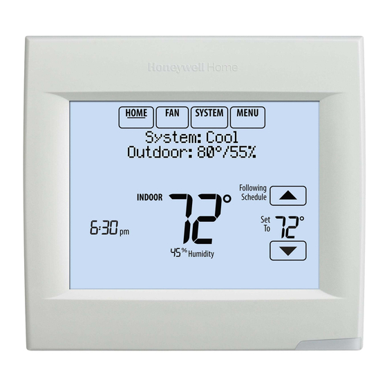
VISIONPRO® 8000 SMART THERMOSTAT HOME. Touch to display Home screen. FAN. Select fan mode. SYSTEM. Select system mode (Heat/Cool). MENU. Touch to display options. Start here to set a program schedule. Current status. Shows system mode (heat/cool), outdoor ® temperature (with optional outdoor sensor, or Wi-Fi connection) and humidity (requires Wi-Fi connection). -
Page 41: Setting System Mode
VISIONPRO® 8000 SMART THERMOSTAT 3. Touch Done to save and exit. NOTE: The Auto and Em Heat system settings may not • On: Fan is always on. appear, depending on how your thermostat was • Auto: Fan runs only when heating or cooling installed. -
Page 42: Permanent Hold
VISIONPRO® 8000 SMART THERMOSTAT NOTE: Touch Cancel Period to eliminate any unwanted time period. Touch Fan Setting to customize fan settings for Use Scheduling any time period. Assistant? Overriding Schedules: Residential MCR34102 1. Touch to adjust the temperature (right side of screen) and the Hold Until time (left side). -
Page 43: Viewing Equipment Status
VISIONPRO® 8000 SMART THERMOSTAT • Touch Override to use a pre-set occupied temperature if a person uses the room during an unoccupied period. The new temperature will be maintained for 1 hour and can be adjusted up to the maximum time set by the Heat Stage 1: Off installer. - Page 44 VISIONPRO® 8000 SMART THERMOSTAT 5. Touch Done to save your settings. Setting Custom Events: Commercial Jul 25 - Jul 26 Heat: 72 Cool: 78 This feature lets you customize temperature settings to be maintained during a specific event. You can set up an event for a specific date or day in a month.
- Page 45 VISIONPRO® 8000 SMART THERMOSTAT 4. Touch to select the Heat and Cool tempera- tures. Schedule adjusted to 62 in heating Temperature During Holiday MCR34118 Fig. 58. Setting Holiday Schedule: Commercial Use This feature lets you customize temperature settings to be maintained on specified national holidays.
- Page 46 VISIONPRO® 8000 SMART THERMOSTAT Adjusting Humidification Settings 1. Touch MENU and select Humidification. Temperature While Away MCR34100 Fig. 66. Humidification Window Protection MCR34123 MCR34128 Fig. 64. 4. Review the settings and touch Done to save them. Fig. 67. Touch Cancel to ignore the changes. 2.
- Page 47 VISIONPRO® 8000 SMART THERMOSTAT cold outdoor temperatures, poorly insulated windows require a lower Window Protection setting, which will limit how much your humidifier can run. Dehumidification 7. After you set the Window Protection setting, check for frost/condensation on your windows in the morning. Equipment Status If frost/condensation is present, adjust the Window Protection setting to the next lowest number and...
- Page 48 VISIONPRO® 8000 SMART THERMOSTAT Adjusting Dehumidification Adjusting Ventilation Settings Settings: Commercial Use 1. Touch MENU, and select Ventilation. This feature can control a dehumidifier or use your air conditioner to reduce humidity. MCR34100 1. Touch MENU and select Dehumidification. Fig. 76. MCR34100 Fig.
-
Page 49: Cleaning The Thermostat Screen
VISIONPRO® 8000 SMART THERMOSTAT Temporary Boost: Touch to select how long to run 2. Select an option and follow prompts: ventilation temporarily. To turn it off, set it to zero. • Reminders to change filters • Fahrenheit/Celsius display •... -
Page 50: Adjusting Security Settings
VISIONPRO® 8000 SMART THERMOSTAT 3. Touch Yes. A countdown timer displays elapsed time • Unlocked: Full access allowed. until the screen is reactivated. • Partially locked: Only temperature can be changed. • Fully locked: No access allowed. Clean screen for 30 seconds? Lock Mode Unlocked MCR34141... -
Page 51: Advanced Features
VISIONPRO® 8000 SMART THERMOSTAT Advanced Features P + I CONTROL A conventional mechanical or electronic thermostat does not control temperature precisely at setpoint. Typically ADAPTIVE INTELLIGENT RECOVERY (RESIDENTIAL there is an offset (droop) in the control point as the system USE ONLY) load changes. -
Page 52: Staging Control
VISIONPRO® 8000 SMART THERMOSTAT U1 Contacts • Humidification (ISU 803) • Dehumidification (ISU 904) • Ventilation (ISU 1002) Installer Options • Cool Stage 3 (ISU 208) • Conventional Heat Stage 3 (ISU 210, 214) • Backup Heat Stage 2 for Heat Pumps (ISU 217) •... - Page 53 VISIONPRO® 8000 SMART THERMOSTAT TO CHANGE DIFFERENTIAL SETTINGS When the Backup Heat Droop is set to 2 °F or higher, 1. Select Advanced Options to view/adjust differentials backup heat is not used unless the indoor temperature between all stages. drops to the Backup Heat Droop setting or the Backup Heat Upstage Timer expires, whichever occurs first.
- Page 54 VISIONPRO® 8000 SMART THERMOSTAT Multistage Control Multistage Control keeps the high stage of the equipment running until the desired setpoint is reached. This setting is recommended for Geothermal Heat Pumps to allow the loop to rest. To view/adjust “Finish with High Heat Stage” or “Finish with High Cool Stage,”...
-
Page 55: Heat Pump And Backup Heat Operation
VISIONPRO® 8000 SMART THERMOSTAT HEAT PUMP AND BACKUP HEAT OPERATION Heat pump with outdoor temperature lockouts Outdoor temperature lockouts are optional. See Installer Setup options (ISU 312). Alert Light - General Heat as needed to maintain the desired temperature. The thermostat allows you to set differential temperature An alert light is located in the lower right corner of the settings between each stage if you want the equipment to... - Page 56 VISIONPRO® 8000 SMART THERMOSTAT Fossil Fuel Backup Heat (Backup Heat NOT Allowed to Run with Heat Pump) HEAT MODE The thermostat turns on Backup Heat only when the indoor temperature drops to the selected Backup Heat Droop setting or the Backup Heat Upstage Timer expires (whichever occurs first).
-
Page 57: Indoor Air Quality (Iaq) Control
VISIONPRO® 8000 SMART THERMOSTAT your windows during cold outdoor temperatures, poorly insulated windows require a lower Window Protection setting, which will limit how much your humidifier can run. After you set the Window Protection setting, check for frost/condensation on your windows in the morning. If frost/condensation is present, adjust the Window Protection setting to the next lowest number and check for frost/condensation on your windows the next morning. - Page 58 VISIONPRO® 8000 SMART THERMOSTAT 2. Select the terminals wired to the humidifier. See perature. The humidifier is allowed to run Fig. 116. again after the discharge temperature rises above the dew point temperature. NOTE: U1 are Normally Open Dry Contacts that require power from the system transformer or a separate transformer.
-
Page 59: Control Humidification Level
VISIONPRO® 8000 SMART THERMOSTAT 5. If frost or condensation appears on the windows, press MENU, scroll down and select Window Protec- tion. Fig. 124. 6. Window Protection is set on a scale from 1–10. A set- Fig. 120. ting of 1 represents poorly insulated windows and a NOTE: ISU 1014 gives the option to lockout ventila- setting of 10 represents well insulated windows. -
Page 60: Set Up Dehumidification With Cooling System
VISIONPRO® 8000 SMART THERMOSTAT If set for A/C with Low Speed Fan, configure U1 as normally 3. Select whether the U1 terminal are Normally Open or open or normally closed (ISU 905) and wire to the Low Normally Closed. See Fig. 128. Speed Fan terminal on the equipment. - Page 61 VISIONPRO® 8000 SMART THERMOSTAT 1. Select the Dehumidification Equipment in ISU 900. See Fig. 130. Fig. 130. Fig. 133. 4. Set Dehumidifier Fan Control settings. See Fig. 134. • Tstat Controls Fan Thermostat turns on the dehumidifier and the fan when dehumidification is needed.
-
Page 62: Set Up Dehumidification Away Mode
VISIONPRO® 8000 SMART THERMOSTAT Dehumidification Away Mode Set up Dehumidification Away Mode Dehumidification Away Mode protects the home when 1. Select Allowed at ISU 918. See Fig. 138. unoccupied for long periods of time during hot and humid weather by maintaining the desired humidity and temperature settings. -
Page 63: Control Dehumidification Level
VISIONPRO® 8000 SMART THERMOSTAT • Low Limit Temperature Setting Control Dehumidification Level If the cooling system is used to control humidity 1. Touch MENU and select Dehumidification. while Dehumidification Away Mode is active, the thermostat allows the cooling system to lower the indoor air to the Low Limit Temperature Setting to reach the Dehumidification Setting at ISU 920. -
Page 64: Set Up Dehumidification With Cooling System
VISIONPRO® 8000 SMART THERMOSTAT humidification and dehumidification settings. The heating coil (heat exchanger). This feature requires a thermostat will automatically switch between conventional forced air heating system (gas, oil, or electric) humidification and dehumidification to maintain the in the application. desired humidity level. -
Page 65: Set Up Dehumidification With Dehumidifier
VISIONPRO® 8000 SMART THERMOSTAT 3. Select whether the U1 terminal is Normally Open or Dehumidification using a Dehumidifier Normally Closed. See Fig. 147. The Dehumidifier option requires a dedicated unit for • Normally Open – contacts are normally open and dehumidification. -
Page 66: Control Dehumidification Level
VISIONPRO® 8000 SMART THERMOSTAT 3. Select the system mode(s) to allow dehumidification. 5. Set the desired lockout option. See Fig. 153. See Fig. 151. NOTE: Heat includes Heat, Emergency Heat and Auto. If the system is in Auto mode, the ther- mostat will allow dehumidification if the last call was for heat. -
Page 67: Ventilation
VISIONPRO® 8000 SMART THERMOSTAT 2. Select Auto. turn Off during Sleep period, turned off by user, etc.), ASHRAE 62.2 is not met during those times. See ISU 1012 to select a Ventilation Priority. • Percent On Time The thermostat operates ventilation equipment based Dehumidification on a percentage entered in the installer setup (ISU Auto... -
Page 68: Set Up Ventilation
VISIONPRO® 8000 SMART THERMOSTAT NOTE: This feature requires a wired sensor for outdoor 3. Select the Ventilation Control Method. See “Ventila- temperature limits, or Internet connection for tion Control Methods (ISU 1005)” on page 67 for temperature and humidity lockouts. more information. - Page 69 VISIONPRO® 8000 SMART THERMOSTAT This setting determines how often the ventilation thermostat will override the outdoor lockouts and equipment will operate to meet the ASHRAE 62.2 run ventilation. When using this option, it is rec- Standard. The thermostat will indicate the following ommended to increase the rate (CFM) of the ven- based on the Equipment Ventilation Rate, Square tilation equipment to meet the ASHRAE 62.2...
- Page 70 VISIONPRO® 8000 SMART THERMOSTAT When ISU 1012 Ventilation Priority is set to Lockouts are 8. If Percent On Time was selected for ISU 1005, select Priority, or ISU 1005 Ventilation Control Methods is set to the Ventilation Percent on Time. See Fig. 164. Percent On Time, the thermostat will indicate whether this meets or may not meet the ASHRAE 62.2 Standard or the Percent On Time setting.
- Page 71 VISIONPRO® 8000 SMART THERMOSTAT mostat will indicate whether this meets or may not 2. Select Mode, Temporary Boost, or Lockout, then meet the ASHRAE 62.2 Standard or the Percent On select appropriate options. Time setting. See Fig. 168. NOTE: ISU 1014 Lockout Ventilation on Humidifi- cation or Dehumidification Calls is not an Mode option when you select ASHRAE is Priority at...
-
Page 72: Iaq Reminders
VISIONPRO® 8000 SMART THERMOSTAT 3. Select the reminder you want to set. 4. Press to set the timer length. Ranges, incre- ments, and units will change based on the reminder. Lockout in Sleep NOTE: When set for run time days, the thermostat Period: tracks the amount of time the fan has run and compares that time against the number... - Page 73 VISIONPRO® 8000 SMART THERMOSTAT You can change or create custom reminders in ISU 1200. 4. Press the up or down arrows to set the outdoor tem- perature and press Next. Fig. 179. Fig. 182. For example, to set up a Fall Service Reminder based on NOTE: A seasonal maintenance reminder will appear Outdoor Temperature: when the outdoor temperature reaches the level...
- Page 74 VISIONPRO® 8000 SMART THERMOSTAT 7. When the user touches Press HERE for info on the 10. To clear the Alert, (and turn off the Red Alert Light on Home Screen, the reminder message will be dis- the thermostat), select Dismiss. played.
- Page 75 VISIONPRO® 8000 SMART THERMOSTAT 5. Touch Press HERE to edit to set the reminder mes- 8. Select whether you want the reminder to appear only sage (see Fig. 191). once or to be recurring, and press Next. Fig. 191. Fig. 194. 6.
- Page 76 VISIONPRO® 8000 SMART THERMOSTAT 12. When the user touches Press HERE for info on the • Dismiss Home Screen, the reminder message will be dis- • View Dealer Info played: 14. Selecting View More Info displays the Custom Reminder message. Scroll to see: Call XYZ for Indoor Quality...
-
Page 77: Commercial Features
VISIONPRO® 8000 SMART THERMOSTAT COMMERCIAL FEATURES • Touch Override to use a pre-set occupied temperature if a person uses the room during an unoccupied period. The new temperature will be maintained for 1 hour and The thermostat can be setup for residential or light can be adjusted up to the maximum time set by the commercial applications (ISU 101). - Page 78 VISIONPRO® 8000 SMART THERMOSTAT Select Occurence Custom Events Specific Date US Holidays MCR34114 MCR34117 Fig. 204. Fig. 207. 4. Make selections as prompted on each screen. For 4. Review the settings and touch Done to save them. more information, see next two pages. Touch Cancel to ignore the changes.
- Page 79 VISIONPRO® 8000 SMART THERMOSTAT 3. Touch to select the Heat and Cool tempera- tures, then touch Next to select return date. Select US holidays New Year’s Day Temperature While Away MCR34120 Fig. 210. 4. Touch to select the Heat and Cool tempera- tures.
-
Page 80: Ramp Rates (Commercial Use)
VISIONPRO® 8000 SMART THERMOSTAT Ramp Rates (Commercial Use) Economizer and Time of Day (TOD) Operation When the ramp rate is set to Off, the thermostat begins recovery at the scheduled time. Economizer When a ramp rate is set, recovery begins early to reach the setpoint by the program time. -
Page 81: Pre-Occupancy Purge
VISIONPRO® 8000 SMART THERMOSTAT Time of Day (TOD) The thermostat can be set up for a Time of Day output in the installer setup. This output is commonly used to control lighting panels, turning them on for occupied periods and off for unoccupied periods. -
Page 82: Temperature Display
VISIONPRO® 8000 SMART THERMOSTAT Temperature Display The temperature reading displayed on the home screen is from the sensor or sensors that are being used for temperature control. In Fig. 221, the temperature reading is the average of the thermostat internal sensor and the indoor sensor. Fig. - Page 83 VISIONPRO® 8000 SMART THERMOSTAT Calibration - Outdoor Sensor Table 7. C7089U1006 Sensor Resistance at Outdoor Temperature. (Continued) The C7089U1006 Outdoor Sensor is calibrated at the factory and cannot be recalibrated in the field. Outdoor Outdoor Temperature Temperature Ohms of Ohms of Table 7.
-
Page 84: Wiring
VISIONPRO® 8000 SMART THERMOSTAT WIRING Table 9. Thermostat Terminal Designation Descriptions. Conventional System Heat Pump Terminal Description Terminal Description Common wire from secondary side of cooling Common wire from secondary side of cooling transformer (if 2 transformers). transformer. Cooling power Cooling power Heating power Heating power... - Page 85 VISIONPRO® 8000 SMART THERMOSTAT Wiring with the THP9045 C-Wire Adapter The THP9045 C-wire adapter is designed to be used with applicable thermostats in which a 24V common is required and there are not enough wires. The K terminal on the thermostat can be used to operate both the fan and compressor on a single wire, and the module is designed to receive the signal from the K terminal, split that signal and re-route it to operate the compressor and/or fan for normal operation.
-
Page 86: Wiring Iaq Equipment Or A Heat/Cool Stage To The U1 Terminals
VISIONPRO® 8000 SMART THERMOSTAT Wiring IAQ Equipment or a Heat/Cool Stage to the U1 Terminals To Thermostat “U” terminals can be used for humidification, dehumidification, ventilation or a stage of heating/cooling. SYSTEM SYSTEM TRANSFORMER TRANSFORMER THERMOSTAT THERMOSTAT HUM, DEHUM OR FIELD INSTALL JUMPER VENT BETWEEN R AND U1... -
Page 87: Wiring Economizer Control
VISIONPRO® 8000 SMART THERMOSTAT Wiring Economizer Control FURNACE, AIR-HANDLER, OR RTU AUX2-1 E-GND EXH1 AUX1-0 A-L/A TH8321WF Y2-I Y2-O Y1-I Y1-O W7220 JADE ECONOMIZER M37209 Fig. 229. Economizer control with economizer fault alert using TH8321WF. NOTES: Configure the TH8321WF to control economizer (see settings for ISU 222). FURNACE, AIR-HANDLER, OR RTU... -
Page 88: Wiring C7089U1006 Outdoor Sensor
VISIONPRO® 8000 SMART THERMOSTAT Wiring C7089U1006 Outdoor CAUTION Sensor Electrical Shock Hazard. Can cause electrical shock or equipment damage. Disconnect power supply before connecting wiring. CAUTION Wiring must comply with applicable codes, ordinances and Electrical Interference (Noise) Hazard. regulations: Can cause erratic system operation. Keep wiring at least one foot away from large 1. -
Page 89: Wiring Guide - Wired Indoor Sensors
VISIONPRO® 8000 SMART THERMOSTAT Wiring guide — Wired Indoor Sensors Wiring 2 TR21 sensors (20k ohm) and 1 TR21-A sensor CAUTION (10k ohm) for temperature averaging network. Select 20K in the Installer Setup (ISU 503) when using 2 TR21 sensors Electrical Interference (Noise) Hazard. -
Page 90: Troubleshooting
VISIONPRO® 8000 SMART THERMOSTAT TROUBLESHOOTING Table 10. Troubleshooting. Symptom Action Screen is blank • Check circuit breaker and reset if necessary. • Make sure power switch at heating and cooling system is on. • Make sure furnace door is closed securely. Screen is •... -
Page 91: Regulatory Information
VISIONPRO® 8000 SMART THERMOSTAT REGULATORY INFORMATION FCC Compliance Statement IC Regulations This device contains licence-exempt § 15.19 (A)(3) (USA ONLY) transmitter(s)/receiver(s) that comply with Innovation, This device complies with part 15 of the FCC Rules. Science and Economic Development Canada’s licence- Operation is subject to the following two conditions: exempt RSS(s). - Page 92 33-00096—04 M.S. Rev. 05-19 | Printed in United States This product is manufactured by Resideo Technologies, Inc., Golden Valley, MN, 1-800-468-1502 ©2019 Resideo Technologies, Inc. The Honeywell Home trademark is used under license from Honeywell International Inc. All rights reserved.
Need help?
Do you have a question about the TH8321 and is the answer not in the manual?
Questions and answers
I have a honeywell TH8321 R 1001 thermostate. I need to put more humidity in the house but I can not accomplish that.l The wondow protection is set at 10 which turns the himidity off in the house. my question is how do I turn the window protection off or adjust it so I can put more himidity in the house. Currently the himidty is 32%. Thanks for your help
To turn off or adjust the Window Protection setting on a Honeywell TH8321 thermostat to increase humidity in your house:
1. Ensure the thermostat is connected to an outdoor wired sensor or the Internet (Window Protection is only available with these connections).
2. Access the thermostat menu.
3. Locate the Window Protection setting.
4. Set Window Protection to "Off" to allow the humidifier to run up to the desired humidity setting without restriction.
5. If you prefer to adjust rather than turn it off, lower the Window Protection setting step by step and check for frost or condensation on windows each morning.
6. Continue adjusting to a lower number until no frost or condensation is present.
This will allow higher humidity levels in your home while preventing excessive condensation on windows.
This answer is automatically generated