
Related Manuals for Sony BPU4800


Summary of Contents for Sony BPU4800
- Page 1 4-599-596-15 (1) Baseband Processor Unit Operating Instructions Before operating the unit, please read this manual thoroughly and retain it for future reference. BPU4800 © 2016 Sony Corporation...
-
Page 2: Table Of Contents
Table of Contents Overview..............3 System Configuration ............4 Name and Function of Parts ........6 Front Panel ..............6 Rear Panel ..............7 Connection and Setup..........10 4K System Connection ..........10 Extension Mode (HD System) Connection ....11 HFR Data Transfer Connection ........12 Relationship between Operation Mode and Output Slots ................12 About Recording Times ..........14... -
Page 3: Overview
Overview The BPU4800 Baseband Processor Unit connects to an HDC4800 Color Camera, using an optical fiber cable, and performs signal processing and video output of the signal from the camera. The unit is equipped with high-speed, large-capacity storage for recording and playback of signals from a camera. -
Page 4: System Configuration
System Configuration Note Production of some of the peripherals and related devices shown in the figures may have been discontinued. For advice on choosing devices, please contact your Sony representative. HDC4800 connection example PWSK-4403 PWS-110NM1 HDVF-550/C730W/ PWS-110PR1 NXL-FR318 C550W/EL75/L750/L770 Viewfinder... - Page 5 REF IN MENU LOCK UNLOCK SYSTEM NETWORK MENU ACCESS COM ERROR SHARE PLAY DISP CANCEL FAN STOP OPTICAL CONDITION MENU ENTER HDC4800 BPU4800 Color Camera 10GbE CCA-5 Sync signal/ 4K/HD 4K/HD PWS-110MG1 return video monitor monitor monitor input Live Replay RCP-1500 series a) Install NXLK-IP40F SDI-IP converter board (option).
-
Page 6: Name And Function Of Parts
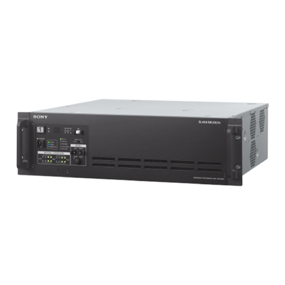
Name and Function of Parts Front Panel NMI STATUS LIVE REPLAY REF IN MENU LOCK POWER UNLOCK SYSTEM NETWORK MENU ACCESS COM ERROR SHARE PLAY DISP CANCEL FAN STOP OPTICAL CONDITION MENU ENTER USB connector (for service personnel) a Red tally light UNLOCK (red): Indicates operation is not synchronized to Turns on when a red tally signal is received. -
Page 7: Rear Panel
SHARE PLAY indicator One green indicator (2nd from right): Receive signal Indicates whether content can be shared using Share Play. condition is OK. Flashing orange: Before genlock One yellow indicator (2nd from left): Receive signal level is Flashing green: Genlock operating low. - Page 8 (LAN) connector (RJ-45 8-pin) dedicated RJ45 to D-Sub adaptor cable. Connects to a camera control system LAN. Connect to a LAN SONY VTR/Disk protocol, VDCP, and Odetics control hub (10BASE-T/100Base-TX) using a LAN cable (shielded protocols are supported. type, category 5 or higher).
- Page 9 They can also output signals with superimposed text characters and markers. w 3G/HD SDI OUTPUT connector (SLOT2 LIVE) (BNC type) Outputs video signals from the video camera as 3G-SDI signals or HD-SDI signals. The same signal is output from each connector grouped in pairs.
-
Page 10: Connection And Setup
For details about assignment of BNC connectors, see “Relationship between Operation Mode and Output Slots” (page 12). Settings Device Setting Menu/Page Item Set value BPU4800 Image format settings CONFIGURATION/<OUTPUT FORMAT> SYSTEM RESOLUTION 3840×2160 FORMAT FREQUENCY Displays value set on CCU. -
Page 11: Extension Mode (Hd System) Connection
Device Setting Menu/Page Item Set value HDCU2000 Image format settings SYSTEM OPERATION/ FREQUENCY HD Frame frequency /2500 <MULTI FORMAT> HD-SD 0-Delay, Frame (1F) DELAY Video output connector SYSTEM OPERATION/ SLOT1 to Video output format of settings <OUTPUT FORMAT> SLOT6 each slot Can also be set using the control panel. -
Page 12: Hfr Data Transfer Connection
Settings Device Setting Menu/Page Item Set value BPU4800 Image format settings CONFIGURATION/ SYSTEM RESOLUTION 3840×2160 <OUTPUT FORMAT> FORMAT FREQUENCY Frame frequency Video output connector CONFIGURATION/ SLOT1 to Video output format of each settings <OUTPUT FORMAT> SLOT3 slot Can also be set using the control panel. - Page 13 Live output QFHD 3840×2160 SLOT1 LIVE SLOT2 LIVE SLOT3 LIVE Picture size 3840×2160 1920×1080 1280×720 1920×1080 1280×720 Frame rate 59.94p, 50p 59.94p, 50p 59.94i, 50i 59.94p, 50p 59.94i, 50i 59.94p, 50p Output format 3G-A/3G-B 3G-A/3G-B 1.5G 1.5G 1.5G NMI-LAN SLOT1 LIVE NMI SLOT2 NMI Picture size 3840×2160...
-
Page 14: About Recording Times
Replay output QFHD 3840×2160 SLOT1 REPLAY SLOT2 REPLAY SLOT3 REPLAY Picture size 3840×2160 1920×1080 1280×720 1920×1080 1280×720 Frame rate 59.94p, 50p 59.94p, 50p 59.94i, 50i 59.94p, 50p 59.94i, 50i 59.94p, 50p Output format 3G-A/3G-B 3G-A/3G-B 1.5G 1.5G 1.5G NMI-LAN SLOT1 REPLAY NMI SLOT2 NMI Picture size 3840×2160... - Page 15 Recording format Recording time Number of SKC-MEM4 extension memory boards Recording rate Picture size Frame rate Normal (speed) 1 board 2 boards 3 boards 960fps (16×) 1h 20m 2h 40m 4h 0m 5h 20m 480fps (8×) 2h 40m 5h 20m 8h 0m 10h 40m 59.94p...
-
Page 16: Status Display
Status Display BPU Menu Settings The device and system status can be monitored using text The device and system status can be monitored and settings characters superimposed on the output signal of the SLOT3 can be modified using the menu displayed in the video output LIVE monitor. - Page 17 Turn the control knob to move the , cursor to the To change page desired input field and push the knob. The , cursor changes to a flashing ? (question mark). Check that the , cursor is pointing to the page number then push the control knob.
-
Page 18: Menu Tree
DIAGNOSIS menu Menu Tree OPTICAL LEVEL OPTICAL LEVEL (D01) CABLE LENGTH CONFIGURATION menu BOARD STATUS (D02) BARS 2SI DIAMOND MARKER (C01) BPU BARS DPR1 BARS TYPE DPR2 SYSTEM SETTINGS (C02) SYSTEM FORMAT CONNECTION STATUS RESOLUTION (D03) CABLE FREQUENCY COMM COLOR MODE HDR MODE CABLE OUTPUT FORMAT (LIVE) -
Page 19: Menu List
Menu List Legend The following conventions are used in the menu tables. Settings ON, OFF, 0, etc.: Factory default settings shown underlined. ENTER to execute: Execute by pushing the control knob or setting the CANCEL/ENTER lever to the ENTER position. CONFIGURATION menu Page name Item... - Page 20 Page name Item Set value Meaning Page No. <OUTPUT FORMAT SLOT1 SLOT1 output format settings (LIVE)> 3840×2160, 1920×1080 SLOT1 output video resolution setting SQD, 2SI SLOT1 4K video division output method setting SQD: Square Division (quadrants) 2SI: 2-sample Interleave (The IP output is 2SI, even when SQD is selected.) HD-SDI, 3G(Lv-A), 3G(Lv-B) SLOT1 video output system setting OETF...
- Page 21 Page name Item Set value Meaning Page No. <RETURN> SDI1 1080/59.94i(PsF), 1080/59.94P, Format of video signal input on SDI1 connector 1080/50i(PsF), 1080/50P, (display only) NO SIGNAL, --- ---: When a CCU is connected Available only for extension connection. SDI2 1080/59.94i(PsF), 1080/59.94P, Format of video signal input on SDI2 connector 1080/50i(PsF), 1080/50P, (display only)
- Page 22 Page name Item Set value Meaning Page No. <NETWORKED MEDIA NETWORK SLOT 1 LIVE NMI LAN1, SLOT 1 Selects the network interface to be set/displayed. INTERFACE> INTERFACE LIVE NMI LAN2, SLOT 1 REPLAY NMI LAN1, SLOT 1 REPLAY NMI LAN2, SLOT 2 NMI LAN1, SLOT 2 NMI LAN2 DHCP OFF, ON...
- Page 23 DIAGNOSIS menu Page name Item Set value Meaning Page No. <OPTICAL LEVEL> OPTICAL LEVEL Bar graph display Bar graph display of optical signal level condition between the unit and the CCU. CABLE LENGTH x.x km Length of the optical fiber cable between the CCU and camera head <BOARD STATUS>...
-
Page 24: Web Menu Settings
Accessing over a network Web Menu Settings When accessing files using a network cable, you can also transfer files while recording or playback is in progress. However, since camera signal recording and replay output have priority, the transfer rate over the network may decrease depending on input/output port usage. -
Page 25: Home Screen
Home screen: Displays the operating status of unit’s boards Maintenance screen: Used for maintenance of the unit. For and the network. details about this screen, refer to the Maintenance Status screen: Displays a list of errors and warnings that Manual. have occurred on the unit. - Page 26 HFR (high frame rate) Data Record Port The following information is displayed. Simple display Detailed display a Recording format f Remaining capacity [FILE] displays the video format of the recording. Displays the remaining memory capacity. When a loop recording area is specified, this displays the b File name capacity of the writable area of the capacity assigned to the Displays the name of the file being recorded.
- Page 27 c Time code display • CLOSE Displays time code data (TCR). • STOP In detail display mode, UBR, TM1, and TM2 are also • PLAY (playback speed) displayed simultaneously. • SHUTTLE (playback speed) • JOG (FWD/REV) d [Setting] button • VAR (playback speed) Displays the [Port] screen (page 35) for the corresponding •...
-
Page 28: Status Screen
Status Screen Displays a list of errors and warnings that have occurred on the unit, and the power supply status. Click the button, turning it on, to update the display automatically. Error/Warning Status Power Out Displays the output power. Displays a list of errors and warnings. Power In Power Supply Status Displays the input power. - Page 29 Setup tab Makes basic operating mode settings of the unit. System Parameters QFHD SDI with TC Selects whether to superimpose the time code on the output Preroll Time from SLOT1 REPLAY SDI OUT 1/2 only or on all SDI signals, Sets the preroll time in units of seconds.
- Page 30 • Playable Replay Port: Information about playable files on Selects the protocol used on the REMOTE 1/2 connectors. the replay port • VTR/DISK: SONY VTR/Disk protocol • Editable Replay Port: Information about files that can be • VDCP: VDCP protocol switched seamlessly during playback on the replay port •...
- Page 31 Replay Port: Replay Port or HD Cut Out Port GPIO Parallel Input Setup Assigns the commands for the input side of the GPIO (25-pin) Protocol Setting connector. A 32-byte setting can be specified for pin 1 to pin 11. VDCP Clip End Mode Sets whether the to automatically play the next clip or GPIO Parallel Output Setup whether to stop playback upon reaching the end of a clip...
- Page 32 IP Address: 192.168.0.10 Import Clips with Odd Frames (50p & 59.94p) Subnet Mask: 255.255.255.0 Selects the processing to perform when the last frame is odd Default Gateway: 0.0.0.0 when importing 50p or 59.94p files. MTU: 1500 • Not Acceptable: Do not import. •...
- Page 33 Share Play Tx:Rx Setting Specify the number of Share Play output transmitters (Tx) and receivers (Rx) to guarantee the network storage bandwidth for the selected video format. Bank tab Makes settings for user banks of saving settings. Bank Recall Factory Setting Click the [Recall] button to return the settings on the System screen to their default factory values.
- Page 34 Power tab Used to reboot and shut down the unit. Log Out Click the [Log Out] button to log out from the web menu. Reboot Click the [Start] button to close all ports and reboot the unit.
-
Page 35: Port Screen
Port Screen Makes settings for each port of the unit. HFR (high frame rate) Data Record Port Port information TCG Source Selects the source signal for synchronizing the internal time Displays the operating status of the selected port. The display code generator. - Page 36 Note This setting is valid only when [TCG Source] is set to “Internal-Preset” and the frame frequency is 29.97 Hz. Timer Select Selects the time data to display. • TC • UB • TM1 • TM2 Timer Set Displays the time counter. To change the counter, enter a value and click the [Set] button.
- Page 37 Replay Port / HD Cut Out Port Port information Remote 25pin Selects whether to enable remote control from the device Displays the operating status of the selected port. The display connected to the GPIO (25-pin) connector. is the same as on the Home screen. •...
- Page 38 • File List Repeat Vertical Position Sets the vertical display position of character information. Feed Play Mode • 0 (top) to 22 to 255 Sets the playback speed of feed play. If the playback speed is controlled using the PWA-PRC1 Horizontal Position application, this setting is ignored.
-
Page 39: File Screen
• CH05 - CH06 Muting • CH07 - CH08 Shuttle Muting • CH01 - CH04 • CH05 - CH08 Sets whether to output the audio signal during shuttle • CH01 - CH06 playback. • CH01 - CH08 • Off: Output •... -
Page 40: Storage Screen
File List Displays the file list. To filter the files using options, specify the search criteria in [Select Condition] and click the [Load] button. To filter the currently displayed files using different search criteria, change the setting in [Select Condition] and click the [Select] button. - Page 41 Storage Graph Storage Information Displays a graph of the usage status of each recording area Displays information about memory boards A to D. in internal memory. Model Name File System Information Displays the model name of the memory board. Serial Number Last Formatted Date Displays the serial number of the memory board.
- Page 42 Loop tab Assigns the recording area for each input/output when using loop recording. The recording loops back to the start of the loop recording area when it reaches the end of the area, overwriting the file. If there is more than one file in the loop recording area, files are overwritten starting with the oldest file.
-
Page 43: File Operations Via Ftp
Enter a user name of “usr1” and press the Enter key. Directory structure If the user name is authenticated, you will be prompted The following diagram shows the BPU4800 internal directory for a password. structure that is visible on the computer. - Page 44 Authenticates a password. The following mode codes exist. However, this unit transmits Syntax: PASS <SP> <password> <CRLF> code “S” regardless of the specified code. Example: PASS bpu4800 • S: Stream mode (default) • B: Block mode QUIT • C: Compressed mode Example: MODE S Terminates the FTP connection.
- Page 45 - Non-audio information (1-bit × 16 channels) Copies MXF files on the computer to the current directory. - Emphasis information (2-bit × 16 channels) Syntax: STOR <SP> <path_name> <CRLF> - Recording model information (15: BPU4800) - Playback permission information and editing permission Example: STOR FILE00000010.mxf information •...
- Page 46 Syntax: CWD <SP> <path_name> <CRLF> Switches to the following directory, depending on the presence or otherwise of the directory specified in <path_name>. • When a directory is specified: The specified directory • Nothing specified: The root directory Example: CWD InternalStorage1 CDUP Changes the current directory to the directory one level up (parent directory).
-
Page 47: Appendix
For details The salvage process can take a few seconds or up to 10 on parts replacement, contact your Sony representative. minutes, depending on the state of the memory when the recording was interrupted. -
Page 48: Error Messages
If the error message appears again when the unit is appears on the web menu screen. turned on, contact your Sony representative. Code Indication Description 14xx00 PS FAN1 TROUBLE, etc. -
Page 49: Warning Messages
Code Indication Description D5xx01 SLOT Mx INTERFACE ERROR1, etc. Cannot use memory because cannot communicate with the memory inserted in the unit. If this error persists after turning the unit on again, the unit or memory may be faulty. D6xx01 SLOT Mx UNMOUNT ERROR1, etc. - Page 50 Code Indication Description 1C01pp PORT x NO A7/A8 INPUT (P-x NO A7/A8) Carrier cannot be detected on digital audio channel 7/channel 8 input of the displayed port. 210101 SLOT MX REC INHIBIT Cannot record to memory due to a menu setting. (REC INHBIT) 220201 SLOT MX FS LOCKED...
-
Page 51: Displaying The Error Log
Memory status messages The following warning messages appear depending on the appear, it is time to replace with new memory. Specifically, if wear or usage of the memory. Using memory repeatedly the “CONDITION x BAD” message appears, it is best to gradually increases the possibility that errors will occur during replace with new memory as soon as possible. -
Page 52: Specifications
Before Using this Unit (1) than 300 meters (984 feet). Operating Instructions (CD-ROM) (1) Cable, RJ45-DSUB Part No. 1-848-424-12 (SONY) (1) Optional accessories United States and Canada: Power cord set (1-551-812-XX) Other areas: Power cord set (1-782-929-XX) CCA-5-3 (3 m) and CCA-5-10 (10 m) connection cables... - Page 53 On the basis of license contracts between Sony and the software copyright holders, this product uses open software. To meet the requirements of the software copyright holders, Sony is obligated to inform you of the content of these licenses. For details about licenses, refer to “License1.pdf” in the “License”...
Need help?
Do you have a question about the BPU4800 and is the answer not in the manual?
Questions and answers