
Related Manuals for Sony BPU4500


Summary of Contents for Sony BPU4500
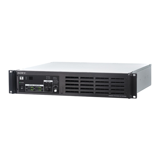
- Page 1 BASEBAND PROCESSOR UNIT BPU4500 OPERATION MANUAL [English] 1st Edition (Revised 1)
-
Page 2: Table Of Contents
Table of Contents Overview ..............3 System Configuration ............. 4 Name and Function of Parts ........9 Front Panel ..............9 Rear Panel ..............10 Connection and Setup ..........12 4K System Connection ..........12 Extension Mode Connection ......... 13 HD CUTOUT Video System ......... -
Page 3: Overview
SDI but also as IP. 1) Requires PMW-F55 software version 2.10 or later. 2) Requires the SKC-4065 F65 Adaptor. 3) Requires BPU4500 software version 1.31 or later. Also, connection with an HDC-P43 requires an HKCU-SM100 CCU Extension Adaptor and single-mode fiber cable. -
Page 4: System Configuration
Note Production of some of the peripherals and related devices shown in the figures may have been discontinued. For advice on choosing devices, please contact your Sony representative. PMW-F55 connection example Connection example of PMW-F55 and HDCU2000/2500 for operation as a system camera. - Page 5 DVF-EL100 CA4000 Camera DVF-L350 Network Switch System Adaptor Viewfinder Optical fiber cable Optical fiber cable CCA-5 BPU4500 Lens RCP-1000 series PMW-F55 Solid-state Remote Control Panel Memory Camcorder Sync signal input DC power supply input Return video input a) Install NXLK-IP40F SDI-IP converter board (option).
- Page 6 Viewfinder Monitor Monitor Network Switch SKC-4065+CA4000 +SKC-PB40 Optical fiber cable Lens Optical fiber cable USB flash drive BPU4500 CAC-6 Return Video Digital Motion Picture Selector Camera Sync signal input BP-8 Bridge Plate Intercom Headset (ARRIFLEX) Return video input Intercom microphone...
- Page 7 Monitor Monitor Optical fiber cable Network Switch USB flash drive Optical fiber cable CAC-6 Return Video VCT-14 Tripod Selector Adaptor Intercom Headset BPU4500 CAC-12 Tripod Sync signal input Microphone Microphone Holder Return video input Intercom microphone input HDC4300 Color CCA-5...
- Page 8 Multi Purpose Camera Single-mode fiber Lens cable (ST Optical fiber (for ENG/EFP) connector, 1 pair) cable HKCU-SM100 BPU4500 CCU Extension Adapter V shoe drive VCT-14 Tripod Attachment Sync signal input Dual HD-SDI video outputs Return video input Tripod for portable...
-
Page 9: Name And Function Of Parts
Name and Function of Parts Front Panel REF IN UNLOCK NETWORK MENU COM ERROR DISP CANCEL FAN STOP POWER MENU LOCK OPTICAL CONDITION MENU ENTER USB connector (for service personnel) a Red tally light Control knob (rotary encoder): Used to switch pages when Turns on when a red tally signal is received. -
Page 10: Rear Panel
For details, see “<CNS SETTINGS>” (page 36). BPUTCCU: Signal level from the CCU to the unit BPUtCCU: Signal level from the unit to the CCU COM ERROR (red): Indicates a communications error with the video camera, CCU, or external control device (such as Indicates the receive signal status according to the following an RCP-1000 series Remote Control Panel). - Page 11 g CCU (camera control unit) connector (optical fiber connector) Connects to a camera control unit using an optical fiber cable. All video camera signals (power supply, control signals, video signal, audio signal, etc.) can be transmitted and received via a single optical fiber cable. In an extension mode connection, it can also supply power to the camera by connecting an HDCE-200 Camera Extension Adaptor.
-
Page 12: Connection And Setup
SLOT3, SLOT4, and the CCU. 1) Requires the SKC-4065 F65 Adaptor. 2) Requires PMW-F55 software version 2.10 or later. 3) Requires BPU4500 software version 1.31 or later. Also requires an HKCU-SM100 CCU Extension Adaptor and single-mode fiber cable. Connection example... -
Page 13: Extension Mode Connection
1) Requires an external power supply when the F65 is used in an extension connection. 2) Requires the SKC-4065 F65 Adaptor. 3) Requires BPU4500 software version 1.31 or later. Also requires an HKCU-SM100 CCU Extension Adaptor and single-mode fiber cable. -
Page 14: Hd Cutout Video System
Also, a wire frame indicating the cut-out region can be the optional SZC-2001/2001M/2001W HD CUTOUT Software displayed on the signal from SLOT3, SLOT4. in the BPU4500. The region that is cut out can be controlled using a mouse or other device connected to the HD CUTOUT Controller. - Page 15 SDI OUT 2 SDI OUT 3 SDI OUT 4 SDI OUT 5 SDI OUT 6 SDI OUT 7 SDI OUT 8 HD SDI Monitor BPU4500 Reference signal input HD SDI OUT OUT 2 OUT 4 OUT 6 OUT 8 Optical fiber cable...
-
Page 16: Hfr Video System
MAINTENANCE/<PROMPTER2 OUT> OUTPUT PROMPTER2 HFR Video System The BPU4500 can transfer HFR video and perform signal Optional SZC-4002/4002M/4002W HFR Software must be processing for the following formats according to the installed to support formats other than 2× and 3× HD. - Page 17 SDI OUT 2 SDI OUT 3 SDI OUT 4 SDI OUT 5 SDI OUT 6 SDI OUT 7 SDI OUT 8 BPU4500 HD SDI OUT Reference signal input Optical fiber cable HD SDI Monitor Prompter signal input HD PROMPTER IN...
- Page 18 SDI OUT 2 SDI OUT 3 SDI OUT 4 SDI OUT 5 SDI OUT 6 SDI OUT 7 SDI OUT 8 BPU4500 HD SDI OUT Reference LINK-5 LINK-6 LINK-7 LINK-8 signal input Optical fiber cable HD SDI Monitor Prompter signal input...
-
Page 19: Hdr Video System
SDI OUT 3 SDI OUT 4 SDI OUT 5 SDI OUT 6 SDI OUT 7 SDI OUT 8 HD SDI Monitor Reference signal input BPU4500 HD SDI OUT OUT 2 OUT 4 OUT 6 OUT 8 Optical fiber cable Prompter signal input... -
Page 20: Relationship Between Connection Type And Bnc Connector Assignment
Settings Device Setting Menu/Page Item Set value BPU4500 Transfer to HDR mode CONFIGURATION/<SYSTEM HDR MODE LIVE HDR (Live HDR shooting) SETTINGS> CINEMA (HDR output for recording) CONFIGURATION/<OUTPUT FORMAT> SLOT1, OETF S-LOG3 (Live HDR recommended setting format) SLOT2 TEST-H (HLG-compliant OETF, LIVE HDR... - Page 21 Operation Frame rate Slot1/Slot2 Slot3 Slot4 mode Output format Output format Output format 1) 3) 23.98 4K/23.98P Dual-Link-2 1080/23.98PsF (1.5G) 1080/23.98PsF (1.5G) 1) 3) 4K/23.98PsF 1) 3) 4K/23.98P Quad-Link-1 1.5G 1) 3) 4K/23.98PsF 1080/23.98PsF Single-Link 1.5G HD HFR 59.94 (8×) 1080/59.94P (8x) Octa-Link 1080/59.94P (3G), 1080/59.94i (1.5G),...
- Page 22 Operation Frame rate Slot1/Slot2 Slot3 Slot4 mode Output format Output format Output format HD CUTOUT 59.94 1080/59.94P Perspective 1080/59.94P (3G), 1080/59.94i (1.5G), 1080/59.94i (1.5G), 720/59.94P (1.5G) 720/59.94P (1.5G) 1080/59.94i, 1.5G 720/59.94P 1080/59.94P Simple HD 1080/59.94i, 1.5G 720/59.94P 4K/59.94P 4K (Quad- Link-1) 4K/59.94i 1.5G...
-
Page 23: Paint Functions In Hdr Mode And Wide Color Mode
Some paint functions are disabled, depending on the HDR Disabled items can still be adjusted from the PAINT menu on MODE and WIDE COLOR MODE settings on the BPU4500. the camera or RCP/MSU, but the settings are not applied to the HDR video that is output from SLOT1 and SLOT2. - Page 24 Paint function HDR MODE setting LIVE HDR CINEMA Knee ON/OFF (Fixed OFF) (Fixed OFF) Knee Point R/G/B/Master Knee Slope R/G/B/Master Auto Knee ON/OFF Auto Knee Point Limit Auto Knee Auto Slope Detail ON/OFF (Fixed OFF) Level Limiter Crispening Level Dep H/V Ratio Frequency Mix Ratio...
- Page 25 Paint function HDR MODE setting LIVE HDR CINEMA Low Key Saturation ON/OFF Range Low Key Sat White Clip ON/OFF (Fixed OFF) (Fixed OFF) R/G/B/Master Knee Saturation ON/OFF (Fixed OFF) (Fixed OFF) Knee Sat Auto Iris ON/OFF Pattern Level APL Ratio Iris Gain Gamma Table Standard ON/OFF...
- Page 26 Paint function WIDE COLOR MODE setting NORMAL WIDE-F WIDE-BC Black Gamma ON/OFF Range R/G/B/Master Flare ON/OFF R/G/B/Master Knee ON/OFF Knee Point R/G/B/Master Knee Slope R/G/B/Master Auto Knee ON/OFF Auto Knee Point Limit Auto Knee Auto Slope Detail ON/OFF Level Limiter Crispening Level Dep H/V Ratio...
- Page 27 Paint function WIDE COLOR MODE setting NORMAL WIDE-F WIDE-BC Matrix ON/OFF (Fixed OFF) User Matrix ON/OFF User Matrix R-G/G-B/B-R/R-B/G-R/B-G Multi Matrix ON/OFF Multi Matrix Phase Multi Matrix Hue/Saturation Adaptive Matrix ON/OFF Adaptive Matrix Level Preset Matrix ON/OFF Preset Matrix Preset V Mod Saw ON/OFF R/G/B/Master...
-
Page 28: Pws-100Nm1 Connection Settings
PWS-100NM1 Connection Settings When a PWS-100NM1 IP Live System Manager station is connected, settings on the NETWORKED MEDIA INTERFACE page and IP LIVE SYSTEM MANAGER page must be configured in the CONFIGURATION menu and also on the PWS-100NM1. SNMP agent settings Item Set value (defaults are underlined) Meaning... -
Page 29: Status Display
BPU t CCU: Signal level on the CAMERA connector of CCU Status Display unit. The device and system status can be monitored using text characters superimposed on the output signal configured for the monitor output (M). For details about checking and changing settings, see “Menu Settings”... -
Page 30: Menu Settings
To change page Menu Settings Check that the , cursor is pointing to the page number then push the control knob. The , cursor changes to a flashing ? (question mark). The device and system status can be monitored and settings Flashing can be modified using the menu displayed in the video output configured for the monitor output (M). -
Page 31: Menu Tree
Turn the control knob to move the , cursor to the Menu Tree desired item and push the knob. The , cursor changes to a flashing * (asterisk). The input fields and , cursor are displayed. CONFIGURATION menu Turn the control knob to move the , cursor to the BARS BPU BARS desired input field and push the knob. - Page 32 DIAGNOSIS menu OTHERS ASSIGNABLE SWITCH (C11) HD DOWNCONV FILTER CHARACTER LEVEL OPTICAL LEVEL OPTICAL LEVEL 2x MODE(HD) (D01) CABLE LENGTH CLEAR BPU SETTINGS BOARD STATUS RETURN VF (D02) CHANNEL MARKER OPTION KEY READ(USBtCAM) DPR1 (C12) INSTALLED OPTION DPR2 HD CUTOUT HD CUTOUT (C13) MODE...
-
Page 33: Menu List
Menu List Legend The following conventions are used in the menu tables. Settings ON, OFF, 0, etc.: Factory default settings shown underlined. ENTER to execute: Execute by pushing the control knob or setting the CANCEL/ENTER lever to the ENTER position. CONFIGURATION menu Page name Item... - Page 34 Page name Item Set value Meaning Page No. <SYSTEM SETTINGS> COLOR SPACE NORMAL, S-GAMUT, SGAMUT3, Selects the color space. OETF is automatically set S-GAMUT3.CINE, --- according to the color space selection. Enabled only in CINEMA mode with the camera head set to PMW-F55, F65(1x), or F65(2x) on the <CHU MODE>...
- Page 35 Page name Item Set value Meaning Page No. <OUTPUT FORMAT> SLOT2 SLOT2 output format settings 3840×2160, 4096×2160, SLOT2 output video resolution setting 1920×1080, 1280×720 SQD, 2SI SLOT2 4K video division output method setting (displayed only for 4K format) SQD: Square Division (quadrants) 2SI: 2-sample Interleave 59i, 59P, 50i, 50P SLOT2 output frequency and scanning method...
- Page 36 Page name Item Set value Meaning Page No. <OUTPUT FORMAT> OETF SLOT4 OETF setting (display only) COLOR NORMAL SLOT4 color space setting (display only) HD CUTOUT OFF, ON HD CUTOUT on/off setting. Displayed only when SZC-2001/2001M/2001W is installed. <GENLOCK> REFERENCE CCU, INTERNAL, GENLOCK Reference sync signal in use (display only) GENLOCK...
- Page 37 Page name Item Set value Meaning Page No. <CHU MODE> CURRENT PMW-F55, F65(1×), F65(2×), Currently selected camera head setting HDC4300/HDC-P43 PMW-F55 ENTER to execute Sets camera head setting to PMW-F55. F65(1×) ENTER to execute Sets camera head setting to F65 (normal speed). F65(2×) ENTER to execute Sets camera head setting to F65 (2×...
- Page 38 Page name Item Set value Meaning Page No. <HD CUTOUT> HD CUTOUT OFF, ON HD CUTOUT function on/off setting (available only when SZC-2001/2001M/2001W is installed) MODE SIMPLE HD, HD CUTOUT mode selection ZOOM&PERSPECTIVE SIMPLE HD: HD image cut out as-is from 4K image. ZOOM&PERSPECTIVE: When HD image is cut out from 4K image, distortion is corrected.
- Page 39 Page name Item Set value Meaning Page No. <IP LIVE SYSTEM NETWORK NMI LAN1, NMI LAN2 Selects the network interface to configure/display. MANAGER> INTERFACE CONNECTION DISABLE, ENABLE Sets whether to connect the IP Live System Manager (LSM) for the selected network interface. DHCP OFF, ON, (OFF) Sets whether to connect the LSM using DHCP...
- Page 40 Page name Item Set value Meaning Page No. <CONNECTION DOCKING OK, NG, --- Video camera connection status (not displayed for STATUS> HDC4300 or HDC-P43 connection). ---: When camera system adaptor is not connected. POWER OK, NG, --- Video camera power status (not displayed for HDC4300 or HDC-P43 connection).
-
Page 41: Appendix
PLD NG Internal PLD error. the life expectancy of these parts is guaranteed. For details on parts replacement, contact your Sony representative. PLEASE CONFIRM CHU MODE The CSA camera head setting ON CSA does not match the connected camera head. -
Page 42: Specifications
Supplied accessories Specifications Number plates (1 set) Operation Guide (1) Operation Manual (CD-ROM) (1) Optional accessories General United States and Canada: Plug holder B (2-990-242-01) Power requirement 100 V to 240 V AC, 50/60 Hz Other areas: Plug holder C (3-613-640-01) Current consumption 2 A (max) United States and Canada: Power cord set (1-551-812-XX) - Page 43 DURING THE WARRANTY PERIOD OR AFTER EXPIRATION OF THE WARRANTY, OR FOR ANY OTHER REASON WHATSOEVER. • SONY WILL NOT BE LIABLE FOR CLAIMS OF ANY KIND MADE BY USERS OF THIS UNIT OR MADE BY THIRD PARTIES. • SONY WILL NOT BE LIABLE FOR THE TERMINATION...
- Page 44 The material contained in this manual consists of information that is the property of Sony Corporation and is intended solely for use by the purchasers of the equipment described in this manual. Sony Corporation expressly prohibits the duplication of any...
- Page 45 Sony Corporation BPU4500 (SY) 4-585-806-12 (1) © 2015...
Need help?
Do you have a question about the BPU4500 and is the answer not in the manual?
Questions and answers