Table of Contents
Advertisement
Quick Links
Assembly and operating instructions
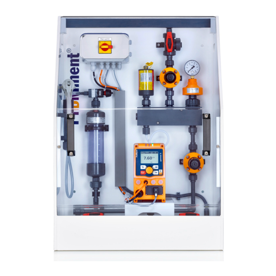
Universal Metering System DSUa Mini
Metering frame complete with all pipework
EN
A2700
Please carefully read these operating instructions before use. · Do not discard.
The operator shall be liable for any damage caused by installation or operating errors.
The latest version of the operating instructions are available on our homepage.
982011
Original operating instructions (2006/42/EC)
Version: BA DST 012 02/19 EN
Advertisement
Table of Contents
Troubleshooting

Related Manuals for ProMinent DULCODOS universal mini


Summary of Contents for ProMinent DULCODOS universal mini
- Page 1 Assembly and operating instructions Universal Metering System DSUa Mini Metering frame complete with all pipework A2700 Please carefully read these operating instructions before use. · Do not discard. The operator shall be liable for any damage caused by installation or operating errors. The latest version of the operating instructions are available on our homepage.
- Page 2 Supplemental directives General non-discriminatory approach In order to make it easier to read, this document uses the male form in grammatical structures but with an implied neutral sense. It is aimed equally at both men and women. We kindly ask female readers for their understanding in this simplification of the text.
-
Page 3: Table Of Contents
Table of contents Table of contents About this product..............4 1.1 Technical details............4 1.2 Identity code..............5 1.3 Metering system, 1 pump, 1 point of injection....9 1.4 Metering system, 2 pumps, 1 point of injection... 10 1.5 Metering system, 2 pumps, 2 points of injection..11 Safety and responsibility............. -
Page 4: About This Product
About this product About this product 1.1 Technical details The metering system DULCODOS ® universal combines standard components with the solenoid-driven metering pump you have selected. For the reliable metering of liquid chemicals. Technical details: Solenoid-driven metering pumps Beta ® delta ®... -
Page 5: Identity Code
About this product 1.2 Identity code DSUa DULCODOS universal mini Pipework / Seal / Function PVC, EPDM, for 1 pump and 1 point of injection PVC, EPDM, for 2 pumps and 1 point of injection PVC, EPDM, for 2 pumps and 2 points of injection... - Page 6 About this product DSUa DULCODOS universal mini Splash guard for (C/F) Stainless steel bracket No stainless steel bracket Stainless steel bracket (H= 150 mm) + machine feet for (A/D) Stainless steel bracket (H= 150 mm) + machine feet for (B/E)
- Page 7 About this product DSUa DULCODOS universal mini Beta ® 10 bar / 0.74 l/h, BT4b 1000 PVT, 6x4 16 bar / 2.2 l/h, BT4b 1602 PVT, 6x4 16 bar / 3.60 l/h, BT4b 1604 PVT, 6x4 7 bar / 7.10 l/h, BT4b 0708 PVT, 8x5 4 bar / 12.30 l/h, BT4b 0413 PVT, 8x5...
- Page 8 About this product DSUa DULCODOS universal mini Certification CE certification...
-
Page 9: Metering System, 1 Pump, 1 Point Of Injection
About this product 1.3 Metering system, 1 pump, 1 point of injection A2699 Fig. 2: Metering system, 1 pump, 1 point of injection, all dimensions in mm Feed Outlet Drain Not shown Connecting parts for flushing pipe DN10, 2 no. Name Material/type Dimension... -
Page 10: Metering System, 2 Pumps, 1 Point Of Injection
About this product Name Material/type Dimension Material Quan‐ Part number tity Terminal box 180x110x90 mm - 1036995 3-way ball valve DN10 PVC-U 1043568 1.4 Metering system, 2 pumps, 1 point of injection A2701 Fig. 3: Metering system, 2 pumps, 1 point of injection Feed Outlet Drain... -
Page 11: Metering System, 2 Pumps, 2 Points Of Injection
About this product Name Material/type Dimension Material Quan‐ Part number tity DHV-U DN10 PVC-U 1037765 Back pressure DHV-U DN10 PVC-U 1037765 valve Vacuum pump MI8121 1031565 Hubinont ® Vacuum cylinder DN10 PVC-U 1025699 Ball valve DN10 PVC-U 1024538 Level switch PP1/PE 142086 Splash guard... - Page 12 About this product Name Material/type Dimension Material Quan‐ Part number tity Assembly frame 700x1000x400 Metering pump To be selected by the customer. Pulsation damper 0.09 litres PVC-U 1057944 Hidracar ® U001 Manometer MDM902 d25 / G1/4" PVC-U 1030362 DHV-U DN10 PVC-U 1037765 Back pressure...
-
Page 13: Safety And Responsibility
Safety and responsibility Safety and responsibility 2.1 User qualification WARNING! Danger of injury with inadequately qualified per‐ sonnel The operator of the system / equipment is respon‐ sible for ensuring that the qualifications are ful‐ filled. If inadequately qualified personnel work on the unit or loiter in the hazard zone of the unit, this could result in dangers that could cause serious injuries and material damage. -
Page 14: Labelling Of Warning Information
Safety and responsibility 2.2 Labelling of Warning Information Introduction These operating instructions provide information on the technical data and functions of the product. These operating instructions pro‐ vide detailed warning information and are provided as clear step- by-step instructions. The warning information and notes are categorised according to the following scheme. -
Page 15: General Safety Notes
Safety and responsibility Type of information Hints on use and additional information. Source of the information. Additional measures. Denotes hints on use and other useful informa‐ – tion. It does not indicate a hazardous or dam‐ aging situation. 2.3 General safety notes WARNING! Danger from hazardous substances! Possible consequence: Fatal or very serious inju‐... - Page 16 Safety and responsibility WARNING! Operating error / Unauthorised access Possible consequence: Fatal or very serious inju‐ ries. – Measure: Ensure that there can be no unau‐ thorised access to the device – Ensure that the device is only operated by ade‐ quately qualified and technically expert per‐...
- Page 17 Safety and responsibility CAUTION! Caution: backflow Metering pumps are not absolutely leak-tight shut- off devices. Use a shut-off valve, a solenoid valve or a vacuum breaker as an absolutely leak-tight shut-off device. CAUTION! Personnel injury and material damage / Unit starts immediately The pump can start to pump as soon as it is con‐...
-
Page 18: Intended Use
Safety and responsibility 2.4 Intended Use Intended Use Only use the metering system to meter liquid feed chemicals into hydraulic systems. The metering system is not intended for the metering of gaseous or solid media. Only use the metering system in accordance with the technical data and specifications provided in these operating instructions and in the operating instructions for the individual components (such as... -
Page 19: Storage And Transport
Storage and Transport Storage and Transport Ä Chapter 2.1 ‘User User qualification: instructed user, see qualification’ on page 13 WARNING! Danger from hazardous substances! Possible consequence: Fatal or very serious inju‐ ries. Please ensure when handling hazardous sub‐ stances that you have read the latest safety data sheets provided by the manufacture of the haz‐... -
Page 20: Assembly And Installation
Hydraulic installation: When installing the metering system, always make sure that the connectors on site are connected to the metering system free of tension. Only use materials that comply with the provisions and speci‐ fications of the ProMinent resistance list. -
Page 21: Installation On The Floor
Assembly and installation Electrical installation: WARNING! Live parts Cause: All work or installation work performed can lead to danger from electrical current. Possible consequence: Fatal or very serious inju‐ ries. Measure: Carry out all work in line with the appli‐ cable national and international statutory regula‐... -
Page 22: Installation With Stainless Steel Bracket
Assembly and installation 4.3 Installation with stainless steel bracket 4 x M8 machine feet with fixing hole Ø15 mm 1 x stainless steel bracket 1190x600x100 mm (LxHxW) 4 x M8 fixing bolts (bracket – mounting frame) A2353 Fig. 6: Installation with stainless steel bracket 4.4 Installation on the wall 4 x M8 bolts A2704... -
Page 23: Connect The Suction Lance Level Gauge
Assembly and installation 4.5 Connect the suction lance level gauge Model: 1 pump, 1 point of injection Connect the level switch to the pump. Model: 2 pumps, 1 point of injection Connect the level switch to the active pump. Model: 2 pumps, 2 points of injection Connect the level switch to the terminal box. -
Page 24: Commissioning
Commissioning Commissioning Ä Chapter 2.1 ‘User quali‐ User qualification: trained user, see fication’ on page 13 Prerequisite for commissioning: All installation and assembly work has been per‐ formed by qualified personnel. The system operator has produced system-specific operating guidelines and has trained the operating personnel on the basis of these operating guide‐... -
Page 25: Personal Protective Equipment (Ppe)
Commissioning 5.2 Personal Protective Equipment (PPE) WARNING! Danger from hazardous substances! Possible consequence: Fatal or very serious inju‐ ries. Please ensure when handling hazardous sub‐ stances that you have read the latest safety data sheets provided by the manufacture of the haz‐ ardous substance. -
Page 26: Connecting The Chemical Tank For Commissioning
Commissioning Run the metering pump for a few minutes to allow all air bub‐ bles to escape from the metering system. Set the pump to the required metering volume. You can adjust the pump output by changing the stroke rate and stroke length. ð... -
Page 27: Operation Of The Metering System
Operation of the Metering System Operation of the Metering System Ä Chapter 2.1 ‘User User qualification: instructed user, see qualification’ on page 13 WARNING! Danger from hazardous substances! Possible consequence: Fatal or very serious inju‐ ries. Please ensure when handling hazardous sub‐ stances that you have read the latest safety data sheets provided by the manufacture of the haz‐... -
Page 28: Maintenance And Troubleshooting
Maintenance and Troubleshooting Maintenance and Troubleshooting Ä Chapter 2.1 ‘User quali‐ User qualification: trained user, see fication’ on page 13 WARNING! Danger from hazardous substances! Possible consequence: Fatal or very serious inju‐ ries. Please ensure when handling hazardous sub‐ stances that you have read the latest safety data sheets provided by the manufacture of the haz‐... -
Page 29: Maintenance
Maintenance and Troubleshooting 7.1 Maintenance Maintenance intervals Maintenance intervals strongly depend on the feed chemical, the hydraulic conditions and the effective run-time of the components. No general statement on maintenance intervals can therefore be pro‐ vided. The maintenance intervals recommended and specified in the operating instructions are based on many years of experience. - Page 30 Maintenance and Troubleshooting Tab. 2: "Maintenance" schedule for the metering system. What? Where? Where described? Metering pumps Functional test Daily inspection Pump operating instruc‐ tions Inspection of the electrical connec‐ Quarterly inspection Metering system operating tions, mechanical intactness, secure instructions fixing and corrosion damage Check the starting torques of the 24 hours after initial commissioning,...
-
Page 31: Troubleshooting
Maintenance and Troubleshooting 7.2 Troubleshooting Fault Possible cause Remedy Suction line contains gas Priming lift too high, operating condi‐ Reduce priming lift, use automatic bubbles tions too close to the vapour pressure gas release, reduce temperature of the medium Suction line leaks and is drawing air Check negative pressure tightness and connections, bleed line Medium tends to be gaseous... - Page 32 Maintenance and Troubleshooting Fault Possible cause Remedy Back pressure too high at the injection Reduce back pressure or replace point pump with a higher capacity Injection point blocked Clean injection point Voltage drop or failure Reconnect the power supply Cable for power supply is not correctly Ensure correct power supply through connected measurement...
-
Page 33: Decommissioning And Disposal
Decommissioning and disposal Decommissioning and disposal Ä Chapter 2.1 ‘User User qualification: instructed user, see qualification’ on page 13 WARNING! Danger from hazardous substances! Possible consequence: Fatal or very serious inju‐ ries. Please ensure when handling hazardous sub‐ stances that you have read the latest safety data sheets provided by the manufacture of the haz‐... -
Page 34: Disposal Of Used Parts
Refer to the Material Safety Data Sheet for your feed chemical. A current Declaration of Decontamination is available to download on the ProMinent website. Sign indicating EU collection system In accordance with the European Directive 2012/19/EU on waste electrical and electronic equipment, this device features the symbol showing a waste bin with a line through it. -
Page 35: Technical Data
Technical data Technical data DSUa: 1 pump, 1 point of injection 2 pumps, 1 point of injection Dimensions HxWxD (mm) 850x600x410 1000x700x410 Weight without pump(s) 30 kg 45 kg Weight with pump(s) 45 kg 65 kg Storage and transport temperature 0 °C ... - Page 36 Technical data DSUa: 2 pumps, 2 points of injection Dimensions HxWxD (mm) 850x900x410 Weight without pumps 50 kg Weight with pumps 70 kg Storage and transport temperature 0 °C ... +50 °C Operation temperature 0 °C ... +40 °C Installation site Indoors Maximum relative air humidity <...
-
Page 37: Drawings
Drawings Drawings 10.1 Metering system, 1 pump, 1 point of injection A2708 Fig. 8: Metering system, 1 pump, 1 point of injection... -
Page 38: Metering System, 2 Pumps, 1 Point Of Injection
Drawings 10.2 Metering system, 2 pumps, 1 point of injection A2709 Fig. 9: Metering system, 2 pumps, 1 point of injection... -
Page 39: Metering System, 2 Pumps, 2 Points Of Injection
Drawings 10.3 Metering system, 2 pumps, 2 points of injection Fig. 10: Metering system, 2 pumps, 2 points of injection... -
Page 40: Flow Diagram Of Dsua Mini (Pid)
Flow diagram of DSUa mini (PID) Flow diagram of DSUa mini (PID) 11.1 Legend for flow diagrams Symbols Process line symbols Test valve Main process line Ball valve Back pressure valve Pulsation damper Calibration pot Pressure display Metering pump A2428 Fig. -
Page 41: Flow Diagram Of Dsua Mini 1 (Pid)
Flow diagram of DSUa mini (PID) 11.2 Flow diagram of DSUa mini 1 (PID) A2705 Fig. 12: Flow diagram of DSUa mini 1 (PID) -
Page 42: Flow Diagram Of Dsua Mini 2 (Pid)
Flow diagram of DSUa mini (PID) 11.3 Flow diagram of DSUa mini 2 (PID) A2706 Fig. 13: Flow diagram of DSUa mini 2 (PID) -
Page 43: Flow Diagram Of Dsua Mini 3 (Pid)
Flow diagram of DSUa mini (PID) 11.4 Flow diagram of DSUa mini 3 (PID) A2707 Fig. 14: Flow diagram of DSUa mini 3 (PID) -
Page 44: Electrical Wiring Diagram
Electrical wiring diagram Electrical wiring diagram 12.1 Electrical Wiring Diagram, 1062129, 1 Pump Fig. 15: BT4b, BT5b... - Page 45 Electrical wiring diagram Fig. 16: DLTa, GMXa...
-
Page 46: Electrical Wiring Diagram, 2 Pumps
Electrical wiring diagram 12.2 Electrical wiring diagram, 2 pumps A2711 Fig. 17: Electrical wiring diagram, 2 pumps... - Page 47 Electrical wiring diagram A2712 Fig. 18: Electrical wiring diagram, 2 pumps...
-
Page 48: Declaration Of Conformity For Machinery
Declaration of Conformity for Machinery In accordance with DIRECTIVE 2006/42/EC OF THE EUROPEAN PARLIAMENT AND OF THE COUNCIL, Appendix I, BASIC HEALTH AND SAFETY REQUIREMENTS, section 1.7.4.2. C. ProMinent Systems s.r.o. Fügnerova ul. 567 CZ- 336 01 Blovice, Czech Republic IČ: 48363448... -
Page 49: Index
Index Index Action, step by step ......2 Personal protective equipment (PPE) ..25 Applied harmonised standards . - Page 52 ProMinent GmbH Im Schuhmachergewann 5 - 11 69123 Heidelberg, Germany Telephone: +49 6221 842-0 Fax: +49 6221 842-419 Email: info@prominent.com Internet: www.prominent.com 982011, 1, en_GB © 2019...
Need help?
Do you have a question about the DULCODOS universal mini and is the answer not in the manual?
Questions and answers