Table of Contents
Advertisement
Operating Instructions
Two-wire measurement transmitter
®
DULCOMETER
DMT
Measured variable Conductivity
___ ___ ___ ___ ___ ___ ___ ___ ___ ___ ___ ___
DMTa
Please enter the identity code for your device here!
Please carefully read through these operating instructions in full before
commissioning this equipment! · Do not discard!
The operator shall be liable for any damage caused by installation or operating errors!
Part No. 987636
ProMinent Dosiertechnik GmbH · 69123 Heidelberg · F. R. Germany
BA DM 180 04/10 EN
Advertisement
Table of Contents

Subscribe to Our Youtube Channel
Related Manuals for ProMinent DULCOMETER DMT Series


Summary of Contents for ProMinent DULCOMETER DMT Series
- Page 1 Please carefully read through these operating instructions in full before commissioning this equipment! · Do not discard! The operator shall be liable for any damage caused by installation or operating errors! Part No. 987636 ProMinent Dosiertechnik GmbH · 69123 Heidelberg · F. R. Germany BA DM 180 04/10 EN...
- Page 2 Legal Notice Legal notice: Operating Instructions ® Two-wire measurement transmitter DULCOMETER Measured variable Conductivity © ProMinent Dosiertechnik GmbH, 1999 Address: ProMinent Dosiertechnik GmbH Im Schuhmachergewann 5-11 69123 Heidelberg Germany Telefon: +49 6221 842-0 Fax: +49 6221 842-419 info@prominent.com www.prominent.com Subject to technical alterations.
-
Page 3: Table Of Contents
12 Technical Data ................13 Replacement Parts and Accessories ....Appendix EC Declaration of Conformity ........... Terminal Connection Diagram ..........Wiring example - two wire system ........® PROFIBUS circuit board terminal connection ... Index ......................Drilling template ProMinent ®... -
Page 4: Device Identification/Identity Code
DMTa DMT series DULCOMETER measurement transmitter Assembly type Wall mounted Control panel mounted (not PROFIBUS ® -DMT) Version with ProMinent logo None Electrical connection 4-20 mA 2-wire ® PROFIBUS -DP, 24 V DC (16...30 V DC) Communication interface None ®... -
Page 5: General Guidelines For Use
Notes are intended to make your work easier. and safety instructions: CAUTION Describes a potentially dangerous situation. Could result in personal injuries or damage to property if not observed. IMPORTANT Describes a potentially damaging situation. Could result in damage to property if not observed. ProMinent ®... -
Page 6: Safety
(extra covering, weather-proof lid)! The housing may be affected by direct sunlight! Enclosure Ratings Enclosure ratings When assembly is carried out correctly the following enclosure ratings apply: • Wall/pipe mounted version: IP 65 • Control panel mounted version: IP 54 ProMinent ®... -
Page 7: Storage/Transport
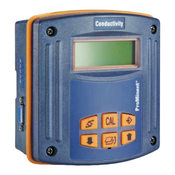
Ambient conditions for storage and transport: Temperature: -20 ºC to 70 ºC Humidity: < 95 % relative humidity, non-condensing Device Overview/Operating Elements Measured variable Fig. 1 LCD-Display „CAL“ key „Change“ key „Enter“ key „Back“ key „Up“ key „Down“ key 3456_4 ProMinent ®... -
Page 8: Function Description
Block circuit diagram EEPROM (parameter memory) Measured variable FlashROM µP Temperature (program memory) Signal output 4 ... 20 mA Power supply, current control 16 ... 40 V DC and/or 30 V DC (PROFIBUS ® Keypad LC display variant) ProMinent ®... -
Page 9: Key Functions
"CAL" key open a calibration menu from open a calibration menu, a permanent display if available "Up/down" keys alter contrast from the change a value permanent display ProMinent ®... -
Page 10: Operating Menu, Schematic
• The display will automatically return to permanent display if you do not press a key within 5 min. (does not save changes to values). ProMinent ®... - Page 11 Holding the key down for longer alters numerical values increasingly rapidly. Use the enter key to save changed values in the menu option. You will then automatically enter the next info display or (if available) the next menu option. ProMinent ®...
-
Page 12: Assembly/Installation
The DMT is designed for mounting onto a wall or pipe or into a control panel. 6.1.1 Wall Mounting Mounting fittings: 1x wall/pipe bracket 2x round head screw 5x45 mm 2x washer 5.3 2x plug Ø 8 mm, synthetic 1x rubber cap Fig. 2 3515_4 ProMinent ®... - Page 13 ➤ Now tighten the locking screw for added security. Fig. 3 3461_4 ProMinent ®...
- Page 14 Please observe the following steps when mounting onto a pipe: ➤ Fix the wall/pipe bracket in place using the cable connectors or hose clamps, see fig. 4 ➤ Proceed as described under 6.1.1 Wall Mounting Fig. 4 3464_4 ProMinent ®...
- Page 15 ➤ Drill the 4 screw holes with a 3.5 mm Ø drill ➤ Pierce out the cut-out with a keyhole saw, or if this is not to be pierced out, drill the 4 holes in the cut-out area with a 8 mm Ø drill. Fig. 5 3463_3 ProMinent ®...
-
Page 16: Installation (Electrical)
Very strong interference can lead to incorrect functioning of the DMT or irreparable damage! • The hinge between the front and back sections of the housing cannot withstand mechanical loads! When working on the front section it must be held safely! ProMinent ®... - Page 17 (e.g. Pt 1000). Fig. 6 ➤ Screw on the corresponding PG threaded connectors (fig. 7, ➀) and tighten (not locking screws). ➤ Insert reducers (fig. 7, ➁) as required for the diameter of the cable into the PG threaded connectors. ProMinent ®...
- Page 18 (If necessary, pull the front section forward a little in order to relieve stress on the seal.) ➤ Fasten the housing screws fingertight Fig. 7 3465_3 6.2.2 Pipe Mounted Version See 6.2.1 Wall Mounting ProMinent ®...
- Page 19 . If the display is too dark, increase the brightness using the down arrow key Fig. 8 and Fig. 9 current b voltage b voltage a 4 to 20 mA + current a – Pt 1000 / Pt 100 3459_4 ProMinent ®...
-
Page 20: Configuring The Dmt
4 mA = 0.00 µS/cm param. output output: meas. value 20 mA = 20.00 µS/cm 4 mA: 0.00 µS/cm 20 mA: 20.00 µS/cm general settings general settings general settings DMTAW091L10E0000 language change DMTAW091L10E0000 access code = 5000 2.1.02 english free access ProMinent ®... -
Page 21: Parameters Temperature
7.1.2 General setting: Temperature measurement = manual (pH only) param. temperature T = 22.6 ˚C input: manual unit: ˚C unit: ˚C ➤ Enter the process temperature under “T”. ➤ Select the temperature unit °C or °F under “unit”. ProMinent ®... - Page 22 ➤ Enter the process temperature under “T”. ➤ Select the temperature unit °C or °F under “unit”. 7.1.4 General setting: Temperature measurement = none No info display appears in the operating menu. No temperature measurement is carried out. ProMinent ®...
-
Page 23: Conductivity Sensor Connection
(2-wire or 4-wire connection) NOTE You need to enter the sensor cable resistance only if you: • have a sensor with 2-wire connector cable longer than 20 m • are measuring above 10 mS/cm. ProMinent ®... -
Page 24: Parameter Measurement
➤ Enter the cell constant under "cell const." ➤ Enter the temperature coefficient α under "t.coeff." If the value of the temperature coefficient α is not known then please proceed with setting as follows: ➤ Select the value “t.coef.“ with the change key ProMinent ®... -
Page 25: Parameter Output
(= 1 in the identity code) param. output I = 10.2 mA output: constant I = 10.2 mA ➤ Under “l”, enter an output current between 4 and 20 mA. This setting is used for the function check. ProMinent ®... - Page 26 The DMT emits a constant output current of 4 mA. This setting is used for the function check and/or is selected if the DMT is to be used purely as a display device (the power consumption is minimal in this case). ProMinent ®...
-
Page 27: General Settings
This code can be changed in the third menu option “change access code”. Use the change key to move to individual digits. The new code is confirmed and activated with the enter key ProMinent ®... -
Page 28: Operation
2 (Calibration of Conductivity Measurement input menu is accessed) ➤ Press the enter key (menu options accessed) ➤ Place the DMT conductivity sensor and the temperature gauge in the buffer solution and wait until measured variables are stable ProMinent ®... - Page 29 • Your settings become effective the moment you press the enter key. • If there is a significant discrepancy between the measured variable from your reference measuring device and the DMT it is advisable to seek the cause! ProMinent ®...
-
Page 30: Trouble Shooting
Error text: “temp. input error“ + Measured value 999.0 Error Reason Remedy No signal at No sensor connected Connect sensor or set temperature input temperature manually Break in sensor cable Replace sensor cable ProMinent ®... -
Page 31: Maintenance/Repair
Dry afterwards. IMPORTANT Never use solvents! May corrode the surface! Repair Please return the DMT to us for repairs. Disposal IMPORTANT Electronic waste is subject to rules for special waste! Observe all currently applicable local and national regulations! ProMinent ®... -
Page 32: Technical Data
0.01… 200 µS/cm 0.1… 2 mS/cm 1…20 mS/cm 10…200 mS/cm depending on sensor type used, the measurement range can be increased to 200 mS/cm depending on sensor type used, the measurement range can be increased to 2 S/cm ProMinent ®... -
Page 33: Replacement Parts And Accessories
Luranyl PPE - GF 10 - grey RAL 7035 Keypad: Slicon Housing seal: Silicon Replacement Parts and Accessories Assembly set for wall/pipe assembly part number 1003205 Hose clamp for pillar mounting part number 1002777 Sensor see product catalogue Sensor cable see product catalogue ProMinent ®... -
Page 34: Ec Declaration Of Conformity
EC Declaration of Conformity ProMinent ®... -
Page 35: Terminal Connection Diagram
Terminal Connection Diagram ProMinent ®... -
Page 36: Wiring Example - Two Wire System
• Take into account the sum of the ohmic resistances of all devices in the current loop (excluding power supply). The input voltage of the transmitter must never drop below 16 V during operation. The measured value will otherwise be wrong. ProMinent ®... -
Page 37: Profibus ® Circuit Board Terminal Connection
(plug in the connector on the ® side of the PROFIBUS circuit board with the red edge of the ribbon cable facing upwards, see fig.). Briefly disconnect from the power supply. ProMinent ®... -
Page 38: Index
DMT 19, 35 PROFIBUS ® circuit board 37 Trouble shooting 30 Two wire system 36 Language 27 LC display brightness 28 Wiring example - two wire system 36 Menu option 11 Menu overview 20 Minimum current use 26 Mounting 12 ProMinent ®... -
Page 39: Drilling Template
Drilling template ® DULCOMETER Drilling template for control panel assembly NOTE: Check the measurements of the drilling/stamping template! ProMinent ®... - Page 40 Addresses and delivery information from the manufacturer: ProMinent Dosiertechnik GmbH Im Schuhmachergewann 5-11 69123 Heidelberg · Germany Tel.: +49 6221 842-0 Fax: +49 6221 842-419 info@prominent.com www.prominent.com ProMinent ®...
Need help?
Do you have a question about the DULCOMETER DMT Series and is the answer not in the manual?
Questions and answers