ProMinent DULCO flex Control Operating Instructions Manual
Peristaltic metering pump
Hide thumbs
Also See for DULCO flex Control:
- Operating instructions manual (120 pages) ,
- Original operating instructions (76 pages) ,
- Installation and configuration manual (16 pages)
Table of Contents
Advertisement
Quick Links
Operating instructions
Peristaltic metering pump
DULCO flex Control, DFXa
EN
Please carefully read these operating instructions before use. · Do not discard.
The operator shall be liable for any damage caused by installation or operating errors.
The latest version of the operating instructions are available on our homepage.
Part no. 981953
Original operating instructions (2006/42/EC)
BA DX 031 04/21 EN
Advertisement
Table of Contents

Related Manuals for ProMinent DULCO flex Control


Summary of Contents for ProMinent DULCO flex Control
- Page 1 Operating instructions Peristaltic metering pump DULCO flex Control, DFXa Please carefully read these operating instructions before use. · Do not discard. The operator shall be liable for any damage caused by installation or operating errors. The latest version of the operating instructions are available on our homepage.
- Page 2 Supplemental directives Supplementary information Read the following supplementary information in its entirety! You will ben‐ efit more from the operating instructions should you already know this information. The following are highlighted separately in the document: Enumerated lists Fig. 1: Please read! Instructions ð...
-
Page 3: Table Of Contents
Table of contents Table of contents Identity code..................6 About this pump................9 Safety chapter................10 Storage, transport and unpacking..........15 Overview of equipment and control elements....... 16 5.1 Overview of equipment............16 5.2 Control elements..............17 5.2.1 Control elements..............17 5.2.2 Key functions.............. - Page 4 Diagrams for adjusting the pump capacity........97 Declaration of Conformity for Machinery........98 UK Declaration of Conformity............99 Operating / set-up overview DULCO flex Control - DFXa... 100 DULCO flex Control - DFXa operating menu, overall....102 Continuous displays and secondary displays......107...
- Page 5 Table of contents Installation instructions for retrofitting relays....... 109 Index.................... 111...
-
Page 6: Identity Code
Identity code Identity code Product identification This identity code serves to identify the product. Use the identity code from the Product Catalogue for orders. Product range DULCO flex Control - DFXa DFXa Regional design Europe CN China Pump type 0518... - Page 7 Identity code Product range DULCO flex Control - DFXa 2 Housing RAL5003 / hood RAL3001 M modified Logo with ProMinent logo without ProMinent logo Design of power unit U 100-240 V Cable and plug A 2 m, Europe B 2 m, Switzerland...
- Page 8 Identity code Product range DULCO flex Control - DFXa German English Spanish French...
-
Page 9: About This Pump
About this pump About this pump About this pump Pumps in the DULCO flex Control - DFXa product range are microproc‐ essor-controlled peristaltic metering pumps with the following characteris‐ tics: Simple adjustment of the dosing rate directly in l/h or in gph... -
Page 10: Safety Chapter
Observe the general limitations with regard to viscosity limits, chem‐ ical resistance and density - see also ProMinent Resistance List in the product catalogue or at www.prominent.com! Use the "Resistance List for DULCO flex Control DFXa and DFYa” available at www.promi‐... - Page 11 Safety chapter Safety information WARNING! Warning about personal and material damage The pump can start to pump, as soon as it is connected to the mains voltage. – Install an emergency cut-off switch in the pump power supply line or integrate the pump in the emer‐ gency cut-off management of the system.
- Page 12 An unsuitable feed chemical may cause premature wear of the pump tube. – Pay attention to the resistance of the pump tube and the "Resistance List for DULCO flex Control DFXa and DFYa” available at www.prominent.com when selecting the feed chemical. CAUTION!
- Page 13 Customers should only remove the bearing cover for the liquid end in accordance with the “Repair” chapter. Only ProMinent Service is authorised to open the housing and hood (housing the control elements). Other protective equipment...
- Page 14 Service The service department refers to service technicians, who have received proven training and have been authorised by ProMinent to work on the device / system. Sound pressure level Sound pressure level LpA < 70 dB according to EN ISO 20361...
-
Page 15: Storage, Transport And Unpacking
Storage, transport and unpacking Storage, transport and unpacking Ä ‘Qualification of personnel’ User qualification: Instructed person - see on page 13 Safety information WARNING! Only return metering pumps for repair in a cleaned state and with a flushed liquid end - refer to "Decommis‐ sioning! Only return metering pumps with a completed Decon‐... -
Page 16: Overview Of Equipment And Control Elements
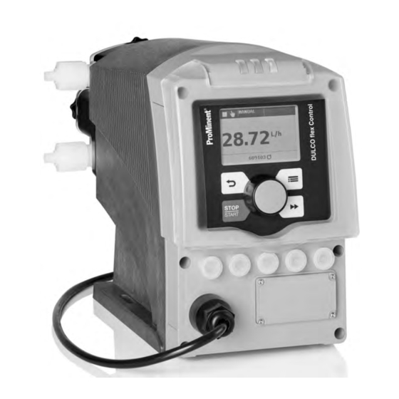
Overview of equipment and control elements Overview of equipment and control elements 5.1 Overview of equipment P_G_0103_SW Fig. 2: Overview of equipment DFXa, complete Control unit Drive unit Liquid end P DX 0177 SW_2 Fig. 3: Liquid end DFXa Dosing head Pressure connector (delivery status) Suction connector (delivery status) Domed nut on star-shaped screw... -
Page 17: Control Elements
Overview of equipment and control elements 5.2 Control elements Control elements, overview P_G_0105_SW 10 11 Fig. 4 LCD screen [Menu] key Clickwheel [Priming] key [STOP/START] key [Back] key Fault indicator (red) Warning indicator (yellow) Operating indicator (green) 10 "Config I/O” terminal 11 "Hose rupture indicator"... - Page 18 Overview of equipment and control elements Identifier and fault displays on the LCD screen ANALOG 4..20mA 10.0 10.0 mA B1150 Fig. 5: Structure of continuous display Status bar Continuous display, central area Secondary display Refer to the chapter entitled "Main displays and secondary displays" in the Appendix for the different main displays and secondary displays.
-
Page 19: Key Functions
Overview of equipment and control elements Identifier Meaning Only with ‘Access protection’ : the pump software is locked. ‘AUX’ The pump is currently pumping at auxiliary capacity. ‘memory’ ‘CONTACT’ and ‘BATCH’ operating modes: Only in the auxiliary function "Memory" has been set. ‘ANALOG’... - Page 20 Overview of equipment and control elements * When priming the pump does not run at maximum number of revolutions. [Priming] is pressed in ‘Stop’ state, then [Priming] has top priority as long as the button is pressed. Refer to the "Set-up basics" chapter for how to adjust fig‐ ures...
-
Page 21: Functional Description
Functional description Functional description 6.1 Unit An electric motor drives a rotor. Rollers are fitted to the ends of the rotors, which press the pump tube against the inner curvature of the dosing head. The peristaltic pump operates by the rollers driving the feed chemical through the pump tube. -
Page 22: Relays (Options)
Functional description "Calibrate" function Calibrate the pump if you wish good precision when metering high-vis‐ cosity feed chemicals. ‘menu’ "Auxiliary capacity” function This facilitates the switch-over to a fixed adjustable capacity in the via the "External control" socket. "Timer" function This permits a simple timer program to be set up without the need for an additional timer module. -
Page 23: Hierarchy Of Operating Modes, Functions And Fault Statuses
Functional description LED display Colour lights up flashes Operating display green The pump is ready for operation During every revolution: dosing rate greater than 10 l / h During every 1/2 revolu‐ tion: dosing rate less than 10 l / h During every 1/8 revolu‐... -
Page 24: Assembly
User qualification: technical personnel and service - see personnel’ on page 13 Refer to the correct dimensional drawings for the pump from the online version of the operating instructions on our website. www.prominent.com Compare the dimensions on the dimensional drawing with those of the pump. CAUTION! Danger from incorrectly operated or inadequately main‐... - Page 25 Assembly P_DX_0181_SW Fig. 8 Ensure that the system is at atmospheric pressure. Adhere to the material safety data sheet for the feed chemical. Prevent the escape of feed chemical. If necessary take protective measures. [STOP/START] to bring the pump to a stop (manually). Press Empty the liquid end (turn the liquid end upside down and allow the feed chemical to run out;...
- Page 26 Assembly Place the 2nd half of the rotor (5) on the drive axle in the dosing head with "This side DOWN" surface facing downwards - the rollers must point towards the recesses for the hydraulic connectors. Insert the tube (4) into the dosing head (5) and snap the two hydraulic connectors into place - round side in the dosing head (5).
-
Page 27: Installation, Hydraulic
– Take into account the resistance of the wetted mate‐ rials and the ProMinent Resistance List when selecting the feed chemical - see the ProMinent Product Catalogue or visit ProMinent. CAUTION! Warning of feed chemical spraying around An unsuitable feed chemical may cause premature wear of the pump tube. - Page 28 Installation, hydraulic CAUTION! Warning of feed chemical spraying around The pipes can become loose or rupture if they are not installed correctly. – Route all tube lines so they are free from mechan‐ ical stresses and kinks. – Only use original tubes with the specified tube dimensions and wall thicknesses.
- Page 29 Installation, hydraulic Tighten the union nuts. If you are only using a tube line and not a suction lance: shorten the free end of the suction line so that the end of the suction line hangs just above the base of the feed chemical tank.
-
Page 30: Installation, Electrical
Installation, electrical Installation, electrical Ä ‘Qualification of personnel’ User qualification: electrical technician - see on page 13 WARNING! Danger of electric shock A mains voltage may exist inside the device. – Before any work, disconnect the device's mains cable from the mains. WARNING! Risk of electric shock This pump is supplied with a grounding conductor and a... -
Page 31: Supply Voltage Connector - Mains Voltage
Installation, electrical CAUTION! Material damage possible due to power surges Should the pump be connected to the mains power supply in parallel to inductive consumers (such as sole‐ noid valves, motors), inductive power surges can damage the control when it is switched off. –... -
Page 32: Description Of The Terminals
Installation, electrical Simply disconnect the pump from the mains/power supply for repair or maintenance work, among other things. With cables with plug: Provide adequate room – around the socket provided. With cables without plug: Provide an appropriate, – easily accessible On/Off switching option in your building installation. -
Page 33: External Control" Terminal
Installation, electrical Tab. 3: Control via: Switching element Specification Potential-free contact Load: 0.5 mA at 5 V Semiconductor switch Residual voltage < 2 V Configured as an output Parameter Value Max. pulse frequency 50 pulses/s Min. pulse duration 10 ms Switching element Specification NPN output (Open Drain) -
Page 34: Level Switch" Terminal
Installation, electrical Function 5-wire cable 2-wire cable Pause brown bridged at pin 4 External contact white brown mA input* blue Earth GND black white P_BE_0015_SW Auxiliary capacity grey Fig. 13: Assignment on the cable * with identity code characteristic “Control version”: 3 Refer to the functional description for the sequence of functions and operating modes. -
Page 35: Metering Monitor" Terminal
Installation, electrical 9.2.3.1 Suction lance with 2-stage level switch Electrical interface Data Value Unit Voltage with open contacts Input resistance 10 kΩ Control via: potential-free contact (load: 0.5 mA at 5 V) or semiconductor switch (residual voltage < 0.7 V) P_BE_0016_SW Fig. -
Page 36: Relays
Installation, electrical 9.2.6 Relays 9.2.6.1 Relay functions Tab. 4: DULCO flex Control - DFXa DFXa Identity code Designation Type Maximum voltage Maximum current no relay Fault indicating relay Changeover contact 230 V AC Fault indicating relay + Releasing (NC) 24 V DC... - Page 37 Installation, electrical Identity code 1 To pin VDE cable Contact CSA cable white NO (normally open) white green NC (normally closed) brown C (common) black P_G_0072_SW Fig. 19: Assignment on the pump 9.2.6.3 Output for other relays (identity code 4) A fault indicating and a pacing relay can be ordered as options - refer to the ordering information in the appendix.
- Page 38 Installation, electrical The variable to be signalled for the current output can be selected in the ‘ANALOG OUTPUT’ menu. The current output plus relay can be retrofitted and operates once it is plugged into the board. Electrical interface for current output Data Value Unit P_SI_0044...
-
Page 39: Basic Set-Up Principles
Please also refer to all the overviews covering – "Operating/set-up overview" and "Operating menu for DULCO flex Control - DFXa, complete" in the appendix and the "Overview of equipment and con‐ trol elements" and "Control elements” chapters. The pump exits the menu and returns to a contin‐... - Page 40 Basic set-up principles Confirming an entry [Clickwheel] . Briefly press the ð The software switches to the next menu point or back to the menu and saves the entry. Exiting a menu option without confirming it [Back] . Press ð The software switches to the next menu point or back to the menu without saving anything.
-
Page 41: Checking Adjustable Variables
Basic set-up principles Confirming adjustable variables [Clickwheel] 1x. Press the ð The software saves the entry. 10.2 Checking adjustable variables Continuous displays Before adjusting the pump, you can check the current settings of the adjustable variables: [Clickwheel] if the pump is showing a continuous Simply turn the display. -
Page 42: Initial Commissioning
Initial commissioning Initial commissioning Ä ‘Qualification of User qualification: technical personnel and service - see personnel’ on page 13 WARNING! The rotating rotor may catch and trap body parts. – Only use the pump tube in the dosing head as out‐ lined in the instructions provided below. - Page 43 Initial commissioning P_DX_006 9_SW_2 Loosen the 4 star-shaped screws on the dosing head and remove with the bearing cover. Thoroughly grease the pump tube and the running surface with the silicone grease provided. Insert the pump tube into the dosing head. P_DX_006 8_SW Insert the rotor half supplied.
- Page 44 Initial commissioning Press the Clickwheel. ð The rotor turns slowly and the following appears: ‘ Please wait...’ . The rotor stops and ‘Please change the tube!’ appears. Please ignore this. Press the Clickwheel ð The rotor turns slowly and the following appears: ‘...
-
Page 45: Set Up / 'Menu
13 Refer to the overviews covering “Operating/set up – overview” and “Operating menu DULCO flex Control - DFXa, complete” in the appendix and in the “Over‐ view of equipment” - “Control elements” chapters by way of supplementary information. -
Page 46: Operating Mode
‘Menu’ Set up / ‘Operating mode’ 12.2.1 ‘Menu / Information è Settings è Operating mode è ...’ ‘Manual’ 12.2.1.1 ‘Menu / Information è Settings è Operating mode è Manual’ ‘Manual’ operating mode allows you to operate the pump manually. The capacity can be set in the continuous displays of this operating mode. 12.2.1.2 ‘Contact’... - Page 47 ‘Menu’ Set up / ‘Batch’ operating mode enables you to pre-select large metering vol‐ umes or metering times. [Clickwheel] if you have You can trigger the metering volume using the ‘Push’ continuous display. You can also trigger already switched to the them via a pulse using the "External control"...
- Page 48 ‘Menu’ Set up / The "Linear curve" symbol appears on the LCD screen. You can enter any speed behaviour proportional to the current signal. For this purpose, enter any two points P1 (I1, F1) and P2 (I2, F2) (F1 is the speed at which the pump is to operate at current I1, F2 is the speed at which the pump is to operate at current I2...);...
-
Page 49: Dosing Direction
‘Menu’ Set up / I [mA] I [mA] B0089 Fig. 29: Speed-current diagram for a) Lower side band, b) Upper side band ‘Upper side band’ Using this processing type, you can control a metering pump using the current signal as shown in the diagram above. ‘Lower side band’... - Page 50 ‘Menu’ Set up / The "Concentration" continuous display only – appears, if: the pump is calibrated. – the ‘Concentration’ menu was run through in – the operating mode used. and ‘Concentration control’ was switched to – ‘active’ - in the operating mode being used. –...
- Page 51 ‘Menu’ Set up / ‘active’ in the ‘Concentration control’ menu item and press the [Clickwheel] . ‘Main medium flow’ (in the pipework) and then press the Set the [Clickwheel] . ‘Feed chemical mass concentration’ and press the Set the [Clickwheel] . ‘Feed chemical density’...
- Page 52 ‘Menu’ Set up / Procedure CAUTION! The precision of the concentration is strongly dependent – the precision of the metering pump calibration. – the precision of the inputs. Calibrate the metering pump if it is not yet calibrated - see chapter ‘Set up’...
- Page 53 ‘Menu’ Set up / Procedure CAUTION! The precision of the concentration is strongly dependent – the precision of the metering pump calibration. – the precision of the inputs. ‘Set up’ - Calibrate the metering pump if it is not yet calibrated - see ‘Calibration’...
- Page 54 ‘Menu’ Set up / CAUTION! Risk of incorrect concentrations – After adjusting, check whether the concentrations at various flows correspond to the desired result. The prerequisites are that: the flowing medium has the same density as water (1 kg/l ≜ g/cm the mass concentration of the feed chemical is known - see the feed chemical safety data sheet (e.g.
-
Page 55: Calibration
‘Menu’ Set up / You can enter the desired mass concentration using the [Clickwheel] . CAUTION! – Note the decimal point. – The mass concentration is affected by changes to the capacity. – The pump limits the upper value for the mass concentration, because otherwise the incre‐... - Page 56 ‘Menu’ Set up / WARNING! If the feed chemical is hazardous, take appropriate safety precautions when performing the following cali‐ bration instructions. Observe the material safety data sheet for the feed chemical! Please only calibrate using the suction hose – as shown here.
-
Page 57: System
‘Menu’ Set up / 12.2.5 System ‘Menu / Information è Settings è System è ...’ ‘System’ menu is sub-divided into the following sub-menus: ‘Hose type’ ‘Configure dosing head’ ‘Volume unit’ ‘Start behaviour’ 12.2.5.1 Hose type ‘Menu / Information è Settings è System è Hose type è ...’ You need to enter the hose type in the ‘Hose type’... -
Page 58: Config-I/Os
‘Menu’ Set up / ‘Volume unit’ sub-menu. You can select another unit for the volume in the 12.2.5.4 Start behaviour ‘Menu / Information è Settings è System è Start behaviour è ...’ You can specify the start behaviour of the pump once the supply voltage has been switched on in the ‘Behaviour on start’... -
Page 59: Inputs/Outputs
‘Menu’ Set up / Output The pins can be configured as outputs (timer, warning, error, auxiliary, reset direction of rotation, ...). ‘Selective errors’ or ‘Selective warning’ to issue It is also possible to use very specific errors or warnings (diaphragm rupture, defective stroke metering, air in the dosing head, ...). - Page 60 ‘Menu’ Set up / The setting options for the ‘Relay’ function are only available if a relay is fitted. DULCO flex Control, DFXa Tab. 12: Relay, physical and pre-set to ... Identity code specification Relay, physical Pre-set to ... 1 x changeover contact 230 V – 8 A Fault indicating relay, N/C 2 x N/O 24 V –...
-
Page 61: Priming Time
‘Menu’ Set up / ‘mA-Output (optional)’ 12.2.7.4 ‘Menu / Information è Settings è Inputs/outputs è mA-Output ...’ è You can set which current range is to be used at the mA output here. You can then set whether, for example, the current dosing rate (litres / hour) is to be signalled at the mA output and set the desired value for 20 You can also set the state which the mA output is to signal at 23 mA: Passive... -
Page 62: Date
Please first read this chapter completely to gain an overview. You will then understand the timer better when working through the chapter. The timer DULCO flex Control - DFXa can do the following at predefined times and intervals or event-dependent: open / close the relays... -
Page 63: Setting The Timer
‘Menu’ Set up / ‘Activation’ to ‘active’ . To activate the timer, set ‘Timer state’ then displays ð The first line of the timer menu ‘active’ . The timer starts working - the timer identifier is visible in the continuous display. When ‘Activation’... - Page 64 ‘Menu’ Set up / Restriction with day numbers If you wish to start an action on a certain day of each month, note that the timer only permits days 01 - 28. Using Config I/Os If you wish to use Config I/Os as inputs or outputs, you first need to configure them as a ‘Timer input’...
- Page 65 ‘Menu’ Set up / Example Time event (trigger) Action Workdays 1 (Mo-Fr) Time of day 12:00 Manual 20.00 l/h The example means: ‘Manual’ When it is 12:00 on a workday, then the pump is to work in operating mode at 20.00 l/h. Tab.
- Page 66 ‘Menu’ Set up / Example triggering event (trigger) Action Init Relay 2 closed Init Contact The example means: ‘Timer è Activation è active’ As soon as the programme is started (via ‘Init’ sets ‘Relay 2’ to ‘closed’ and the ‘Operating or power supply on), mode’...
- Page 67 ‘Menu’ Set up / 12.4.2.2 1 time event - several actions You can assign 1 time event to several actions. To do so, always use the same cycle and the same switching time! : Example Time event (trigger) Action Workdays 1 (Mo-Fr) Time of day Halt 12:00...
-
Page 68: Clear All
‘Menu’ Set up / The 1st sorting criterion is the type of time event (trigger) (for the Ä Further information on page 65 and Ä Further infor‐ sequence refer to mation on page 66 ). Time-dependent program lines are ordered below each other initially after the Switching point (2nd sorting criterion) then after the length of the Cycle (3rd sorting criterion). - Page 69 ‘Menu’ Set up / Task: Example of "Weekday metering" The pump is to meter 2 litres every half hour every weekday (Mon-Fri) between 8:00 and 11:00. Solution: As you define switching times with the timer, you need to first define the switching points at 08:30, 09:30 and 10:30.
-
Page 70: Timer Information
‘Menu’ Set up / If something has been entered incorrectly: Either press in the current program line and enter – the correct values or search for the program line in ‘CHANGE’ (auto‐ – matic sorting!). Now press the [Clickwheel], allow the program to run through the program lines again and enter the values correctly or use ‘Clear’... -
Page 71: Brief Explanation Of Selected Functions
‘Menu’ Set up / 12.4.7 Brief explanation of selected functions Time event (trigger) An event can be triggered either time-dependent or event-controlled. 1 - Time events (really time-dependent) are processed precisely to the minute. ‘Init’ ) is executed at the start of the program ( ‘Timer 2 - Initialisation ( Activation è... -
Page 72: Access Protection
‘Menu’ Set up / ‘Access protection’ 12.5.1 ‘Menu / Information è Service è Access protection è ...’ You can lock parts of the setting options here. The following locking options are available: Selection Point ① Point ② ‘None’ ‘ Lock menu’ ‘Lock all’... -
Page 73: Hose
‘Menu’ Set up / ‘Number of revolutions’ ‘Volume counter’ (total litres) ‘All’ [Clickwheel] . To clear: exit the menu by briefly pressing the The values have increased since commissioning the pump, the last cali‐ bration or the last deletion. The "Hose service maintenance" counter can only be reset by going to the ‘Tube Service’... -
Page 74: Error Log Book
‘Menu’ Set up / Hose service in Here you can see the number of hours in which the hose is to be replaced. The value displayed depends on the value in ‘Tube interval’ . Revolutions since service Here you can see how many revolutions the pump has performed since its last maintenance. -
Page 75: Spare Parts Kit Number: Xxxxxxx
‘Menu’ Set up / 12.5.8 Spare parts kit number: XXXXXXX ‘Menu / Information è Service Spare parts kit part number: XXXXXXX è ...’ è You can read the order number (part number) of the correct spare parts kit here. ‘Language’ 12.6 ‘Menu / Information è... -
Page 76: Operation
Operation Operation Ä ‘Qualification of personnel’ User qualification: Instructed person - see on page 13 This chapter describes all the operating options in a continuous display (several symbols and the pressure display appear at the top in the black bar) for the trained person at the pump. Please also refer to the "Operating/Setting overview"... - Page 77 Operation Concentration Time Set-up overview DULCO flex Control - DFXa Continuous display Stop/start pump STOP STOP START START Priming Start batch (only in "Batch" operating mode) Acknowledging errors Check adjustable values Changing directly changeable variables Setting mode B0598 Fig. 31: Control options using keys and locking options...
-
Page 78: Maintenance
Maintenance Maintenance Ä ‘Qualification of User qualification: technical personnel and service - see personnel’ on page 13 WARNING! It is mandatory that you read the safety information and specifications in the "Storage, Transport and Unpacking" chapter prior to shipping the pump. CAUTION! Warning of feed chemical spraying around Feed chemical may spray out of the hydraulic compo‐... - Page 79 Maintenance Expected service life of the pump tube Determining the service life of the pump tube When starting to pump, regularly check the pump tube for wear - do this several times a day if necessary. The service life and thus the replacement interval for the pump tube can be deduced from the information and experience collected.
-
Page 80: Repair
WARNING! Danger of electric shock Unauthorised repairs inside the pump may result in an electric shock. For this reason, only allow a ProMinent branch or repre‐ sentative to perform repairs inside the pump, in partic‐ ular the following: – Replacement of damaged mains connection lines –... -
Page 81: Replacing The Pump Tube
Repair 15.1 Replacing the pump tube Ä ‘Qualification of User qualification: technical personnel and service - see personnel’ on page 13 WARNING! The rotating rotor may catch and trap body parts. – Only replace the tube as outlined in the instructions below. - Page 82 Repair ð The rotor turns slowly and the following appears: ‘ Please wait...’ . ‘Please remove cover and take out the The rotor stops and Rotor!’ appears (the corresponding rotor half flashes in the ani‐ mation). Loosen the 4 star-shaped screws (2) on the dosing head (5) and remove with the bearing cover (1).
-
Page 83: Cleaning Hose Rupture Indicator (Option)
Repair ‘Revolutions’ menu item, you have the option of In the first extending or shortening the warning time for the next tube service. ‘Revolutions’ - also refer to You can do this by changing the ‘Service è Tube’ . [Clickwheel] to reset the warning time. Press the ‘Reset interval now!’... -
Page 84: Troubleshooting
Troubleshooting Troubleshooting Ä ‘Qualification of per‐ User qualifications - see the following tables and sonnel’ on page 13 Safety information WARNING! Warning of hazardous feed chemical Should a dangerous feed chemical be used: it may escape from the hydraulic components when working on the pump, material failure or incorrect handling of the pump. - Page 85 Troubleshooting Fault description Cause Remedy Personnel System or EPRom error Return the pump to ProMinent. Instructed per‐ No. 0: The identifier and the ‘System error’ appear. message sonnel The pump is in ‘Analog’ oper‐ Eliminate the cause of the low Technical per‐...
-
Page 86: Warning Messages On The Lcd Screen
Troubleshooting Fault description Cause Remedy Personnel Communication between the Return the pump to ProMinent. No. 20: The identifier and the ‘Module missing’ appear. message optional module and pump electronics is not working. No. 21: The identifier and the Communication between the Rectify the cause. -
Page 87: All Other Faults
Troubleshooting 16.2.3 All other faults Please contact the responsible ProMinent branch or representative! 16.3 Log book 16.3.1 Fault messages in the log book For more information on the ‘ERROR’ messages - refer to the chapter "Fault messages on the LCD screen”. -
Page 88: Warning Messages In The Log Book
The fan is faulty or not connected. * RS485 communication is interrupted. The motor indicates a fault. The motor is blocked. * * Please get in touch with the ProMinent head office should this fault occur. 16.3.2 Warning messages in the log book For more information on the ‘WARNING’... -
Page 89: Log Book Entry - Detailed View
Troubleshooting Log book no. Description The pump was reset to factory settings. The pump was calibrated. [START/STOP] was pressed. [Priming] was pressed. [Clickwheel] was pressed. The pump tube was replaced. The timer performed an action. A relay has triggered. The dosing direction was changed. CRC error has been detected in the EEProm data. -
Page 90: Decommissioning And Disposal
Decommissioning and disposal Decommissioning and disposal Ä ‘Qualification of User qualification: technical personnel and service - see personnel’ on page 13 Decommissioning WARNING! Danger from chemical residue There is normally chemical residue in the liquid end and on the housing after operation. This chemical residue could be hazardous to people. - Page 91 Decommissioning and disposal Disposal CAUTION! Risk to the environment from the battery There is a battery in the pump, which can have a toxic effect on the environment. – Disconnect the battery from the remaining parts. – Note the pertinent regulations currently applicable in your country! CAUTION! Environmental hazard due to electronic waste...
-
Page 92: Technical Data
Technical data Technical data 18.1 Performance data DULCO flex Control - DFXa, DFXa Liquid Minimum dosing rate lowest Revolution Connector Suction lift* Permissible Weight end type possible rate, max. size = priming lift priming at maximum back dosing pressure on pressure outer Æ... -
Page 93: Material Specifications
Technical data 18.4 Material specifications Part Material Pump hose * TPV or PUR Hose connection * PVDF O-rings * PTFE Dosing head PA6 50 % GB Rotor PPS 40 % GF Rollers on the rotor PA66 Bearing cover Housing upper part PPE + 20 % GF Housing lower part PPE + 20 % GF... -
Page 94: Climate
18.11 Suction lance, continuous The suction lance with continuous level measurement is configured for 30- litre standard canisters and the DULCO flex Control - DFXa. It works very well with correct feed chemicals containing water. The dielec‐ tric constant must be high. - Page 95 Technical data Specification Value Precision (based on measuring section): Specification Value Storage and transport temperature: -10 ... +50 °C Ambient temperature during operation: -10 ... +45 °C Medium temperature: -10 ... +50 °C Specification Value Protection against contact and moisture: IP67 according to EN 60529 Rel.
-
Page 96: Dimensional Drawings
All dimensions are in mm. – Dimensional drawing DULCO flex Control - DFXa P DX 0063 SW 2 Fig. 33: Version with “dosing head orientation”: “R = right”, with “Hydraulic connector”: “0 = 12x9”, with “tube rupture indi‐... -
Page 97: Diagrams For Adjusting The Pump Capacity
Diagrams for adjusting the pump capacity Diagrams for adjusting the pump capacity p [bar] DULCO flex Control DFXa C [l/h] B1313 Fig. 34: Performance diagram for DFXa - pressure p against feed rate C... -
Page 98: Declaration Of Conformity For Machinery
Harmonised stand‐ EN ISO 12100: 2010 ards applied, in par‐ EN 809:1998 + A1:2009 + AC:2010 ticular: EN 61010-1:2010 EN 61000-6-2:2005 + AC:2005 EN 61000-6-4:2007 + A1:2011 EN 50581:2012 Date: 01.08.2019 You can download the Declaration of Conformity at www.prominent.com. -
Page 99: Declaration Of Conformity
This declaration is no longer applicable if changes are made to the product without our authorisation. Tab. 24: Extract from the Declaration of Conformity Product description: DULCO flex Control hose pump Product type: DFXa... Serial no.: see type plate on the unit Applicable Regula‐... -
Page 100: Operating / Set-Up Overview Dulco Flex Control - Dfxa
Operating / set-up overview DULCO flex Control - DFXa Operating / set-up overview DULCO flex Control - DFXa Continuous display Stop/start pump STOP STOP START START Priming Start batch (only in "Batch" operating mode) Acknowledge errors Check adjustable variables Change directly adjustable variables... - Page 101 Operating / set-up overview DULCO flex Control - DFXa Access Service protection Password Clear counter Calibrate Hose * Fault Log book Display Factory setting * Spare parts kit Number: _ _ Language B1146 [STOP/START] to bring the pump to a * For this menu to appear, press “Stop (manually)”.
-
Page 102: Dulco Flex Control - Dfxa Operating Menu, Overall
DULCO flex Control - DFXa operating menu, overall DULCO flex Control - DFXa operating menu, overall 1st level Information Versions Control Hardware Software Bootloader Power Hardware Software Bootloader HMI data Time Date Serial number Identity code Max. metering capacity Switch-on counter... - Page 103 DULCO flex Control - DFXa operating menu, overall 1st level Max. flow of main Concentration of medium (for feed chemical Analog) Calibrate Calibr. factor Calibr. factor Calibrate * Start calibration Calibration ended Calibra‐ tion result System Tube type PUR_5BAR_18L TVP_5BAR_30L...
- Page 104 DULCO flex Control - DFXa operating menu, overall 1st level mA-Output 0...20 mA Capacity at 20mA 4...20 mA Flow monitoring Flow Control Tolerance / revolu‐ tions Activation at auxiliary Pause input Break contact Make contact Niveau monitoring two stage continuous...
- Page 105 DULCO flex Control - DFXa operating menu, overall 1st level Location Northern hemi‐ sphere Southern hemi‐ sphere Date dd.mm.yyyy Tube change * Go to change posi‐ tion? Timer Timer status Activation Active Inactive Setting the timer Instruction 01 Hourly Displays...
- Page 106 DULCO flex Control - DFXa operating menu, overall 1st level Contrast Password? Factory setting * Spare part kit number: XXXXXXX Lan‐ Language ( English guage ) Deutsch Français Español Italiano Polski Menus may be missing or added depending on the design and equipment on the pump.
-
Page 107: Continuous Displays And Secondary Displays
Continuous displays and secondary displays Continuous displays and secondary displays... - Page 108 Continuous displays and secondary displays...
- Page 109 Installation instructions for retrofitting relays Installation instructions for retrofitting relays These installation instructions apply to: Retrofit kit Order no. Fault indicating relay DFXa 1050643 Fault indicating and pacing relay DFXa 1050654 WARNING! Danger of electrocution. Live parts can be accessed if the slot for the relay has been opened.
- Page 110 Installation instructions for retrofitting relays P_G_0076_SW...
- Page 111 Index Index 1, 2, 3 ... Clear ........72 Clear counters .
- Page 112 Index Intended use ......10 Interval counter ......73 Electrical installation .
- Page 113 Index Non-discriminatory approach ....2 Revolutions since switching on ....74, 89 Number of revolutions .
- Page 114 Index Switching time ......66 Time ......45, 74, 89 Timer .
- Page 116 ProMinent GmbH Im Schuhmachergewann 5-11 69123 Heidelberg Germany Telephone: +49 6221 842-0 Fax: +49 6221 842-419 Email: info@prominent.com Internet: www.prominent.com 981953, 2, en_GB © 2019...
Need help?
Do you have a question about the DULCO flex Control and is the answer not in the manual?
Questions and answers