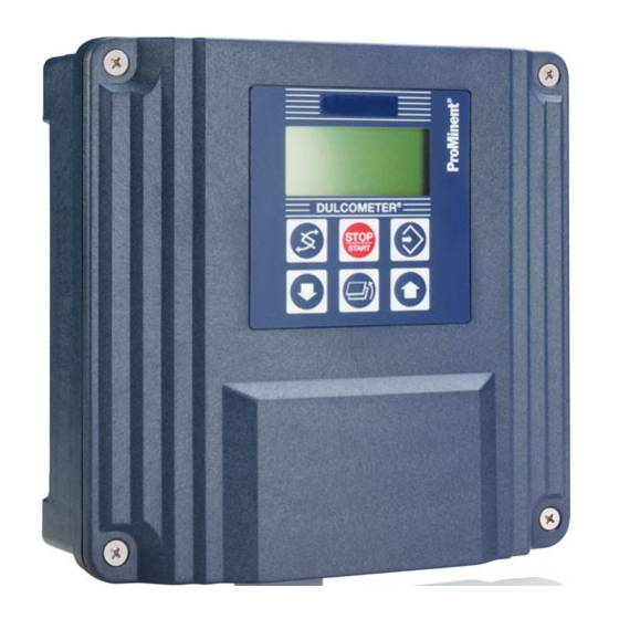
ProMinent DULCOMETER D1C Operating Instructions Manual
Part 3: adjustment and operation
measured variable h2o2 for perox sensor
Hide thumbs
Also See for DULCOMETER D1C:
- Operating instructions manual (33 pages) ,
- Operating instructions manual (28 pages) ,
- Operating instructions manual (28 pages)
Table of Contents
Advertisement
Operating Instructions
®
DULCOMETER
D1C
Part 3: Adjustment and Operation,
Measured Variable H
O
for PEROX Sensor
2
2
3312-4
Please first read the operating instructions completely! · Do not discard!
The operator shall be liable for any damage caused
by installation or operating errors!
Part No. 987936
ProMinent Dosiertechnik GmbH · D-69123 Heidelberg · Germany
BA DM 171 12/08 GB
Advertisement
Table of Contents

Related Manuals for ProMinent DULCOMETER D1C


Summary of Contents for ProMinent DULCOMETER D1C
- Page 1 Please first read the operating instructions completely! · Do not discard! The operator shall be liable for any damage caused by installation or operating errors! Part No. 987936 ProMinent Dosiertechnik GmbH · D-69123 Heidelberg · Germany BA DM 171 12/08 GB...
-
Page 2: Table Of Contents
General User Information Page General User Information ........................2 Measuring Principle ..........................3 Applications ..........................3 Operating Conditions .......................... 4 Set-Up of the Complete Measuring System ..................5 Set-Up Examples ........................5 Installation ............................6 Mechanical Installation ......................6 Installation in the Bypass Fitting ....................6 Electrical Installation ........................ -
Page 3: Measuring Principle
Measuring Principle Measuring Principle The PEROX measuring system is based on amperometric measurements with some special features not found in conventional systems. The small surface area measuring electrode is made of platinum (for hydrogen peroxide measurements) and is covered with a microporous diaphragm cap to make the readings largely independent of the liquid flow conditions. -
Page 4: Operating Conditions
Operating Conditions Operating Conditions Measuring ranges: 1 ... 20 mg/l 10 ... 200 mg/l 100 ... 2000 mg/l 2-electrode technology pH operating range: pH 2.5 ... 10 Temperature range: 0 ... 40 °C Temperature compensation: manually or automatically, depending on Identcode specification Permissible temperature change rate: <... -
Page 5: Set-Up Of The Complete Measuring System
Set-Up of the Complete Measuring System Set-Up Examples measuring system in wall-mounted set-up, with automatic temperature correction and flow rate monitoring: ® DULCOMETER D1C controller Measured variable PES/PAA Continuous flow measuring sensor with monitoring facility PT100; for long-distance signal transmission, temperature signal transmitter screwed onto the PT100 sensor type PEROX (4a) -
Page 6: Installation
Installation Mechanical Installation IMPORTANT • When installing the equipment, make quite sure that it is disconnected from the mains voltage! • Interpose a filter in the input feed line if the liquid to be measured is turbid or dirty! • Install a continuous flow sample cooler if the sample temperature is high or subject to large or rapid fluctuations! The PEROX sensor is delivered with a protecting cap to protect the diaphragm and the electrode surface. -
Page 7: Setting Of The Measuring Range
Installation Setting of the Measuring Range The measuring ranges 20/200/2,000 ppm are set via the DIP switch S1 at the transducer PEROX V1. The measuring range is factory-set to 0-200 ppm. The other measuring ranges can be set via the DIP switch positions listed in the table. Hydrogen peroxide (H Switch position S1 Measuring range [ppm]... -
Page 8: Commissioning
Commissioning SAFETY INSTRUCTIONS Disconnect the power supply voltage every time before mounting/removing sensors, signal transmitters and other components. The PEROX signal transmitter must not be disconnected from the PEROX sensor during operation. For the sequence of operating steps on the D1C-controller (settings, calibration, etc.), please consult the ®... -
Page 9: Calibration Intervals
Commissioning / 7 Operation Calibration Intervals The proper calibration intervals depend strongly on the process conditions and the substances actually present in the process water, therefore no generally valid specifications can be given. Under laboratory conditions (pure aqueous solutions of H ), the calibrations intervals are about 3 months. -
Page 10: Polishing The Electrode Surface
Operation Polishing the Electrode Surface - Put a pea-size amount of polishing paste onto a soft (paper) rag. - Press the electrode into the polishing paste and turn it under gentle pressure. - Completely remove the polishing paste from the electrode and sensor shaft by rinsing under lukewarm running water. -
Page 11: Spare Parts And Consumables
Spare Parts and Consumables sensor shaft, type H2.10 P, complete with diaphragm cap 792976 Transmitter, type PEROX V1 1034100 replacement diaphragm cap, type M 2.0P 792978 Temperature sensor, type PT 100 SE 305063 Temperature transmitter, type PT 100 V1 809128 Bypass fitting (3-fold) (hose connection 8x5) DGMA 320T000 Bypass fitting (3-fold) (screw fitting d16 / DN10) - Page 12 Operating Instructions DULCOMETER ® D1C, Part 3, Measured Variable H for PEROX Sensor Subject to modifications · Printed in Germany ProMinent Dosiertechnik GmbH · Im Schuhmachergewann 5-11 · D-69123 Heidelberg Telephone +49 6221 842-0 · Fax +49 6221 842-419 info@prominent.com · www.prominent.com...
Need help?
Do you have a question about the DULCOMETER D1C and is the answer not in the manual?
Questions and answers