ProMinent DULCOMETER D1C Operating Instructions Manual
Part 2: adjustment and operation
measured variable standard signal
Hide thumbs
Also See for DULCOMETER D1C:
- Operating instructions manual (33 pages) ,
- Operating instructions manual (25 pages) ,
- Operating instructions manual (12 pages)
Table of Contents
Advertisement
Quick Links
Operating Instructions
®
DULCOMETER
D1C
Part 2: Adjustment and Operation,
Measured Variable Standard Signal
D1C2-mA-001-GB
Type D
Type W
___ ___ ___ ___ ___ ___ ___ ___ ___ ___ ___ ___ ___
D1C A
Please enter the identity code of your device here!
Please completely read through operating instructions! · Do not discard!
The warranty shall be invalidated by damage caused by operating errors!
Part no. 987528
ProMinent Dosiertechnik GmbH · D-69123 Heidelberg · Germany
BA DM 147 04/07 GB
Advertisement
Table of Contents

Related Manuals for ProMinent DULCOMETER D1C


Summary of Contents for ProMinent DULCOMETER D1C
- Page 1 Please enter the identity code of your device here! Please completely read through operating instructions! · Do not discard! The warranty shall be invalidated by damage caused by operating errors! Part no. 987528 ProMinent Dosiertechnik GmbH · D-69123 Heidelberg · Germany BA DM 147 04/07 GB...
-
Page 2: Device Identification / Identity Code
Device Identification / Identity Code ® D1C A DULCOMETER Controller Series D1C / Version A Type of mounting Control panel installation 96 x 96 mm Wall mounting Operating voltage 230 V 50/60 Hz 115 V 50/60 Hz 200 V 50/60 Hz (only with panel installation) 100 V 50/60 Hz (only with panel installation) 24 V AC/DC Measured variable... -
Page 3: Table Of Contents
• Correct measuring and metering is only possible in the case of impeccable operation of the sensor. The sensor has to be calibrated / checked regularly! NOTE A form “Documentation of controller settings type D1C” is available under www.prominent.com/documentation_D1C for the purpose of documenting the controller settings. -
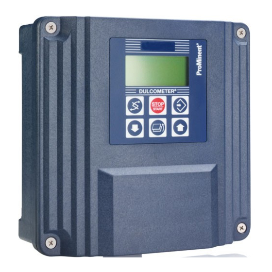
Page 4: Device Overview / Controls
Device Overview / Controls Display field Measured variable Standard signal (0/4–20 mA) Graphic display "Start/stop" button "Change" button "Enter" button "Branch back" button DULCOMETER ® "Up" "Down" STOP button button START D1C2-mA-002-GB CHANGE button UP button To change over within a menu level To increase a displayed numerical value and to change from one variable to and to change variables (flashing... -
Page 5: Functional Description
Functional Description NOTE Please refer to the description of the complete operating menu in Section 8 for a detailed description of the individual characteristics of the D1C controller! Operating Menu The DULCOMETER ® D1C controller permits settings to be made in two different menus – a “complete” and a “restricted”... -
Page 6: Display Symbols
Display Symbols The display of the DULCOMETER ® D1C controller uses the following symbols: Description Comment Symbol Limit value transgression Symbol Relay 1, upper left Symbol Relay 1, lower left Symbol Relay 2, upper right Symbol Relay 2, lower right Metering pump 1 Symbol Control off... -
Page 7: Operation Diagram
Operation diagram The various menus are selected with Permanent the CHANGE button display 1 The menu is started with the ENTER button Permanent BRANCH BACK to permanent display display 2 or to relevant setting menu Calibration Calibration menu notes Various Access code, correct Setting menus Parameter... -
Page 8: Restricted Operating Menu
Restricted Operating Menu / Layout The restricted operating menu permits simple operation of the most important parameters. The following overview shows the settings which can be selected: Permanent display 1 12.3 Permanent display 2 Positive values of setting variable: mea val. 12.3 % 70 % fd. -
Page 9: Description
Restricted Operating Menu / Description Permanent display 1 12.3 Permanent display 2 Positive values of setting variable: mea val. 12.3 % fd. fwd.: 70 % only with control Negative values of setting variable: 59 % reg. val.: (w = setpoint) 50 % D1C2-mA-011-GB Calibration of the standard signal (zero-point calibration) - Page 10 Restricted Operating Menu / Description Limit values Access to all setting menus can be blocked with an access code ! limit 2 upper limits 30.0 % setting ? limit 1 lower 26.0 % D1C2-mA-014-GB Possible values Initial value Increment Lower value Upper value Remarks Type of limit trans-...
- Page 11 Restricted Operating Menu / Description Possible values Initial value Increment Lower value Upper value Remarks Setpoint 50 % 0.1 % -5.0 % 105 % Measuring unit: % 10.00 mA 0.01 mA -1.00 mA 21 mA Measuring unit: mA 2 setpoints necessary for control with dead zone.
-
Page 12: Complete Operating Menu
Complete Operating Menu / Overview All parameters of the controller can be set in the complete operating menu (access see previous page). The following overview shows the settings which can be selected: Permanent display 1 12.3 Permanent display 2 12.3 % mea val. -
Page 13: Description
Complete Operating Menu / Description Permanent display 1 12.3 Permanent display 2 Positive values of setting variable: mea val. 12.3 % fd. fwd.: 70 % only with control Negative values of setting variable: 59 % reg. val.: (w = setpoint) 50 % D1C2-mA-018-GB Calibration of the standard signal (two-point calibration) - Page 14 Complete Operating Menu / Description Measuring variable Access to all setting menus can be blocked with an access code ! measuring unit measuring value setting ? measuring signal measuring unit: 0...100 % Permanent display 1 D1C2-mA-019-GB IMPORTANT The sensor must be recalibrated and the settings in all the menus checked after changing the assigned range! Possible values Initial value...
- Page 15 Complete Operating Menu / Description Measured value Access to all setting menus can be blocked with an access code ! Standard signal input mA measured value measured value measured value setting ? range adjustment range adjustment 4 mA 20 mA = 100.0 % 0.0 % measured value...
- Page 16 Complete Operating Menu / Description Relay for power control Access to all setting menus can be blocked with an access code ! Only with limit relay, solenoid valve relay or servomotor relays relay adjustment solenoid valve 1 solenoid valve 2 setting ? relay1: 10 s...
- Page 17 Complete Operating Menu / Description IMPORTANT The timer will reset in the event of a power failure. ® At the end of the (timer) cycle time the DULCOMETER D1C closes the assigned relay for the duration of “t on” (timer). “Pause” interrupts the timer. When the clock is shown in the LC display the timer can be reset to the start of the cycle at precisely this point using the enter button.
- Page 18 Complete Operating Menu / Description Limit values Access to all setting menus can be blocked with an access code ! limits fault limit 2 upper limits hyst.: 0.2 % setting? 30 % ∆t on: limit 1 lower control: 28 % relay 1: relay 2: - active closed...
- Page 19 Complete Operating Menu / Description Servomotor The operating range is defined by the total resistance range of the feedback potentiometer. The maximum limit of the range actually used is set by defining the control range. IMPORTANT • Activation of the servomotor must be carried out with the same meticulous care as taken when calibrating a measuring sensor.
- Page 20 Complete Operating Menu / Description Control Access to all setting menus can be blocked with an access code ! Note: The controlled variable is recalculated every second. Only suitable for processes with time constants greater than 30 s ! Only with control Positive values of setting variable: control control...
- Page 21 Complete Operating Menu / Description Feed forward control feed forward ctrl. feed forward ctrl. feed forward ctrl. feed forward ctrl. rated value disturb. variable setting ? Hz/mA 10.00 Hz additive 10 Hz feed forward ctrl. max. additive regulated value 100 % D1C2-mA-031-GB Possible values Initial value...
- Page 22 Complete Operating Menu / Description Standard signal output 2 Access to all setting menus can be blocked with an access code ! Control with standard signal control signal output 2 regulated value Only with 2 standard signal outputs regulated value: positive 0 mA = signal output 2...
- Page 23 Complete Operating Menu / Description Possible values Initial value Increment Lower value Upper value Remarks Alarm relay active active not active Pause normal normal hold Control input pause active closed active closed Reacts as a make contact active open Reacts as a break contact Alarm pause Alarm relay can be triggered by pause...
-
Page 24: Faults/Notes/Troubleshooting
©1996 ProMinent Dosiertechnik GmbH · D-69123 Heidelberg Operating Instructions DULCOMETER ® D1C, Part 2/Standard Signal Subject to modifications · Printed in the F.R.Germany ProMinent Dosiertechnik GmbH · Im Schuhmachergewann 5-11 · D-69123 Heidelberg Phone +49 6221 842-0 · Fax +49 6221 842-419 info@prominent.com · www.prominent.com...
Need help?
Do you have a question about the DULCOMETER D1C and is the answer not in the manual?
Questions and answers