Table of Contents
Advertisement
Advertisement
Table of Contents

Related Manuals for ProMinent DulcoFlow DFMa series


Summary of Contents for ProMinent DulcoFlow DFMa series
-
Page 1: Operating Instructions
Operating instructions Ultrasonic Flow Meter DulcoFlow DFMa ® Please carefully read these operating instructions before use! · Do not discard! The operator shall be liable for any damage caused by installation or operating errors! Technical changes reserved. Part no. 986007 BA MAZ 014 01/11 EN... - Page 2 ProMinent Dosiertechnik GmbH Im Schuhmachergewann 5-11 69123 Heidelberg Germany Telephone: +49 6221 842-0 Fax: +49 6221 842-617 email: info@prominent.com Internet: www.prominent.com) 986007, 1, en_GB © 2010...
- Page 3 Supplemental instructions Supplementary information Read the following supplementary information in its entirety! Should you already know this information, you have an even greater need of the Operating Instructions. The following are highlighted separately in the document: Enumerated lists Instructions Outcome of the instructions ð...
-
Page 4: Table Of Contents
Table of contents Table of contents Identity code..........................6 About this product........................8 Safety chapter......................... 9 Storage and transport......................12 Device overview........................13 Functional description......................14 Assembly and installation...................... 15 Installation........................15 Hydraulic Installation....................15 Electrical Installation..................... 17 Settings ..........................20 Operating unit....................... - Page 5 Table of contents Technical data........................50 Dimensions sheet........................53 EC Declaration of Conformity....................54 Decontamination declaration....................55 Index............................. 56...
-
Page 6: Identity Code
6/4 mm 8/5 mm 12/9 mm Electrical connection 2 m European 2 m Swiss 2 m Australian 2 m USA Signal output No output Current output Counter output Version With ProMinent Logo ® Without ProMinent Logo ® Accessories No accessories... - Page 7 Identity code...
-
Page 8: About This Product
About this product About this product The flow meter DulcoFlow is intended for use ® in measuring pulsing volume flows in the range from 0.1 to 80 l/h. All parts coming into contact with flow media are made from PVDF. This ensures that aggressive media can also be measured without problem. -
Page 9: Safety Chapter
The following signal words are used in these Observe the general limitations with regard operating instructions to identify different to viscosity limits, chemical resistance and severities of a hazard: density - see also ProMinent resistance list (In the product equipment catalogue or at www.prominent.com )! Signal Meaning Any other uses or modifications are pro‐... - Page 10 – Only fit parts to the device, which glasses, safety gloves, ...). Observe have been tested and recommended the safety data sheet for the feed by ProMinent. chemical. – Drain and flush the hydraulic parts before working on the device.
- Page 11 Technical personnel Customer Service department tion of hydraulic system Customer Service refers to service technicians, who have received proven training and have Electrical installation Electrician been authorised by ProMinent ® to work on the system. Operation Instructed personnel Maintenance Technical personnel...
-
Page 12: Storage And Transport
The "Decontamination Declaration Form" can be found in the Appendix or under www.prominent.com . Ambient conditions Data Value Unit Minimum storage and transport temperature -10 °C Maximum storage and transport temperature +50 °C... -
Page 13: Device Overview
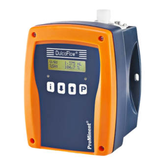
Device overview Device overview Fig. 1: Overview of equipment DulcoFlow with arrows showing flow ® Control elements - see chapter "Settings" - Feed chemical inlet "Operating unit" Feed chemical outlet Mains connection Signal output (option) -
Page 14: Functional Description
Functional description Functional description The DulcoFlow flow meter measures the ® volume flow of pulsing flows. The ultrasonic, time of flight measurement method is used. For the time of flight measurement, a sound signal is alternately transmitted in and against the direction of flow. -
Page 15: Assembly And Installation
Assembly and installation Assembly and installation Installation Safety information WARNING! Carry out the assembly work before the Install the device so that the hose between electrical installation is undertaken. it and the pump is approximately 30 cm long. This ensures it measures accurately. WARNING! Observe the information in the "Technical data"... - Page 16 Assembly and installation Installing the hosing: Cut off the ends of the hoses (6) so that Flow direction they are straight. The flow direction through the device goes Unscrew the union nut (5) and push from the bottom to the top. over the hose together with the clamp ring (4).
-
Page 17: Electrical Installation
Assembly and installation Electrical Installation WARNING! Danger of electric shock The use of a residual current circuit breaker drastically increases survival chances should persons come into contact with the mains voltage due to an electrical accident. – Always fit a residual current circuit breaker on-site. - Page 18 Assembly and installation Current output The following can be signalled via the current output (standard signal output (mA)): Instantaneous flow Fault Technical data: Data Value Unit Current* 0/4 .. 20 mA Maximum load 400 Ω * zero volt connection Counter output as stroke feedback output The counter output as stroke feedback output can be used to signal stroke feedback, pro‐...
- Page 19 Assembly and installation Counter output as frequency output The counter output as frequency output can be used to signal flow or an error, provided it is set accordingly - see chapter "Settings". Remove the connected socket. Remove the insulation of the leads to match the terminals of the other device. Crimp on a suitable cable end sleeve.
-
Page 20: Settings
Settings Settings Operating unit The stroke feedback LED (right) shows the fol‐ lowing information: Information DulcoFlow ® No pressure surge identified 1145.69 mL 502.13 mL/h green, illumi‐ Pressure surge detected - nated within tolerance red, illumi‐ Pressure surge detected - nated outside tolerance 8.1.3... - Page 21 Settings = set-up option main menu set-up set-up display cont. display Fig. 5: Navigation within the operating menu The control keys have different functions in the continuous display, in the operating menu and in the menu branches. In the continuous display Functions Changes to continuous dis‐...
- Page 22 Settings In a menu item of a menu branch Functions Switches between the continuous changing of a number and digit by digit changing Increase/change the set value Reduce/change the set value Accept the configured value and change to the next menu item of the menu branch.
-
Page 23: Checking Adjustable Variables
Settings Checking adjustable varia‐ Continuous displays for the "Mass" measured variable bles „mass“ was set under „Mode Before you adjust the flow meter, you can Measured variable“ .) è check the actual settings of the adjustable vari‐ ables: [ i ] ("i" for "Info"), if the Press the key Continuous display Description... -
Page 24: Operating Menu Overview
Settings Operating menu overview cont. display set to zero quantity and strokes acknowledge error main menu menu mode measurand measurand main menu menu set-up set-up display display menu * Dependent on identity code counter outp.* counter outp.* menu current output* current output* menu service... -
Page 25: Changing To Adjustment Mode
Settings main menu info info main menu language language Fig. 7 Changing to adjustment 8.4.2 "Set-up" main menu mode main menu set-up [P] key is pressed for 2 seconds in a con‐ If the tinuous display, the device changes to adjust‐ The following menus can be selected from the ment mode. - Page 26 Settings 8.4.2.1 "Display" menu set-up quantity unit flow unit damping flow display mL/h 30.00 s B0228 „display“ menu, the units can be selected for the quantities and flow. In the Moreover, the damping of the displayed flow values can be changed (not for quantities), if they change too quickly / slowly in the display.
- Page 27 It works like a relay in status NO. stroke feedback For stroke feedback, e.g. to a Prominent metering pump, as with a Flow Control ® dosing monitor, the cable must be fed from the counter output to the "dosing monitor"...
- Page 28 Settings 8.4.2.3 "Current output" menu (identity code characteristic "signal output" "1") set-up current output current range flow unit current output signal current 4...20 mA mL/h 0/4 mA value 20 mA value 0.68 mL/h 897.65 mL/h current output error current error current bubbles B0234 „current output“...
-
Page 29: Calibration" Main Menu
Settings 8.4.2.4 "service" menu set-up service code service 0000 B0229 The "service" menu is password protected and only for customer service. 8.4.3 "Calibration" main menu main menu calibration From the "calibration" menu either the flow measurement can be calibrated or the stroke feedback set up. - Page 30 Settings About setpoint and tolerances calibration stroke feedback volume (stroke) volume (stroke) stroke feedback set-point 0.347 mL 0.347 mL tolerance lower tolerance upper tolerance tolerance (%) -010.00 % +020.00 % B0230 Specify the allowed range for the lifting volume V/H via the setpoint of the lifting volume V/H and tolerances in %: „calibration è...
- Page 31 Settings Upper limit values calibration stroke feedback volume (stroke) volume (stroke) stroke feedback set-point 0.347 mL 0.347 mL tolerance tolerance (%) tolerance lower limit upper limit limits 0.312 mL 0.416 mL B0231 Alternatively, the desired limits for the allowed range of the lifting volume can be entered under „lower limit“...
- Page 32 Settings The desired setpoint can also be entered, without having to use the stroke adjustment dial or the pump having to be running, directly under „volume (stroke)“ using the [arrow keys] . 8.4.3.1.2 For "mass" The permitted range for the mass per stroke m/ H can be specified in this menu.
- Page 33 Settings About setpoint and tolerances calibration stroke feedback mass (stroke) mass (stroke) stroke feedback set-point 0.347 g 0.347 g tolerance lower tolerance upper tolerance tolerance (%) -010.00 % +020.00 % B0232 Specify the allowed range for the mass per stroke m/H via the setpoint of the lifting volume m/H and tolerances in %: „calibration è...
- Page 34 Settings Upper limit values calibration stroke feedback mass (stroke) mass (stroke) stroke feedback set-point 0.347 g 0.347 g tolerance tolerance (%) tolerance lower limit upper limit limits 0.312 g 0.416 g B0233 „lower Alternatively, the desired limits for the allowed range of the stroke mass can be entered under limit“...
- Page 35 Settings The desired setpoint can also be entered, without having to use the stroke adjustment dial or the pump having to be running, directly under „mass (stroke)“ using the [arrow keys] . 8.4.3.2 Calibrate "quantity" Only calibrate the quantity flow if the dis‐ played values do not attain the expected accuracy.
- Page 36 Settings 8.4.3.2.1 By corr. factor calibration stroke feedback calibration quantity corr. factor quantity corr. factor 101.23 % B0244 If the new correction factor is know in %, it can be entered directly here. It is obtained by dividing a value you have measured yourself by the displayed value and multiplying the result by 100.
- Page 37 Settings Volume calibration stroke feedback calibration quantity quantity corr. factor quantity actual volume nominal volume meas. Value 54.72 mL 52.13 mL corr. factor 95.27 % B0226...
- Page 38 Settings Requirements: 1 measuring cylinder which can be read sufficiently accurately The metering pump suction line is fed, bubble-free into the measuring cylinder. Record the fluid level in the measuring cylinder. „calibration stroke feedback“ using the [arrow keys] to the menu Change from the menu item „calibration quantity“...
- Page 39 Settings Mass calibration stroke feedback calibration quantity quantity corr. factor quantity actual mass nominal mass meas. Value 54.72 g 52.13 g corr. factor 95.27 % B0227...
-
Page 40: Zero Set" Main Menu
Settings Requirements: 1 weighing instrument which can be read sufficiently accurately 1 vessel with feed chemical the suction line is fed, bubble-free into the measuring vessel. Zero the weighing instrument. „calibration stroke feedback“ using the [arrow keys] to the menu Change from the menu item „calibration quantity“... -
Page 41: Info" Main Menu
Settings 8.4.5 "Info" main menu main menu info This information can be read-off in the "info" main menu: Code Meaning Identity code Serial number Hardware version Software version Bootloader 8.4.6 "Language" main menu main menu language The operating language can be selected from the "language"... -
Page 42: Start Up
Start up Start up Connect the device hydraulically to the installation. Connect the device to the supply voltage. Use with the metering pump delta is only ® possible if the pump is set to "dosing" - If necessary set: "set-up" (discharge stroke)" - "fast". Ä... - Page 43 Start up (for identity code characteristic "signal output" "2") „set-up è counter output Under puls/freq. è error output“ set the è desired error result. Cause the error to occur and check whether everything functions as desired.
-
Page 44: Maintenance, Repair And Disposal
Maintenance, repair and disposal Maintenance, repair and disposal WARNING! Danger from chemical residues There is normally chemical residue in the measurement pipe and housing after ope‐ ration. This chemical residue could be haz‐ ardous to people. – It is mandatory that the safety infor‐ mation relating to the "Storage, trans‐... -
Page 45: Maintenance
If this is not the case, check for the cause and rectify as necessary. Check whether feed chemical is coming out. If necessary, carefully wipe the device with a soft cloth and soapy water. 10.2 Repairs Only ProMinent of customer service authorised by ProMinent may repair the DulcoFlow flow ®... -
Page 46: Troubleshooting
Troubleshooting Troubleshooting WARNING! Warning of dangerous or unknown feed chemical Should a dangerous or unknown feed chemical be used: It may escape from the hydraulic components during maintenance work. – Before maintenance work, take appropriate protective measures (safety glasses, safety gloves, ...). Observe the safety data sheet for the feed chemical. -
Page 47: Dulcoflow ® Error
Troubleshooting 11.1 DulcoFlow error ® Faults with error messages The left device LED lights up red if an error exists. Fault description Cause Remedy Bubbles detected There are too many bubbles or particles Avoid bubbles or particles in the in the feed chemical. feed chemical. -
Page 48: Pump Error
Troubleshooting 11.2 Pump error To return the pump to operating status after one of the following errors, press the key [P] . In the event of an error an LED lights up red and the flow identifier flashes. Fault description Cause Remedy The pump stops... -
Page 49: All Other Faults
The stroke adjustment dial - see metering pump operating instructions is mis-set The feed chemical is too - see metering pump operating instructions viscous 11.3 All Other Faults All other faults: Inform your customer service department or your ProMinent branch. -
Page 50: Technical Data
Technical data Technical data Performance data Data Value Unit Measuring range, pulsing, type 05: 0.1... 13 L/h Measuring range, pulsing, type 08: 0.6... 80 L/h Smallest measurable lifting volume, pulsing approx. 0.03 mL/stroke Accuracy over at least 100 strokes: ± 2 %* * relative to the measured value Electrical data Data... - Page 51 Technical data Ambient conditions Data Value Unit Minimum storage and transport temperature -10 °C Maximum storage and transport temperature +50 °C Ambient temperature in operation, min. -10 °C Ambient temperature in operation, max. +50 °C Maximum air humidity * 95 % rel. humidity * non-condensing Material Component...
- Page 52 Technical data Compatibility Type Pumps Beta, gala: 1000 - 0413/0713 delta: 1608 - 1612 Beta, gala: 0220/0420 - 0232 delta: 1020 - 0280...
-
Page 53: Dimensions Sheet
Dimensions sheet Dimensions sheet 121.6 35.5 M20x1,5 Fig. 8: Dimensional drawing DulcoFlow - dimensions sheet in mm ®... -
Page 54: Ec Declaration Of Conformity
EC Declaration of Conformity - Original - EC Declaration of Conformity ProMinent Dosiertechnik GmbH Im Schuhmachergewann 5 - 11 DE - 69123 Heidelberg hereby declare that, the product specified in the following complies with the relevant basic health and safety rules of the EC Directive, on the basis of its functional concept and design and in the version marketed by us. -
Page 55: Decontamination Declaration
Decontamination declaration Decontamination declaration... -
Page 56: Index
Index Index About this product.......... 8 HW............... 41 Hydraulic system.......... 17 BL..............41 bubbles............28 ID..............41 Identity code........... 6 Calibration............ 29 Info............... 41 Checking............23 Information in the event of an emergency..10 Checking adjustable variables..... 23 Installation............ 15 Control keys.......... - Page 57 Index SN..............41 Transport............12 Standard signal output (mA)......18 Troubleshooting........... 46 Start up............42 Storage............12 Units............. 26 stroke feedback........27, 29 Stroke feedback........... 18 Volume........25, 29, 35, 37 Supplementary information......3 Volume flow..........25 SW............... 41 Warning sign..........9 Technical data..........
Need help?
Do you have a question about the DulcoFlow DFMa series and is the answer not in the manual?
Questions and answers