Omron CJ1W-ECT21 Operation Manual
Machine automation controller, cj / nj-series, ethercat slave unit, cpu unit
Hide thumbs
Also See for CJ1W-ECT21:
- Quick start manual (14 pages) ,
- Operation manual (154 pages) ,
- Operation manual (317 pages)

Related Manuals for Omron CJ1W-ECT21


Summary of Contents for Omron CJ1W-ECT21
- Page 1 Machine Automation Controller CJ-series EtherCAT Slave Unit ® Operation Manual for NJ-series CPU Unit CJ1W-ECT21 EtherCAT Slave Unit W542-E1-01...
- Page 2 No patent liability is assumed with respect to the use of the information contained herein. Moreover, because OMRON is constantly striving to improve its high-quality products, the information contained in this manual is subject to change without notice. Every precaution has been taken in the preparation of this manual. Neverthe- less, OMRON assumes no responsibility for errors or omissions.
-
Page 3: Introduction
Thank you for purchasing a CJ-series CJ1W-ECT21 EtherCAT Slave Unit. This manual contains information that is necessary to use the CJ-series CJ1W-ECT21 EtherCAT Slave Unit for an NJ-series CPU Unit. Please read this manual and make sure you understand the functional- ity and performance of the NJ-series CPU Unit before you attempt to use it in a control system. -
Page 4: Table Of Contents
CONTENTS CONTENTS Introduction ......................1 Intended Audience............................1 Applicable Products ............................. 1 CONTENTS........................ 2 Manual Structure ...................... 7 Page Structure and Icons ..........................7 Special Information ............................8 Precaution on Terminology .......................... 8 Terms and Conditions Agreement ................9 Warranty, Limitations of Liability ........................9 Application Considerations ........................ -
Page 5: Contents
CONTENTS 1-4-2 Functional and Performance Specifications ................1-9 1-4-3 Dimensions ..........................1-10 Setting Procedures......................1-11 Section 2 Nomenclature and Installation Nomenclature......................... 2-2 2-1-1 Nomenclature and Functions...................... 2-2 2-1-2 Indicators ............................ 2-2 2-1-3 Switch Settings ........................... 2-5 Installing the EtherCAT Slave Unit..................2-7 2-2-1 System Configuration Precautions ..................... - Page 6 System Configuration........................A-2 A-1-2 Setting Condition.........................A-3 A-1-3 Flow of the Setting Procedure.....................A-4 A-1-4 CJ1W-ECT21 Setting Procedure ....................A-4 A-1-5 EtherCAT Master Setting Procedure...................A-8 A-1-6 Start EtherCAT Communication ....................A-10 A-2 Programming Example to Detect Valid I/O Process Data ..........A-11 A-3 Process Data Exchange in PROGRAM Mode..............A-12 A-3-1 Detection Method and Timing Considerations ................A-12...
- Page 7 CONTENTS A-5-5 PDO Mapping Objects ......................A-25 A-5-6 Sync Manager Communication Objects ................... A-28 A-5-7 Device Profile Area ........................A-31 A-6 Version Information......................A-33 Index CJ-series EtherCAT Slave Units Operation Manual for NJ-series CPU Unit (W542)
- Page 8 CONTENTS CJ-series EtherCAT Slave Units Operation Manual for NJ-series CPU Unit (W542)
-
Page 9: Manual Structure
Manual Structure Manual Structure Page Structure and Icons The following page structure is used in this manual. Level 1 heading 4 Installation and Wiring Level 2 heading Level 3 heading Mounting Units Level 2 heading Gives the current Level 3 heading headings. -
Page 10: Special Information
Manual Structure Special Information Special information in this manual is classified as follows: Precautions for Safe Use Precautions on what to do and what not to do to ensure safe usage of the product. Precautions for Correct Use Precautions on what to do and what not to do to ensure proper operation and performance. Additional Information Additional information to read as required. -
Page 11: Terms And Conditions Agreement
Omron’s exclusive warranty is that the Products will be free from defects in materials and workman- ship for a period of twelve months from the date of sale by Omron (or such other period expressed in writing by Omron). Omron disclaims all other warranties, express or implied. -
Page 12: Application Considerations
Disclaimers Performance Data Data presented in Omron Company websites, catalogs and other materials is provided as a guide for the user in determining suitability and does not constitute a warranty. It may represent the result of Omron’s test conditions, and the user must correlate it to actual application requirements. Actual perfor- mance is subject to the Omron’s Warranty and Limitations of Liability. -
Page 13: Safety Precautions
Safety Precautions Safety Precautions Definition of Precautionary Information The following notation is used in this manual to provide precautions required to ensure safe usage of an EtherCAT Slave Unit. The safety precautions that are provided are extremely important to safety. Always read and heed the information provided in all safety precautions. -
Page 14: Warnings
Safety Precautions Warnings WARNING During Power Supply Do not touch any of the terminals or terminal blocks while the power is being supplied. Doing so may result in electric shock. Do not attempt to take any Unit apart. In particular, high-voltage parts are present in the Power Supply Unit while power is supplied or immediately after power is turned OFF. - Page 15 Safety Precautions The CPU Unit refreshes I/O even when the program is stopped (i.e., even in PROGRAM mode). Confirm safety thoroughly in advance before changing the status of any part of memory allocated to I/O Units, Special I/O Units, or CPU Bus Units.
-
Page 16: Cautions
Safety Precautions Cautions Caution Application Do not touch any Unit when power is being supplied or immediately after the power supply is turned OFF. Doing so may result in burn injury. Wiring Be sure that all terminal screws and cable connector screws are tightened to the torque specified in the relevant manuals. -
Page 17: Precautions For Safe Use
Precautions for Safe Use Precautions for Safe Use Online Editing When performing online editing with the combination of a CPU Unit with a unit version of 1.04 or later and Sysmac Studio version 1.05 or higher, the CPU Unit saves a program updated by the online editing to built-in non-volatile memory. - Page 18 Precautions for Safe Use Power Supply Design • Do not exceed the rated supply capacity of the Power Supply Units in the NJ-series Controller. The rated supply capacities are given in the NJ-series CPU Unit Hardware User’s Manual (Cat. No. W500).
- Page 19 Precautions for Safe Use Turning OFF the Power Supply • Never turn OFF the power supply to the Controller when the BUSY indicator is flashing. While the BUSY indicator is lit, the user program and settings in the CPU Unit are being backed up in the built-in non-volatile memory.
- Page 20 Precautions for Safe Use Battery Backup • The user program and initial values for the variables are stored in non-volatile memory in the CPU Unit. The present values of variables with the Retain attribute and the values of the Holding, DM, and EM Areas in the memory used for CJ-series Units are backed up by a Battery.
- Page 21 Precautions for Safe Use Unit Replacement • Make sure that the required data, including the user program, configurations, settings, variables, and memory used for CJ-series Units is transferred to a CPU Unit that was replaced and to externally connected devices before restarting operation. Be sure to include the tag data link settings, routing tables, and other CPU Bus Unit data, which are stored in the CPU Unit.
-
Page 22: Precautions For Correct Use
Precautions for Correct Use Precautions for Correct Use Storage, Mounting, and Wiring • Do not operate or store the Controller in the following locations. Operation may stop or malfunctions may occur. a) Locations subject to direct sunlight b) Locations subject to temperatures or humidity outside the range specified in the specifications c) Locations subject to condensation as the result of severe changes in temperature d) Locations subject to corrosive or flammable gases e) Locations subject to dust (especially iron dust) or salts... - Page 23 Precautions for Correct Use SD Memory Cards • Insert the SD Memory Card all the way. CJ-series EtherCAT Slave Units Operation Manual for NJ-series CPU Unit (W542)
-
Page 24: Regulations And Standards
Concepts EMC Directive OMRON devices that comply with EC Directives also conform to the related EMC standards so that they can be more easily built into other devices or the overall machine. The actual products have been checked for conformity to EMC standards.*1 Whether the products conform to the standards in the system used by the customer, however, must be checked by the customer. -
Page 25: Conformance To Shipbuilding Standards
TAH-06-683 Conformance to KC Standards Observe the following precaution if you use the CJ1W-ECT21 EtherCAT Slave Units in Korea. Class A Device (Broadcasting Communications Device for Office Use) This device obtained EMC registration for office use (Class A), and it is intended to be used in places other than homes. -
Page 26: Unit Versions
Lot number and Gives the lot number and serial number of the Unit. serial number • YYMMDD: Lot number ( : For use by OMRON) • xxxx: Serial number Confirming Unit Versions with Sysmac Studio You can use the Production Information on the Sysmac Studio to check the unit version of the CPU Unit, CJ-series Special I/O Units and CJ-series CPU Bus Units. -
Page 27: Unit Versions And Sysmac Studio Versions
Unit Versions Right-click any open space in the Unit Editor and select Production Information. The Production Information Dialog Box is displayed. Simple Display Detailed Display In this example, “Ver.1.00” is displayed next to the unit model. The following items are displayed. CPU Unit CJ-series Units Unit model... -
Page 28: Related Manuals
The following manuals are related. Use these manuals for reference. Manual name Cat. No. Model numbers Application Description W542 CJ1W-ECT21 Learning about the func- The functions and operating procedures when CJ-series EtherCAT® tions and operating proce- the CJ-series EtherCAT Slave Unit is used in an Slave Units Operation dures when the CJ-series NJ-series system configuration are described. -
Page 29: Terminology
Terminology Terminology Term Abbreviation Description application layer status, AL status Status for indicating information on errors that occur in an application on a slave. CAN application protocol over Ether- A CAN application protocol service implemented on EtherCAT. CAN in Automation CiA is the international users' and manufacturers' group that develops and supports higher-layer proto- cols. - Page 30 Terminology Term Abbreviation Description process data object A structure that describes the mappings of parameters that have one or more process data entities. receive PDO RxPDO A process data object received by an EtherCAT slave. Safe-Operational A state in EtherCAT communications where only SDO communications and reading input data from slaves are possible.
-
Page 31: Revision History
Revision History Revision History A manual revision code appears as a suffix to the catalog number on the front and back covers of the manual. W542-E1-01 Cat. No. Revision code Revision code Date Revised content April 2015 Original production CJ-series EtherCAT Slave Units Operation Manual for NJ-series CPU Unit (W542) - Page 32 Revision History CJ-series EtherCAT Slave Units Operation Manual for NJ-series CPU Unit (W542)
-
Page 33: Sections In This Manual
Sections in this Manual Sections in this Manual Features and System Configuration Nomenclature and Installation Data Exchange with the CPU Unit EtherCAT Communications Troubleshooting Maintenance and Replacement Appendices Index CJ-series EtherCAT Slave Units Operation Manual for NJ-series CPU Unit (W542) - Page 34 Sections in this Manual CJ-series EtherCAT Slave Units Operation Manual for NJ-series CPU Unit (W542)
-
Page 35: Features And System Configuration
Features and System Configura- tion This section provides an introduction to EtherCAT networks and includes features, sys- tem configurations, specifications and setting procedures. 1-1 Introduction to EtherCAT ........1-2 1-1-1 How EtherCAT Works . -
Page 36: Introduction To Ethercat
1 Features and System Configuration Introduction to EtherCAT EtherCAT (Ethernet Control Automation Technology) is a high-performance industrial network system that enables faster and more efficient communications based on Ethernet. Each node achieves a short communications cycle time by transmitting Ethernet frames at high speed. Although EtherCAT is a unique communications protocol, standard Ethernet technology is used for the physical layer, which means you can use Ethernet cables for wider application. -
Page 37: Types Of Ethercat Communications
1 Features and System Configuration Ethernet frame Ethernet Ethernet data (1,498 bytes max.) header 1st to nth EtherCAT datagrams EtherCAT frame EtherCAT header 1st EtherCAT 2nd EtherCAT ..nth EtherCAT datagram datagram datagram Header Data WKC: Working counter 1-1-2 Types of EtherCAT Communications The following 2 types of communications are available with EtherCAT. - Page 38 1 Features and System Configuration EtherCAT master Slave Slave Slave Slave Ethernet frame Ether Ethernet 1st EtherCAT 2nd EtherCAT 3rd EtherCAT header datagram datagram datagram header Logical process data Data a Data b Data c Mailbox Communications (SDO Communications) SDO communications is used to perform message communications. Whenever necessary, the EtherCAT master sends a command to a slave, and then the slave returns a response to the EtherCAT master.
-
Page 39: Ethercat Slave Unit Features
1 Features and System Configuration EtherCAT Slave Unit Features The EtherCAT Slave Unit has the following features when used with the NJ-series CPU Unit. Data Exchange Between EtherCAT Master and CPU Unit Exchange data over the EtherCAT network between the EtherCAT master and the CPU Unit through the EtherCAT Slave Unit. - Page 40 1 Features and System Configuration Integration with Other Networks Interface with multiple networks such as EtherCAT and DeviceNet. EtherCAT master EtherCAT network EtherCAT network CPU Unit EtherCAT Slave Unit DeviceNet Master Unit DeviceNet network DeviceNet slaves 1 - 6 CJ-series EtherCAT Slave Units Operation Manual for NJ-series CPU Unit (W542)
-
Page 41: System Configuration Of Cj-Series Ethercat Slave Unit
.xml (F) ESI files Built-in EtherCAT port (D) Sysmac Studio Support Software (E) Communications cable (B) CJ-series Ethernet cables EtherCAT Slave Unit CJ1W-ECT21 Input port Output port (C) NJ-series CPU Unit Letter Item Description EtherCAT master The EtherCAT master manages the EtherCAT network, monitors the status of the slaves and exchanges I/O data with the slaves. -
Page 42: A-6 Version Information
File) ware to easily allocate slave process data and make other settings. The ESI files for OMRON EtherCAT slaves are already installed in the Sys- mac Studio. You can update the Sysmac Studio to get the ESI files for the most recent models. -
Page 43: Specifications
The general specifications conform to those of the NJ-series CPU Units. 1-4-2 Functional and Performance Specifications This section provides the functional and performance specifications of the EtherCAT Slave Unit. Item Specification Model number CJ1W-ECT21 Applicable Controller NJ Series Unit classification CPU Bus Unit Applicable unit numbers 0 to F... -
Page 44: Dimensions
1 Features and System Configuration Item Specification Weight 97 g max. 31 × 90 × 65 mm (W × H × D) Dimensions *1. Access via the device variables for CJ-series Unit. *2. Using the user-defined variable for R/W to the allocation area. *3. -
Page 45: Setting Procedures
1 Features and System Configuration Setting Procedures The basic setting procedures for the EtherCAT Slave Unit are described below. Use the Sysmac Studio to create programs and configure the EtherCAT Slave Unit. Procedure Item Description Reference Creating a proj- Create a project in the Sysmac Studio. Sysmac Studio Ver- sion 1 Operation Man- ual (Cat. - Page 46 1 Features and System Configuration Procedure Item Description Reference Turning ON Turn ON the power supply to the Sysmac Studio Ver- power to the NJ-series Controller. sion 1 Operation Man- NJ-series Con- ual (Cat. No. W504) troller Online connec- Use the Sysmac Studio to establish com- tion from Sys- munications with the NJ-series Controller mac Studio...
- Page 47 1 Features and System Configuration Procedure Item Description Reference Checking indica- Check the indicators on the EtherCAT • 2-1-2 Indicators on tors master and the EtherCAT Slave Unit. page 2-2 • 5-2-1 Checking for Errors and Trouble- shooting with the Indicators on page Confirming Operation •...
- Page 48 1 Features and System Configuration 1 - 14 CJ-series EtherCAT Slave Units Operation Manual for NJ-series CPU Unit (W542)
-
Page 49: Nomenclature And Installation
Nomenclature and Installation This section describes the nomenclature, installation and wiring of the EtherCAT Slave Unit. 2-1 Nomenclature ..........2-2 2-1-1 Nomenclature and Functions . -
Page 50: Nomenclature
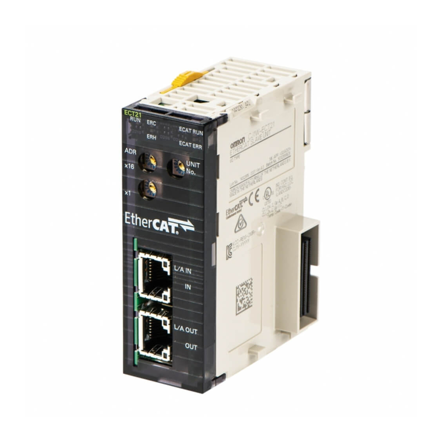
2 Nomenclature and Installation Nomenclature This section provides nomenclature for the EtherCAT Slave Unit. 2-1-1 Nomenclature and Functions This section provides the names and functions of the items on the front panel of the EtherCAT Slave Unit. Letter Name Function Indicators The indicators show the current operating status of the Unit and the connection status of the IN and OUT EtherCAT ports. - Page 51 2 Nomenclature and Installation Overview of Indicators Name Meaning L/A IN The L/A IN indicator shows the link activity of the input port. L/A OUT The L/A OUT indicator shows the link activity of the output port. ECAT RUN The ECAT RUN indicator shows the operating status of EtherCAT communications for the EtherCAT Slave Unit.
- Page 52 2 Nomenclature and Installation Name Color Status Meaning ECAT ERR • Special Unit Error • ESC Initial Error Blinking • CPU Unit Major Fault • CPU Unit Watchdog Timer Error • CPU Unit Service Monitoring Error • I/O Refresh Error •...
-
Page 53: Switch Settings
2 Nomenclature and Installation Indicator State Timing The flashing patterns for flickering, blinking, single flash, and double flash are given below. 50 ms Flickering Blinking 200 ms 200 ms 1,000 ms Single flash 1,000 ms Double flash 200 ms 200 ms 200 ms 2-1-3 Switch Settings... - Page 54 The value of node address is loaded to register 0012h of the EtherCAT slave controller when the power supply to the CJ1W-ECT21 is turned ON. The upper switch sets the sixteens digit (most significant digit) and the lower switch sets the ones digit (least significant digit).
-
Page 55: Installing The Ethercat Slave Unit
2 Nomenclature and Installation Installing the EtherCAT Slave Unit This section describes how to mount the EtherCAT Slave Unit to an NJ-series system. 2-2-1 System Configuration Precautions You can mount up to 16 Units on the CPU Rack or an Expansion Rack per CPU Unit (but no more than 10 Units on one Rack). -
Page 56: Handling Precautions
2 Nomenclature and Installation 2-2-3 Handling Precautions This section provides handling precautions for the EtherCAT Slave Unit. • Always turn OFF the Controller before you mount or dismount a Unit or connect or disconnect cables. • Provide separate conduits or ducts for the I/O lines to prevent noise from high-tension lines or power lines. -
Page 57: Ethercat Network Wiring
2 Nomenclature and Installation EtherCAT Network Wiring This section describes how to install the EtherCAT network. 2-3-1 Installation Standards To ensure that the EtherCAT communication network is installed properly, refer to IEC 61784-5-12 stan- dard in conjunction with IEC 61918. 2-3-2 Installation Precautions Basic precautions for the installation of EtherCAT networks are provided below. - Page 58 Recommended products are given in the following tables. Cables with Connectors Sizes and Conductor Pairs: AWG 22 × 2 Pairs Product name Manufacturer Model Length (m) Cables with Connec- OMRON Corporation XS5W-T421-AMD-K tors on Both Ends XS5W-T421-BMD-K (RJ45/RJ45) XS5W-T421-CMD-K XS5W-T421-DMD-K XS5W-T421-GMD-K...
-
Page 59: Pin Arrangements Of Communications Connectors
Nihon Electric Wire & Cable PNET/B Co., Ltd. RJ45 Assembly Connectors OMRON Corporation XS6G-T421-1 *1. A combination of the above cables and connectors is recommended for use. Precautions for Correct Use • The maximum length between nodes is 100 m. However, some cables are specified for less than 100 m. -
Page 60: Connecting Communications Cables And Connectors
2 Nomenclature and Installation 2-3-5 Connecting Communications Cables and Connectors Use straight connections for the communications cables and connectors, as shown below. Wire color Wire color Pin No. Pin No. White-Green White-Green Green Green White-Orange White-Orange Blue Blue White-Blue White-Blue Orange Orange White-Brown... - Page 61 2 Nomenclature and Installation EtherCAT master Communications cable Input port Output port EtherCAT slaves EtherCAT Slave Unit Do not connect anything. Last EtherCAT slave Precautions for Correct Use • The cable between any two nodes (L1, L2 ... Ln) must be 100 m or less. •...
- Page 62 2 Nomenclature and Installation 2 - 14 CJ-series EtherCAT Slave Units Operation Manual for NJ-series CPU Unit (W542)
-
Page 63: Data Exchange With The Cpu Unit
Data Exchange with the CPU Unit This section describes the words allocated to the EtherCAT Slave Unit. These words both enable controlling the EtherCAT Slave Unit and accessing Unit and Slave status. 3-1 Data Exchange Between the EtherCAT Slave Unit and the CPU Unit ..3-2 3-1-1 Data Flow . -
Page 64: Data Exchange Between The Ethercat Slave Unit And The Cpu Unit
3 Data Exchange with the CPU Unit Data Exchange Between the Ether- CAT Slave Unit and the CPU Unit Data exchange between this Unit and the CPU Units uses the I/O port and memory for CJ-series Unit allocated to the EtherCAT Slave Unit. 3-1-1 Data Flow The CPU Units and CJ-series EtherCAT Slave Units exchange data as shown in the table and chart... - Page 65 3 Data Exchange with the CPU Unit CPU Unit EtherCAT Slave Unit I/O port User program Unit Status, Unit Status, Slave Status Slave Status Device variable AT specification for CJ-series Unit Unit/Slave status (I/O refresh) I/O Communication I/O Communication Area Setting and Area Setting and I/O Communication Area Reference Tables...
-
Page 66: Accessing From The User Program
3 Data Exchange with the CPU Unit The EtherCAT Slave Unit has two types of I/O ports; one is for the following unit status/slave status data and the other is for I/O communication area setting and reference tables. Unit Status, Slave Status Unit operating status and error data are allocated with these I/O ports. - Page 67 3 Data Exchange with the CPU Unit How to Create Device Variables for CJ-series Unit Use I/O Map in Sysmac Studio to allocate device variables for CJ-series Unit to an I/O port. Specify variable names using one of the methods shown below. (a) Select and allocate existing variables.
- Page 68 3 Data Exchange with the CPU Unit In this case, the I/O data of each area is allocated as follows: Words I/O data allocated CIO 3200 Output001 CIO 3299 Output100 CIO 3300 Input001 CIO 3399 Input100 Allocate the I/O data to the user-defined variables as shown in the examples below. The example below uses the following data types: •...
- Page 69 3 Data Exchange with the CPU Unit The example below uses the following data types: • Slave_OutData_C (union) • Slave_InData_C (union) When you use the union, prepare the union data type Mem that you can access with WORD and BOOL as shown below.
- Page 70 3 Data Exchange with the CPU Unit I/O data User-defined variable name Address Input001, Bit 1 Slave_InData_B[0,1] 3300.01 Input100, Bit 15 Slave_InData_B[99,15] 3399.15 The user program accesses the I/O data with BOOL-type variables. When the user program accesses the I/O data with both WORD type and BOOL type, use the union-type user-defined variables Slave_OutData_C and Slave_InData_C defined in the example.
-
Page 71: Device Variables For Cj-Series Unit (Status)
3 Data Exchange with the CPU Unit Device Variables for CJ-series Unit (Status) This section describes the device variables Unit Status and Slave Status for the CJ-series Unit. In this section, the variable names that are created automatically in the I/O Map are used. 3-2-1 List of Device Variables for CJ-series Unit When you operate and reference Unit status and slave status, use the following device variables for... - Page 72 3 Data Exchange with the CPU Unit The following device variables for CJ-series Unit are used to reference individual information. Name of device variables Type Name Function for CJ-series Unit *_UnitErr BOOL Unit TRUE: Error Displays EtherCAT Slave Unit operating errors. *_UnitErr (Unit Error) changes to TRUE if any bit from 01 to 15 in *_Unit1Sta (Unit Status 1) is TRUE (OR information of bits 01 to 15).
-
Page 73: Unit Status 2
3 Data Exchange with the CPU Unit 3-2-3 Unit Status 2 The following device variable for CJ-series Unit is used to reference all information of Unit Status 2. Name of device variable for Type Name Function CJ-series Unit *_Unit2Sta WORD Unit Status 2 Bit 00: Online Status Bit 01: Reserved by system... -
Page 74: Slave Status 1
3 Data Exchange with the CPU Unit 3-2-4 Slave Status 1 The following device variable for CJ-series Unit is used to reference all information of Slave Status 1. Name of device variable Type Name Function for CJ-series Unit *_Slave1Sta WORD Slave Status 1 Bit 00: Reserved by system Bit 01: Slave AL Status Error... - Page 75 3 Data Exchange with the CPU Unit The following device variables for CJ-series Unit are used to reference individual information. Name of device variables Type Name Function for CJ-series Unit *_AlStatusErr BOOL Slave AL Status TRUE: Error Indicates that the slave detects the AL status error.
- Page 76 3 Data Exchange with the CPU Unit Name of device variables Type Name Function for CJ-series Unit *_IOCommErr BOOL I/O Communica- TRUE: tion Error Indicates that RxPDO data from the EtherCAT master is not refreshed during the monitoring time. FALSE: Indicates that RxPDO data from the EtherCAT master is refreshed during the monitoring time.
-
Page 77: Slave Status 2
3 Data Exchange with the CPU Unit 3-2-5 Slave Status 2 The following device variable for CJ-series Unit is used to reference all information of Slave Status 2. Name of device variable Type Name Function for CJ-series Unit *_Slave2Sta WORD Slave Status 2 Bit 00: Reserved by system Bit 01: Available Mailbox Communication... - Page 78 3 Data Exchange with the CPU Unit The following device variables for CJ-series Unit are used to reference individual information. Name of device variables Type Name Function for CJ-series Unit *_AvailableMailbox BOOL Available TRUE: Mailbox Indicates that mailbox communication is available Communica- for the Unit.
- Page 79 3 Data Exchange with the CPU Unit Name of device variables Type Name Function for CJ-series Unit *_OutDataValid BOOL Output Data TRUE: Valid Indicates that the Unit is processing receive by process data communication. Data is valid and usable for control. FALSE: Indicates that the Unit is not processing receive by process data communication.
-
Page 80: Device Variables For Cj-Series Unit (I/O Communication Area Setting)
3 Data Exchange with the CPU Unit Device Variables for CJ-series Unit (I/O Communication Area Setting) This section describes the device variables I/O Communication Area Setting Table and I/O Communi- cation Area Reference Table for the CJ-series Unit. In this section, the variable names that are created automatically in the I/O Map are used. 3-3-1 List of Device Variables for CJ-series Unit The following device variables for CJ-series Unit are used to allocate the I/O communications area and... -
Page 81: I/O Communication Area Setting Table
3 Data Exchange with the CPU Unit I/O Communication Area Reference Table Name of device variable for Type Name CJ-series Unit *_RefOutAreaType BYTE OUT data area type *_RefOutAreaOffset WORD First word in OUT data area *_RefOutAreaSize UINT OUT data area size *_RefInAreaType BYTE IN data area type... - Page 82 3 Data Exchange with the CPU Unit First Word In OUT Data Area Use this device variable to specify the starting word that is used for sending data to the EtherCAT mas- ter (RxPDO). Name of device variable Type Name Function for CJ-series Unit *_AlocOutAreaOffset...
- Page 83 3 Data Exchange with the CPU Unit Size of EtherCAT Slave Unit OUT Data Area in Bytes Area size Setting value 0 bytes 50 bytes 100 bytes 200 bytes 400 bytes IN Data Area Type Use this device variable to specify the input word data area type that is used for receiving data from the EtherCAT master (TxPDO).
- Page 84 3 Data Exchange with the CPU Unit First Word In IN Data Area Use this device variable to specify the starting word that is used for receiving data from the EtherCAT master (TxPDO). Name of device variable Type Name Function for CJ-series Unit *_AlocInAreaOffset WORD...
- Page 85 3 Data Exchange with the CPU Unit Size of EtherCAT Slave Unit IN Data Area in Bytes Area size Setting value 0 bytes 50 bytes 100 bytes 200 bytes 400 bytes Setting Results Use this device variable to determine the results of the IN and OUT data area configuration. Name of device variable Type Name...
-
Page 86: I/O Communication Area Reference Table
3 Data Exchange with the CPU Unit Precautions for Correct Use • A Unit restart is required after I/O communication allocations are changed or set to enable the new settings. • If the user sets both IN and OUT data area sizes to zero or the I/O allocation settings are invalid, the Unit will be in the Pre-Operational state and cannot perform process data commu- nications with the EtherCAT master. - Page 87 3 Data Exchange with the CPU Unit First Word In OUT Data Area Use this device variable to refer to the starting word that is allocated for sending data to the EtherCAT master (RxPDO). Name of device variable Type Name Function for CJ-series Unit *_RefOutAreaOffset...
- Page 88 3 Data Exchange with the CPU Unit Reference Size of EtherCAT Slave Unit OUT Data Area in Bytes Area size Reference value 0 bytes 50 bytes 100 bytes 200 bytes 400 bytes IN Data Area Type Use this device variable to refer to the input word data area type that is allocated for receiving data from the EtherCAT master (TxPDO).
- Page 89 3 Data Exchange with the CPU Unit First Word In IN Data Area Use this device variable to refer to the starting word that is allocated for receiving data from the Ether- CAT master (TxPDO). Name of device variable Type Name Function for CJ-series Unit...
- Page 90 3 Data Exchange with the CPU Unit Reference Size of EtherCAT Slave Unit IN Data Area in Bytes Area size Reference value 0 bytes 50 bytes 100 bytes 200 bytes 400 bytes 3 - 28 CJ-series EtherCAT Slave Units Operation Manual for NJ-series CPU Unit (W542)
-
Page 91: I/O Communication Area Settings
3 Data Exchange with the CPU Unit I/O Communication Area Settings This section describes the I/O communication area settings, such as IN and OUT data area type, start- ing word and size for the EtherCAT Slave Unit with the Sysmac Studio. 3-4-1 The Unit Edit Special Unit Settings Tab Page The Edit Special Unit Settings Tab Page of EtherCAT Slave Unit is used for setting and referencing the... - Page 92 3 Data Exchange with the CPU Unit I/O Communication Area Setting Table Setting Item name Description Data range Default method OUT data area Pull down list Memory area type used for • Do not use Do not use type CJ-series Unit as RxPDO data •...
- Page 93 3 Data Exchange with the CPU Unit I/O Communication Area Reference Table Item name Setting method Description Data range Default OUT data area Read Only Reference memory area type • Do not use Do not type used for CJ-series Unit as •...
-
Page 94: Setting Procedure With The Sysmac Studio
3 Data Exchange with the CPU Unit 3-4-2 Setting Procedure with the Sysmac Studio This section provides the setting procedure of the I/O Communication Area Setting Table with the Sys- mac Studio. Register the EtherCAT Slave Unit in the Unit configuration in Configurations and Setup - CPU/Expansion Racks. - Page 95 3 Data Exchange with the CPU Unit Set the I/O Communication Area Setting Table on the Edit Special Unit Settings Tab Page. I/O Communication Area Setting Table Establish communications with the NJ-series Controller and go online. Download the CPU/Expansion Rack configuration and settings for the EtherCAT Slave Unit. Use the synchro- nization operation of the Sysmac Studio to download the data.
- Page 96 3 Data Exchange with the CPU Unit Check the I/O Communications Area Reference Table values in the Edit Special Unit Settings Tab Page. Click the Compare Button. If the compare is successful, click the Transfer from Controller Button to update the I/O Communications Area Reference Table values. If the compare is unsuccessful, transfer the settings again.
-
Page 97: Ethercat Communications
EtherCAT Communications This section provides an introduction to EtherCAT communications and EtherCAT com- munication performance details. 4-1 Structure of CAN Application Protocol over EtherCAT (CoE) ..4-2 4-2 EtherCAT Slave Information Files (ESI Files) ..... . . 4-3 4-3 Transitions of Communications States . -
Page 98: Structure Of Can Application Protocol Over Ethercat (Coe)
4 EtherCAT Communications Structure of CAN Application Proto- col over EtherCAT (CoE) EtherCAT allows the use of multiple protocols for communications. However, the EtherCAT Slave Unit uses the CAN application protocol over EtherCAT (CoE) as the device profile for the CAN application protocol. -
Page 99: Ethercat Slave Information Files (Esi Files)
ESI files that are installed. ESI files for the EtherCAT Slave Units can be downloaded from the OMRON website. 4 - 3 CJ-series EtherCAT Slave Units Operation Manual for NJ-series CPU Unit (W542) -
Page 100: Transitions Of Communications States
4 EtherCAT Communications Transitions of Communications States The state transition model for communications control of the EtherCAT Slave Units is controlled by the EtherCAT master. The following figure shows the communications state transitions from when the power supply is turned Power supply ON Init Pre-Operational... -
Page 101: Process Data Objects (Pdos)
4 EtherCAT Communications Process Data Objects (PDOs) This section describes the process data objects that are used by the EtherCAT Slave Unit. 4-4-1 Introduction Process data objects (PDOs) are used to transfer data during cyclic communications in real time. There are two types of process data objects (PDOs): the RxPDOs, which are used by the EtherCAT Slave Unit to receive data from the EtherCAT master;... - Page 102 4 EtherCAT Communications Object Dictionary Sub- Index Object contents index 6TTT hex TT hex 1ZZZ hex 01 hex 02 hex 6UUU hex UU hex 03 hex 6YYY hex YY hex PDO-Length: 32 bits Object A PDO_1 Object B Object D 6TTT hex TT hex Object A...
-
Page 103: Assigning Pdos
4 EtherCAT Communications TxPDO PDO mapping object I/O Input Data Area object Description Index Sub-index Name Index number Name number number 257th transmit 1B00 hex Input001 to 6000 hex 01 to 19 hex IN data area size is 50 bytes. PDO Mapping Input025 258th transmit... - Page 104 4 EtherCAT Communications Assigning PDOs to EtherCAT Slave Units When assigning PDOs to the EtherCAT Slave Unit, refer to the IN and OUT data area size that have been configured for the EtherCAT Slave Unit. Assign PDOs of the same size as the setting value. PDOs are not assigned by default to an EtherCAT Slave Unit.
-
Page 105: Service Data Objects (Sdos)
4 EtherCAT Communications Service Data Objects (SDOs) This section describes the service data objects that are supported by the EtherCAT Slave Unit. 4-5-1 Introduction EtherCAT Slave Units support SDO communications. The EtherCAT master can read and write data from and to entries in the object dictionary with SDO communications to make parameter settings and monitor status. -
Page 106: Communications Performance
4 EtherCAT Communications Communications Performance This section describes the PDO I/O response times and message response time for the EtherCAT Slave Unit. 4-6-1 I/O Response Time This section describes the method for calculating the maximum I/O response time of the EtherCAT Slave Unit. - Page 107 4 EtherCAT Communications I/O Response Time Formula A formula is provided below to calculate the I/O response time. Maximum I/O Response Time = Tmaster + (4 x Tslave) + ((1 + N) x Tnj_task) + (2 x Tnj_bus) + (2 x Ttrans) + (2 x Tnj_refresh) The elements used in the maximum I/O response time formula are described below.
-
Page 108: Sdo Message Response Time
4 EtherCAT Communications Tnj_refresh The refresh time while the NJ-series CPU Unit exchanges the process data with the I/O bus can be calculated with the following formula. Tnj_refresh = 0.2 + (0.0007 x (IN data area size + OUT data area size)) Units of IN and OUT data area size are in channels (CH). - Page 109 4 EtherCAT Communications Tmaster The cycle time of the EtherCAT master is assumed to be the same as process data communication cycle. Use the process data communication cycle that is set in the EtherCAT master. Ts_resp This is the time from when the message request is received until the EtherCAT Slave Unit completes generating the response.
- Page 110 4 EtherCAT Communications 4 - 14 CJ-series EtherCAT Slave Units Operation Manual for NJ-series CPU Unit (W542)
-
Page 111: Troubleshooting
Troubleshooting There are several ways to check errors on an EtherCAT Slave Unit. If an error occurs, refer to this section to troubleshoot the error. 5-1 Error Notification and Check Methods ......5-2 5-1-1 Error Notification Methods . -
Page 112: Error Notification And Check Methods
Notification to the master: • Emergency message • AL status Indicators CJ-series NJ-series EtherCAT Slave Unit CPU Unit CJ1W-ECT21 Notification to the NJ-series CPU Unit: • Unit status • Slave status • Event log Type of error notification Overview Notification method... -
Page 113: How To Check For Errors
Configuration Software • AL status • Emergency message EtherCAT master Sysmac Studio • Event log • Error log Indicators CJ-series EtherCAT Slave Unit CJ1W-ECT21 NJ-series CPU Unit 5 - 3 CJ-series EtherCAT Slave Units Operation Manual for NJ-series CPU Unit (W542) - Page 114 5 Troubleshooting Checking method Information provided Checking the indicators The indicators provide the status of the EtherCAT Slave Unit and the level of the error. Troubleshooting with the Sysmac Stu- You can check for current Controller errors, a log of past Controller errors, error sources, error causes and corrections.
- Page 115 CJ-series EtherCAT Slave Unit CJ1W-ECT21 • In the same way as for the event logs, check the error logs of the EtherCAT Slave Unit with the Sysmac Studio connected online to the NJ-series CPU Unit that is mounted to the CPU Rack or an Expansion Rack.
-
Page 116: Procedures To Check Errors
5 Troubleshooting 5-1-3 Procedures to Check Errors The basic checking procedures for errors are described below. Check whether an error exists on the EtherCAT Slave Unit with the Sysmac Studio that is con- nected to the EtherCAT master. If an error occurs in the EtherCAT Slave Unit, check the following items to determine the cause of an error. -
Page 117: Troubleshooting With Indicators
5 Troubleshooting Troubleshooting with Indicators Use the indicators to determine the error status of the EtherCAT Slave Unit. Refer to 2-1-2 Indicators on page 2-2 for more information on indicators. 5-2-1 Checking for Errors and Troubleshooting with the Indicators This section provides information for checking errors and troubleshooting with the indicators on the EtherCAT Slave Unit. - Page 118 5 Troubleshooting The flashing patterns for flickering, blinking, single flash, and double flash are given below. 50 ms Flickering Blinking 200 ms 200 ms 1,000 ms Single flash 1,000 ms Double flash 200 ms 200 ms 200 ms 5 - 8 CJ-series EtherCAT Slave Units Operation Manual for NJ-series CPU Unit (W542)
- Page 119 5 Troubleshooting Error Descriptions Errors Related to CPU Unit Data Exchange During Init State or Pre-Opera- tional State Indicator Status of Error device vari- Unit opera- Error Cause ables for Countermeasures ECAT ECAT tion (hex) CJ-series Units Not Lit Not Lit Duplicate The same unit num-...
- Page 120 5 Troubleshooting Indicator Status of Error device vari- Unit opera- Error Cause ables for Countermeasures ECAT ECAT tion (hex) CJ-series Units CPU Unit A major fault An emer- *_AlStatusEr Clear the cause of Major Fault occurred in the CPU gency code r (Slave AL the error and then Unit.
- Page 121 5 Troubleshooting Errors Related to CPU Unit Data Exchange During Operational State or Safe-Operational State Indicator Status of Error device vari- Unit opera- Error Cause ables for Countermeasures ECAT ECAT tion (hex) CJ-series Units CPU Unit A major fault The Ether- *_AlStatusErr Clear the cause of...
- Page 122 5 Troubleshooting Errors Related to Memory Access Indicator Status of Error device vari- Countermea- Error Cause Unit operation ables for ECAT ECAT sures (hex) CJ-series Units Not Lit SII Unit A SII Unit Verifica- The EtherCAT *_AlStatusErr Restart the Verifica- tion Error Slave Unit does...
- Page 123 5 Troubleshooting EtherCAT Slave Errors Indicator Status of Error device vari- Unit opera- Countermea- Error Cause ables for ECAT ECAT tion sures (hex) CJ-series Units I/O Com- The EtherCAT Records the 0345 *_AlStatusErr Clear the cause of munica- Slave Unit did not error in the (Slave AL Sta- the error and then...
-
Page 124: Corrective Actions When The Cpu Unit's Indicators Are Lit Or Flashing
5 Troubleshooting Others Indicator Error Status of device Countermea- Error Cause Unit operation variables for ECAT ECAT sures (hex) CJ-series Units IN Port The IN port link *_LKSta1 (IN Port Connect the Link OFF is turned off Link Status) is EtherCAT after turned on TRUE. -
Page 125: Error Log Function Of The Ethercat Slave Unit
5 Troubleshooting Error Log Function of the EtherCAT Slave Unit Errors detected by the EtherCAT Slave Unit are stored in the error log along with the date and time of their occurrence. The error log can be read and cleared from the Sysmac Studio. 5-3-1 Error Log Data This section provides details about the error log data configuration and storage location. -
Page 126: Error Log Error Codes
5 Troubleshooting Error Log Data in Non-volatile Memory When a high-priority error occurs, a record is stored both in the error log table in RAM and in the error log table in non-volatile memory in the EtherCAT Slave Unit. The contents of the error log table in non-volatile memory is retained even if the power supply to the Controller is turned OFF or the Controller is reset. - Page 127 5 Troubleshooting Detail code Saved in Error code Error Cause non-volatile (hex) First byte Second byte memory 0345 I/O Communica- The EtherCAT Slave Unit did 02 hex 00 hex tion Error not receive the frame from the EtherCAT master for more than SM watch dog time (100 ms).
-
Page 128: Troubleshooting With Event Logs Of The Nj-Series Controller
5 Troubleshooting Troubleshooting with Event Logs of the NJ-series Controller This section describes troubleshooting methods using the event logs. 5-4-1 Overview of Event Logs You use the same methods to manage all of the events that occur on the NJ-series Controller. (The events include errors and information.) You can use the Sysmac Studio or an NS-series PT to confirm current Controller events and the logs of events that have occurred. - Page 129 5 Troubleshooting Refer to the NJ/NX-series Troubleshooting Manual (Cat. No. W503) for all NJ-series event codes. Level Event code Event name Meaning Assumed cause Reference Obs Info 05400000 hex ESC Error An error occurred in • An error occurred in the Ether- √...
- Page 130 5 Troubleshooting Error Descriptions This section describes the information that is given for individual errors. Controller Error Descriptions The items that are used to describe individual errors (events) are described in the following copy of an error table. Event name Gives the name of the error.
- Page 131 5 Troubleshooting Stops: Execution of the user program stops. Starts: Execution of the user program starts. *5. Refer to the appendices of the NJ/NX-series Troubleshooting Manual (Cat. No. W503) for the applicable range of the HMI Troubleshooter. Error Descriptions Event name ESC Error Event code...
- Page 132 5 Troubleshooting Event name Sll Unit Verification Error Event code 05420000 hex Meaning An error occurred in Slave Unit verification. Source PLC Function Module Source details CJ-series Unit Detection At power ON or timing Controller reset Error Level Minor fault Recovery Cycle the power Log category...
- Page 133 5 Troubleshooting Event name Mailbox Setting Error Event code 35690000 hex Meaning An incorrect mailbox setting was detected for the Sync Manager. Source PLC Function Module Source details CJ-series Unit Detection When moving timing from Init state to Pre-Operational state. Error Level Minor fault...
- Page 134 5 Troubleshooting Event name Illegal State Transition Request Received Event code 356B0000 hex Meaning An incorrect state transition request was received. An unclear state transition request was received. Source PLC Function Module Source details CJ-series Unit Detection At EtherCAT timing communica- tions state tran- sition...
-
Page 135: Troubleshooting With Emergency Messages
5 Troubleshooting Troubleshooting with Emergency Messages EtherCAT Slave Units are able to report emergency messages to the EtherCAT master by using the SDO communications if they detect errors. 5-5-1 Emergency Message Notification When the power supply is turned ON, the EtherCAT Slave Unit always starts with the Notification set- ting. - Page 136 5 Troubleshooting Error Notification to code Error type Error name Description EtherCAT Corrective action (hex) master FF02 Errors related to CPU Unit A major fault occurred in Clear the cause of the the CPU Unit Major Fault the CPU Unit. error, restart the CPU Unit and then turn OFF error bit of AL status from the...
-
Page 137: Troubleshooting With Al Status
5 Troubleshooting Troubleshooting with AL Status This status reports errors related to EtherCAT communications. The following table lists the AL status codes that are used with the EtherCAT Slave Units. AL status Notification to code Status name Contents EtherCAT Corrective action (hex) master 0011... - Page 138 5 Troubleshooting AL status Notification to code Status name Contents EtherCAT Corrective action (hex) master Possible Correct the communication area input and 0024 TxPDO Mapping The TxPDO and RxPDO Error are not assigned after the output data size to match the EtherCAT Unit receives a request to master TxPDO and RxPDO settings and change from Pre-Opera-...
-
Page 139: Maintenance And Replacement
Maintenance and Replacement This section describes the procedures for cleaning, inspecting and replacing EtherCAT Slave Units. 6-1 Cleaning and Inspection ........6-2 6-1-1 Cleaning . -
Page 140: Cleaning And Inspection
6 Maintenance and Replacement Cleaning and Inspection This section describes the routine cleaning and inspection recommended as regular maintenance. 6-1-1 Cleaning Clean the EtherCAT Slave Units regularly as described below in order to keep the network in its optimal operating condition. •... - Page 141 6 Maintenance and Replacement Item Standard Equipment Installation Are the Units installed securely? No looseness Phillips head screwdriver Are the communications connec- No looseness Check visually tors fully inserted and locked? Are the connecting cables undam- No damage aged? 6 - 3 CJ-series EtherCAT Slave Units Operation Manual for NJ-series CPU Unit (W542)
-
Page 142: Replacing Faulty Units
• When a Unit is being returned for repair, attach a sheet of paper detailing the problem and return the Unit to your OMRON dealer. • If there is a faulty contact, try wiping the contact with a clean, lint-free cloth dampened with alcohol. -
Page 143: Appendices
A-1-4 CJ1W-ECT21 Setting Procedure ........A-4 A-1-5 EtherCAT Master Setting Procedure . -
Page 144: Example Of Operations For Ethercat Slave Unit Communications
Built-in EtherCAT port (F) Sysmac Studio (C) Communications cables (E) NJ-series (D) CJ-series CPU Unit EtherCAT Slave Unit CJ1W-ECT21 Symbol Description Comment Sysmac Studio Used to configure the EtherCAT master EtherCAT master Built-in EtherCAT port on NJ/NX-series CPU (NJ/NX-series CPU Unit) -
Page 145: A-1-2 Setting Condition
Appendices A-1-2 Setting Condition The following setting conditions are used in this example. I/O Communication Area Setting Table Set the I/O Communication Area Setting Table with the following values. Name Setting value IN data area size 50 bytes IN data area type First word in IN data area 001A hex OUT data area size... -
Page 146: A-1-3 Flow Of The Setting Procedure
Use the following procedure to establish EtherCAT Slave Unit communications with an EtherCAT mas- ter. Procedure Reference 1. CJ1W-ECT21 setting A-1-4 CJ1W-ECT21 Setting Procedure on page A-4 2. EtherCAT master setting A-1-5 EtherCAT Master Setting Procedure on page A-8 3. Start EtherCAT communication A-1-6 Start EtherCAT Communication on page A-10... - Page 147 Appendices Allocate device variables for CJ-series Unit on the I/O Map. An example is shown below. A - 5 CJ-series EtherCAT Slave Units Operation Manual for NJ-series CPU Unit (W542)
- Page 148 Appendices Set the I/O Communication Area Setting Table on the Edit Special Unit Settings Tab Page. An example is shown below. With the power OFF, set the unit number and node address with the corresponding hardware switches. Refer to 2-1-3 Switch Settings on page 2-5. Mount the EtherCAT Slave Unit to the NJ-series CPU Rack.
- Page 149 Appendices Download the user program, CPU/Expansion Rack configuration and settings for the EtherCAT Slave Unit. Use the synchronization operation of the Sysmac Studio to download the data. To transfer the settings for the EtherCAT Slave Unit, clear the selection of the following check box on the Synchronization Pane.
-
Page 150: A-1-5 Ethercat Master Setting Procedure
Operating Manual (Cat. No. W504) for Sysmac Studio operating procedures. The ESI files for OMRON EtherCAT slaves are already installed in the Sysmac Studio. Update the Sys- mac Studio to get the ESI files for the most recent EtherCAT Slave Unit. - Page 151 Appendices Register the EtherCAT Slave Unit in the network configuration and set the node address of the EtherCAT Slave Unit. An example is shown below. Set the PDO mapping of the EtherCAT Slave Unit. Assign the PDOs of the same size as the set- ting value of the IN and OUT data area size in the I/O Communication Area Setting Table of the EtherCAT Slave Unit.
-
Page 152: A-1-6 Start Ethercat Communication
Appendices Assign the I/O data that is assigned in the PDO mapping settings to device variables. Assign the device variables to I/O ports in the I/O Map. Refer to the NJ/NX-series CPU Unit Software User’s Manual (Cat. No. W501) for details on I/O ports and device variables. -
Page 153: Programming Example To Detect Valid I/O Process Data
Appendices A-2 Programming Example to Detect Valid I/O Process Data The following programming example should be used to confirm that I/O process data is valid for an EtherCAT Slave Unit mounted to an NJ-series CPU Unit. This example uses the Unit Status 1 and Slave Status 2 device variables. Refer to 3-2 Device Variables for CJ-series Unit (Status) on page 3-9 for details of the Unit Status 1 and Slave Status 2 device vari- ables. -
Page 154: Process Data Exchange In Program Mode
Appendices A-3 Process Data Exchange in PROGRAM Mode When an EtherCAT master or NJ-series CPU Unit with a mounted EtherCAT Slave Unit enters PRO- GRAM mode, the EtherCAT Slave Unit will continue to exchange process data over the EtherCAT net- work. -
Page 155: A-3-2 Program Example For The Ethercat Master
Appendices A-3-2 Program Example for the EtherCAT Master Use the following program example as a guide to detect that the NJ-series CPU Unit with a mounted EtherCAT Slave Unit enters PROGRAM mode. In the following example, an NJ-series CPU Unit’s built-in EtherCAT port is used as the EtherCAT master. -
Page 156: A-3-3 Program Example For The Ethercat Slave Unit
Appendices A-3-3 Program Example for the EtherCAT Slave Unit Use the following program example as a guide to detect that the EtherCAT master enters PROGRAM mode. An NJ-series CPU Unit with a mounted EtherCAT Slave Unit is used in the example below. The EtherCAT Slave Unit’s unit number is set to 01. -
Page 157: Differences In Available Functions Depending On The Cpu Unit (Nj Or Cj Series
Appendices A-4 Differences in Available Functions Depending on the CPU Unit (NJ or CJ Series) Some of the specifications when an EtherCAT Slave Unit is connected to a CJ-series CPU Unit are dif- ferent from the specifications when the EtherCAT Slave Unit is connected to an NJ-series CPU Unit. A list of these differences is provided below. - Page 158 Appendices CPU Bus Unit Words Allocated in CIO Area CIO n + 10 (Unit Status 1) The device variable for CJ-series Unit that corresponds to all bits of a word starting with CIO n is as follows: CJ-series I/O memory address NJ-series device variables for CJ-series Unit Word address Variable name...
- Page 159 Appendices The device variables for CJ-series Units that correspond to bits 0 to 15 of a word starting with CIO n + 11 are as follows: CJ-series I/O memory address NJ-series device variables for CJ-series Unit Word address Variable name CJ-series function name CIO n + 11 *_OnlineSta...
- Page 160 Appendices The device variables for CJ-series Units that correspond to bits 0 to 15 of a word starting with CIO n + 12 are as follows: CJ-series I/O memory address NJ-series device variables for CJ-series Unit Word address Variable name CJ-series function name CIO n + 12 Reserved by system...
- Page 161 Appendices The device variables for CJ-series Units that correspond to bits 0 to 15 of a word starting with CIO n + 13 are as follows: CJ-series I/O memory address NJ-series device variables for CJ-series Unit Word address Variable name CJ-series function name CIO n + 13 Reserved by system...
- Page 162 Appendices D m + 4 (First Word In IN Data Area) CJ-series I/O memory address NJ-series device variables for CJ-series Unit Word address Variable name CJ-series function name D m + 4 0 to 15 *_AlocInAreaOffset First word in IN data area ...
- Page 163 Appendices D m + 12 (IN Data Area Size) CJ-series I/O memory address NJ-series device variables for CJ-series Unit Word address Variable name CJ-series function name D m + 12 0 to 15 *_RefInAreaSize IN data area size A - 21 CJ-series EtherCAT Slave Units Operation Manual for NJ-series CPU Unit (W542)
-
Page 164: A-5 Coe Objects
• PDO mapping objects 2000 to 2FFF hex Manufacturer-specific Area 1 The objects in this area are defined for all OMRON prod- ucts. 3000 to 5FFF hex Manufacturer-specific Area 2 The objects in this area are defined for the EtherCAT Slave Unit. -
Page 165: A-5-4 Communication Objects
Object name Default Data range Unit attri- Size Access (hex) mapping access (hex) bute 1008 Manufacturer CJ1W-ECT CJ1W-ECT21 Not possi- Not possible Device Name 21 (padded (padded with byte with 10 10 spaces, (VS) spaces, character 20 character hex) 20 hex) •... - Page 166 Appendices Subin- Data Index Complete Object name Default Data range Unit attri- Size Access (hex) mapping access (hex) bute 1009 Manufacturer “A“ (padded “A“ (padded Not possi- Not possi- Hardware Version with 19 with 19 byte spaces, char- spaces, char- (VS) acter 20 hex) acter 20 hex)
-
Page 167: A-5-5 Pdo Mapping Objects
Appendices A-5-5 PDO Mapping Objects The PDO mapping objects for the EtherCAT Slave Unit are listed in the following table. Index (hex) Description 1700 to 1703 Receive PDO mappings 1B00 to 1B03 Transmit PDO mappings Subindexes 01 hex and on give the mapped application object information. Bit length Index Subindex... - Page 168 Appendices Subin- Data Index Complete Object name Default Data range Unit attri- Size Access (hex) mapping access (hex) bute 1701 258th receive Possible PDO Mapping Number of 32 hex 32 hex 1 byte Not possi- objects in this (U8) 1st Output Object 70000110 70000110 hex 4 byte...
- Page 169 Appendices Transmit PDO Mapping Objects for the EtherCAT Slave Unit The indexes from 1B00 to 1B03 hex are for transmit PDO mapping objects for the EtherCAT Slave Unit. Subin- Data Index Complete Object name Default Data range Unit attri- Size Access (hex) mapping...
-
Page 170: A-5-6 Sync Manager Communication Objects
Appendices • These objects store the TxPDO entries. Subin- Data Index Complete Object name Default Data range Unit attri- Size Access (hex) mapping access (hex) bute 1B03 260th transmit Possible PDO Mapping Number of C8 hex C8 hex 1 byte Not possi- objects in this (U8) - Page 171 Appendices Subin- Data Index Complete Object name Default Data range Unit attri- Size Access (hex) mapping access (hex) bute 1C10 Sync Manager 0 Possible PDO Assignment Number of 00 hex 00 hex 1 byte Not possi- assigned PDO (U8) • This object provides the number of PDO mappings that are used by Sync Manager 0. •...
- Page 172 Appendices Subin- Data Index Complete Object name Default Data range Unit attri- Size Access (hex) mapping access (hex) bute 1C32 Sync Manager 2 Possible Synchronization Number of Syn- 20 hex 20 hex 1 byte Not possi- chronization (U8) Parameters Synchronization 0000 hex 0000 hex 2 byte...
-
Page 173: A-5-7 Device Profile Area
Appendices A-5-7 Device Profile Area The device profile area for the EtherCAT Slave Unit is listed below. Index (hex) PDO mapping 6000 I/O Input Data Area 7000 I/O Output Data Area I/O Input Data Area This object does not allow complete access. The reading and writing specifications for this object are listed below. - Page 174 Appendices Subin- Data Index Complete Object name Default Data range Unit attri- Size Access (hex) mapping access (hex) bute 7000 I/O Output Data Not possible Area Number of entries C8 hex C8 hex 1 byte Not possi- (U8) Output001 0000 hex 0000 to FFFF 2 byte Possible...
-
Page 175: A-6 Version Information
Sysmac Studio ver- EtherCAT Slave Unit NJ-series CPU Unit sion CJ1W-ECT21 Ver. 1.0 Ver. 1.10 or later Ver. 1.13 or higher *1. Some Units do not have all of the versions given in the above table. If a Unit does not have the spec- ified version, support is provided by the oldest available version after the specified version. - Page 176 Appendices A - 34 CJ-series EtherCAT Slave Units Operation Manual for NJ-series CPU Unit (W542)
- Page 177 Index I - 1 CJ-series EtherCAT Slave Units Operation Manual for NJ-series CPU Unit (W542)
- Page 178 PDO mapping ............4-6 Free-Run Mode .............. 1-9 cables and connectors ..........2-10 CAN application protocol over EtherCAT ....... 4-2 CJ1W-ECT21 ..............1-7 communication connectors ..........2-2 I/O Bus Error ........5-10, 5-11, 5-16, 5-26 communications cable ............ 1-8 I/O Communication Area Reference Table ..3-19, 3-24 communications state transitions ........
- Page 179 Index TxPDO ................3-18 TxPDO Mapping Error ..........5-28 TxPDO Setting Error .............5-27 object name ..............A-23 Online Status ..............3-11 Operational ..............4-4 Other CPU Error ............5-16 Unit Error ..............3-10 OUT data area size ............3-20 Unit error ...............5-25 OUT data area type ............3-19 Unit Memory Error ............3-10 OUT Port Link OFF ............5-14 unit number switch ...........2-2, 2-5...
- Page 180 Index I - 4 CJ-series EtherCAT Slave Units Operation Manual for NJ-series CPU Unit (W542)
- Page 181 Buyer indemnifies Omron against all related costs or expenses. rights of another party. 10. Force Majeure. Omron shall not be liable for any delay or failure in delivery 16. Property; Confidentiality. Any intellectual property in the Products is the exclu-...
- Page 182 OMRON ELETRÔNICA DO BRASIL LTDA • HEAD OFFICE São Paulo, SP, Brasil • 55.11.2101.6300 • www.omron.com.br OMRON EUROPE B.V. • Wegalaan 67-69, NL-2132 JD, Hoofddorp, The Netherlands. • +31 (0) 23 568 13 00 • www.industrial.omron.eu Authorized Distributor: Automation Control Systems •...
Need help?
Do you have a question about the CJ1W-ECT21 and is the answer not in the manual?
Questions and answers