Advantech WISE-4610 Series User Manual
Hide thumbs
Also See for WISE-4610 Series:
- User manual (68 pages) ,
- Startup manual (7 pages) ,
- Troubleshooting manual (7 pages)
Table of Contents
Advertisement
Quick Links
Advertisement
Table of Contents

Related Manuals for Advantech WISE-4610 Series


Summary of Contents for Advantech WISE-4610 Series
- Page 1 User Manual WISE-4610 Series...
- Page 2 No part of this manual may be reproduced, copied, translated or transmitted in any form or by any means without the prior written permission of Advantech Co., Ltd. Information provided in this manual is intended to be accurate and reliable. How- ever, Advantech Co., Ltd.
- Page 3 Technical Support and Assistance Visit the Advantech web site at www.advantech.com/support where you can find the latest information about the product. Contact your distributor, sales representative, or Advantech's customer service center for technical support if you need additional assistance.
- Page 4 Warnings, Cautions and Notes Warning! Warnings indicate conditions, which if not observed, can cause personal injury! Caution! Cautions are included to help you avoid damaging hardware or losing data. e.g.There is a danger of a new battery exploding if it is incorrectly installed.
- Page 5 Note! M12 connector and cable for I/O or power wiring is available for order- ing: 1654011516-01 M12 Connector 8P Male 1655005903-01 M12 Connector 4P Male 1700028162-01 2M M12 code-A 4-pin female cable for power wir- 1700028163-01 2M M12 code-D 8-pin male cable for I/O wiring Safety Instructions Read these safety instructions carefully.
- Page 6 DISCLAIMER: This set of instructions is given according to IEC 704-1. Advantech disclaims all responsibility for the accuracy of any statements contained herein. Safety Precaution - Static Electricity Follow these simple precautions to protect yourself from harm and the products from damage.
- Page 7 Industry Canada statement: This device complies with ISED’s licence-exempt RSSs. Operation is subject to the following two conditions: (1) This device may not cause harmful interference, and (2) this device must accept any interference received, including interference that may cause undesired operation. Le présent appareil est conforme aux CNR d’...
- Page 8 WISE-4610 User Manual viii...
-
Page 9: Table Of Contents
Chapter Product Overview ........1 Introduction ....................2 Feature Highlight..................2 Chapter Product Overview ........3 Series Family and Specifications .............. 4 Interface Introduction ................4 Figure 2.1 WISE-4610 Interface Introduction ......4 Battery Power Switch ................5 Figure 2.2 WISE-4610 Battery Switch ......... 5 LED Indication................... - Page 10 Chapter Product Firmware Specification ..27 Figure 5.1 Communication Architecture ........28 Interface Design..................29 5.1.1 WISE-4610 LoRa Node Interface Design ........29 5.1.2 Positioning .................. 32 5.1.3 LED Behaviors................33 5.1.4 Battery Charging................. 34 5.1.5 USB VCOM and RESTful ............36 5.1.6 I/O Data Format of WISE-Link ............
-
Page 11: Chapter 1 Product Overview
Chapter Product Overview... -
Page 12: Introduction
Introduction LPWAN is a type of wireless telecommunication wide area network designed to allow long range communications at a low data rate among IoT applications, such as sen- sors operated on a battery. Its benefits is to offer multi-year battery lifetime for sen- sors/ applications to send small amounts of data over long distances a few times per hour suitable for different environments. -
Page 13: Chapter 2 Product Overview
Chapter Product Overview... -
Page 14: Series Family And Specifications
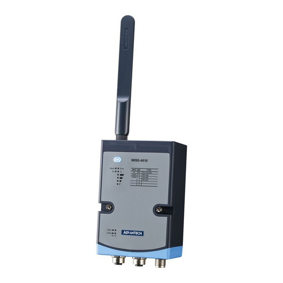
Series Family and Specifications Function Model Description LoRa Wireless I/O WISE-4610 Outdoor LoRa Wireless I/O Module Module 6 digital inputs, 1RS-485 port, and WISE-S672 1RS-232/485 port I/O Module WISE-S614 4 digital inputs and 4 analog inputs LoRa Gateway WISE-3610 LoRa Network Gateway Interface Introduction Figure 2.1 WISE-4610 Interface Introduction WISE-4610 User Manual... -
Page 15: Battery Power Switch
Battery Power Switch Open the rubber cover on the side of WISE-4610 , there is a battery switch to turn on or turn off the battery power supply. Figure 2.2 WISE-4610 Battery Switch LED Indication Figure 2.3 WISE-4610-S672 LED Indicator WISE-4610 User Manual... - Page 16 Color Indication Behavior Fast Blink (0.2 sec ON, 0.3 Wait for connecting or connecting sec OFF) Status Green Slow Blink Connecting and normal at work (0.2 sec ON, 1.8 sec OFF) Application errors. Fast Blink Network registration timeout (0.2 sec ON, 0.8 sec OFF) ...
-
Page 17: Membrane Button
Membrane Button There is one membrane button designed for WISE-4610 LoRa Wireless I/O Module on the name plate. This button used to set up different operation mode and display LED indicators. (SEE 5.1.9 for membrane button behavior) Figure 2.4 WISE-4610 Membrane Button Package Information WISE-4610 LoRa Wireless I/O Module ... - Page 18 Note! Please see WISE-6610 user manual for detail configuration of LoRaWAN gateway. Note! Micro-B USB cable for configuring WISE-4610 is available for ordering: 1700023619-01 1M micro USB type-B male to USB type-A male cable Note! M12 connector and cable for I/O or power wiring is available for order- ing: ...
-
Page 19: Chapter 3 Mechanical & Hardware Installation
Chapter Mechanical & Hardware Installation... -
Page 20: Modularization
Like all WISE-4000 series modules, WISE-4610 series of wireless sensor nodes is designed as compact units. Applicable installation methods are briefly described in the following sections. Modularization The purpose of modularization is to better leverage the same wireless board with dif- ferent I/O combination flexibly. -
Page 21: Dimension
Dimension Figure 3.2 WISE-4610 Dimension WISE-4610 User Manual... -
Page 22: Din-Rail Mounting
Figure 3.3 WISE-S600 IO Dimension DIN-Rail Mounting WISE-4610 modules can be fixed to a cabinet with mounting rails. Use a flathead screwdriver to fasten the DIN rail adapter to your module. You can then use the end brackets included in the package in order to keep it from sliding. Figure 3.4 WISE-4000 Series Mounting Kit Dimensions WISE-4610 User Manual... - Page 23 Figure 3.5 DIN-Rail Mounting Installation Figure 3.6 DIN-Rail Mounting Front WISE-4610 User Manual...
-
Page 24: Wall Mounting
Figure 3.7 DIN-Rail Mounting Back Wall Mounting The plastic wall-mounting bracket that comes with the module can be used to mount it on a wall, panel, or cabinet. Figure 3.8 Wall Mounting Installation WISE-4610 User Manual... -
Page 25: Pole Mounting
Pole Mounting For pole mounting, feed the pole-mounting ring through the hole in the middle of the module. The pole-mounting ring needs to be unlocked with a screw driver before it can be inserted through the module. To mount the module on the pole, tightly lock the pole-mounting ring. - Page 26 WISE-4610 User Manual...
-
Page 27: Chapter 4 Product Hardware Specification
Chapter Product Hardware Specification... -
Page 28: Wireless Interface
Wireless Interface Frequency Band – 868.1-869.525MHz for EU(6 channel) – 903-927.5MHz for US(16 channels) – 920.6-923.4MHz for JP(9 channels) Data Rate: See page 36 "Data Rate Configuration and Indicative Physical bit Rate" Spreading Factor: 7~12 Bandwidth: 125KHz/250KHz/500KHz ... -
Page 29: Gps
GNSS Systems GPS, GLONASS, Galileo, BeiDou, QZSS and SBAS signals Max. Update Rate Single GNSS: up to 18 Hz Concurrent GNSS: up to 10 Hz Accuracy Position: 2.5 m CEP (50% confidence) With SBAS: 2.0 m CEP (50% confidence) Acquisition Cold starts: 57 s ... -
Page 30: Power
Power Power input voltage: 10~50 V Power consumption – WISE-4610: 11W@24V, when battery charging – WISE-S614: 1.9W@24V – WISE-S672: 0.3W@24V Solar panel input voltage: 15~50 V Battery capacity: 4000mA Battery life: 6 months (data update per hour and GPS update per day) Note! The battery life is estimated in the environment at 25°C. -
Page 31: Wise-S672 I/O Module
Burn-out Detection Yes (4~20mA only) Supports Data Scaling and Averaging 4.5.2 WISE-S672 I/O Module 4.5.2.1 Digital Inputs Channels: 6 Logic level (dry contact) – 0: Open – 1: Close DI COM Non-isolation Supports 32-bit counter input function (maximum signal frequency, 200 Hz) ... -
Page 32: I/O Pin Assignment
I/O Pin Assignment Figure 4.1 WISE-S600 Pin Out Model Name WISE-S614 WISE-S672 Pin Number DI COM DI COM IA0+ DATA1- IA0- DATA1+ IA1+ IA1- IA2+ DATA2- IA2- DATA2+ IA3+ IA3- WISE-4610 User Manual... -
Page 33: Wise-S614 I/O Application Wiring
4.6.1 WISE-S614 I/O Application Wiring Figure 4.2 WISE-S614 Digital Input Wiring Diagram (port A) Figure 4.3 WISE-S614 Analog Input Wiring Diagram (port B) 4.6.2 WISE-S672 Application Wiring Figure 4.4 WISE-S672 Digital Input Wiring Diagram (port A) WISE-4610 User Manual... -
Page 34: Power Supply Wiring
Figure 4.5 WISE-S672 Serial Port Wiring Diagram (port B) Power Supply Wiring WISE-4610 modules are designed to support a standard industrial unregulated 24- power supply. For other applications, they can also accept +10 to +50 V input with 200 mV of peak-to-peak power ripple. The immediate ripple voltage should be maintained between +10 and +50 V . -
Page 35: Configuration Interface
Configuration Interface Interface: USB virtual COM port Connector: Micro-B USB USB chipset: Silicon Labs CP210x Driver: CP210x USB to UART Bridge VCP Drivers WISE-4610 User Manual... - Page 36 WISE-4610 User Manual...
-
Page 37: Product Firmware Specification
Chapter Product Firmware Specification... - Page 38 WISE-4610 is the end node of WISE link wireless network with star topology to pair with WISE-3610 Gateway. The architecture of WISE Link v1.0 Node SDK is to set the RF configuration between LoRa node and LoRa gateway without network configura- tion.
-
Page 39: Interface Design
Interface Design 5.1.1 WISE-4610 LoRa Node Interface Design Radio Frequency Radio Frequency Region 869.525 920.6 920.1 904.6 868.1 920.8 920.3 906.2 868.3 920.5 925.9 907.8 868.5 921.2 920.7 917.5 909.4 868.85 921.4 919.1 869.05 921.6 921.2 920.7 912.6 921.8 921.4 922.3 Channel... - Page 40 Tx Power Tx power Region 20 dBm 20 dBm 20 dBm 20 dBm 20 dBm 18 dBm 17 dBm 18 dBm 18 dBm 18 dBm TX Power 16 dBm 14 dBm 16 dBm 16 dBm 16 dBm 14 dBm 11 dBm 14 dBm 14 dBm...
- Page 41 Item Description The operation mode. Device Operating (Default: 1) Mode 1:WISE Link v1 2: LoRaWAN Device Class (Default: 1) Device Class 1:classA 2:classB 3:classC (Default: 2) Activation Mode 1:OTAA (Over-The-Air Activation) 2:ABP (Activation By Personalization) The AppEUI is a global application ID in IEEE EUI64 address space that uniquely identifies the entity able to process the Join- Application Identifier Req frame.
-
Page 42: Positioning
5.1.2 Positioning 5.1.2.1 General Description WISE-4610 accesses the u-blox EVA-M8M-0 GNSS module via I2C interface. This GNSS module can provide geolocation and time information. The features of EVA-M8M are listed below. Features 72-channel u-blox M8 engine GPS/QZSS L1 C/A, GLONASS L10F, Receiver type BeiDou B1 SBAS L1 C/A: WAAS, EGNOS, MSAS... -
Page 43: Led Behaviors
Configurations Item Description Positioning Enable or disable the GNSS module. (Default: Disable) Enable/Disable Position Update Time between two position fix attempts.(15 sec ~ 1 day, unit: second) Period (Default: 1 hr) Specify which GNSS signals should be processed. Value GNSS combination (Reserved) GPS+GLONASS (default) -
Page 44: Battery Charging
Signal LEDs Error LED Description (poor) (Okay) (Good) (Full) Fast RF related Error Blink Fast Blink Fast I/O error Error Blink Slow Blink Battery related error No error 5.1.4 Battery Charging The battery IC is battery fuel FLASH gauge IC for battery information. Items Values Description... - Page 45 Flags bit definitions: Content BATHI BATLOW CHG_INH RSVD OCVTAKEN SOC1 SOCF Operating OTC = Over-Temperature in Charge condition is detected. Flags Statuses True when set OTD = Over-Temperature in Discharge condition is detected. True when set BATHI = Battery High bit indicating a high battery voltage condition.
-
Page 46: Usb Vcom And Restful
Battery Events Error LED Events Condition (Slow Blink) Remaining battery capacity <= Low voltage Over-Temperature in Charge condi- battery temperature < 0°C or > tion is detected. 60°C Over-Temperature in Discharge OTD flag of Operating Sta- condition is detected. tuses set ISD flag of Operating Statuses Internal Short is detected. -
Page 47: I/O Data Format Of Wise-Link
PATCH RFC5786 defines the new HTTP/1.1 [RFC2616] method, PATCH, which is used to apply partial modifications to a resource. PATCH can be used when the client is sending one or more changes to be applied by the the server. The PATCH method requests that a set of changes described in the request entity be applied to the resource identified by the Request-URI. -
Page 48: Membrane Button
5.1.7 Membrane Button Please see LED Behavior for membrane button functionality. In "Line power only or Line power and battery"Mode When WISE-4610 is powered up via Line Power: The LED indicators are disabled in default. Accordingly, push the Membrane Button again for battery level indication. After the above, push the button again, the LED indicators will be disabled again and back to state 1. -
Page 49: Module Behavior With Different Power Supply
5.1.8 Module behavior with different power supply WISE-4610 can be powered by three different power sources: Battery, Line Power and Solar Panel. The power source detection, power fail (remove line & solar power), low-batter error LED and suspend will be different based on different power sources. Low-Battery Indicator - When battery level is equal or less than 20%, Error LED ... -
Page 50: Lorawan Function
5.1.9 LoRaWAN Function WISE-4610 can be configured through WISE-Studio for LoRaWAN Item Description Device Operating The operation mode. Mode (Default: 1) 1:WISE Link v1 2:LoRaWAN 3:Reserved for MACless 4: WISE Link v2 Device Class Device Class (Default: 1) 1:classA 2:classB 3:classC Activation Mode (Default: 2) - Page 51 Configuration parameters for LoRaWAN OTAA globally unique end-device identifier (DevEUI) Device Address (DevAddr) Application Identifier (AppEUI) Application key (AppKey) Network Session Key (NwkSkey) Application Session Key (AppSKey) WISE-4610 User Manual...
- Page 52 WISE-4610 User Manual...
-
Page 53: Product Software
Chapter Product Software Specification... -
Page 54: Connection Between Node And Gateway
Set up WISE-3610 LoRa Gateway Default IP Address: 192.168.1.1 Default User Name: root Default Password: advantech The first page of the gateway user interface displays the gateway status includ- ing System, Memory, Network, Wireless etc. WISE-4610 User Manual... - Page 55 Users can upgrade the firmware image through System/Backup/Flash Firmware After firmware upgrade, the system will reboot. Setting Gateway through WISE Manager/Management. WISE-4610 User Manual...
- Page 56 By clicking edit for further setting of WISE-3610 For WISE-Link v1.0, please ensure to disable Beacon and Periodical Join in WISE Link page to avoid the malfunction of OTAA feature. In Join tab, please also disable Timestamp and set 24h for Rejoin Period. WISE-4610 User Manual...
- Page 57 Configuration of Node in WISE Link network Please find the information for WISE-4610 Node to fill into WISE-3610 gateway. Add payload field through WISE Manager/Payload Field for AI/DI/COM config- uration. Note! Please restart the system after all configuration done WISE-4610 User Manual...
-
Page 58: Configuring Wise-4610 Lora Node By Wise Studio
Internet Explorer 10 or above 6.1.2.2 Installing WISE Studio The latest version of WISE Studio is available on the Advantech support site: http:// support.advantech.com/. To install the program, download the installation file and execute it locally. 6.1.2.3 A Brief Introduction to WISE Studio WISE Studio is a new configuration tool for WISE modules. - Page 59 Communication Box In this box, there are several communication interfaces for configuring different WISE modules. The WISE-4610 series uses the USB-serial interface for configuration. Refresh: Pressing this button refreshes the USB-serial interface. USB-Serial: This block is for connecting to a WISE module via USB. The available USB-serial port number will be shown here.
- Page 60 Power Status displays the power source and battery status. LoRa Information displays the Activation Mode/Device Address/Device Class/Data Rate. Device Information mainly tells the firmware description of the module and also the version of web page. WISE-4610 User Manual...
- Page 61 6.1.2.5 Connecting to a LoRa Network Please find the information for WISE-4610 Node through WISE studio to fill into WISE-3610 gateway. This is the information of WISE-4610, from this page, you can get every item for WISE-3610 configuration. In this page, users are allowed to set minimum 1sec data update intervals. Change of State to send data when event occurs of selected I/O is also allowed in this page.
- Page 62 WISE-4610 supports Time Synchronization Method through GPS. From this page, users can get coordinates of WISE module. GPS is included in WISE-4610, and from this page, users are allowed to select whether to enable GPS positioning or not. In default, GPS is disable for power saving purpose.
- Page 63 6.1.2.6 I/O Status Configuration Digital Input Status The value of all digital input channels can be determined from the related LED dis- play in the DI tab (green LED = "logic high"; grey LED = "logic low"). Configuration The digital input channels support several operation modes and can be configured from this page.
- Page 64 Invert Signal: WISE digital input channels support the invert digital input status function. To enable/disable this, select the Invert Signal check box on the Con- figuration page. Digital Filter: Digital input channels have a digital filter that can remove high- frequency noise.
- Page 65 reset, either by pressing Reset on the Status page or by issuing a command, it will return to the startup value, which is zero by default. If Keep Last Value is enabled, the last counter value will be kept in the register when the module is powered off.
- Page 66 COM1 (RS-485 Port) The WISE-4610 has one RS-485 port for Modbus gateway functionality; thus, you can use this port to poll data from RS-485 Modbus/RTU slave devices such as the ADAM-4000 series or ADAM-5000/485 series. Status Go the COM1 tab to check the status or to configure the RS-485 Modbus master function.
- Page 67 Modbus Configuration - Common Settings Tab In this tab, you can configure the parameters of the RS-485 port. Baud Rate: 1200, 2400, 4800, 9600, 19200, 38400, 57600, 115200 bps Data Bit: 7, 8 Stop Bit: 1, 2 ...
- Page 68 Modbus Configuration - Rule Setting Tab In this tab, you can configure the Modbus address of end devices you would like to poll. Rule: There is a maximum of 8 rules that each COM port can support. Each rule can be for a different slave device, meaning that there can be a maximum 8 of devices connected to the COM port.
- Page 69 Note! After you have changed the rule configurations, logged data in the data logger will be cleared to accommodate the new data structure of the data logger under the new configuration. Note! You can hover your mouse over the table title rows to view tooltips. Diagnostician Since different devices will have different response times, the WISE-4610 provides a diagnostics function for testing the response time of each rule.
- Page 70 You can find the latest official firm- ware releases on the Advantech support site (http://support.advantech.com/). You can also upload the configuration file or export the configuration file here.
- Page 71 WISE-4610 User Manual...
- Page 72 No part of this publication may be reproduced in any form or by any means, electronic, photocopying, recording or otherwise, without prior written permis- sion of the publisher. All brand and product names are trademarks or registered trademarks of their respective companies. © Advantech Co., Ltd. 2019...
Need help?
Do you have a question about the WISE-4610 Series and is the answer not in the manual?
Questions and answers