Table of Contents
Advertisement
Advertisement
Table of Contents

Related Manuals for Advantech WISE-4000 Series


Summary of Contents for Advantech WISE-4000 Series
- Page 1 User Manual WISE-4000 Series IoT Ethernet I/O Module...
- Page 2 No part of this manual may be reproduced, copied, translated or transmitted in any form or by any means without the prior written permission of Advantech Co., Ltd. Information provided in this manual is intended to be accurate and reliable. How- ever, Advantech Co., Ltd.
- Page 3 This product has passed the CE test for environmental specifications. We recom- mend the use of shielded cables. Technical Support and Assistance Visit the Advantech web site at www.advantech.com/support where you can find the latest information about the product. Contact your distributor, sales representative, or Advantech's customer service center for technical support if you need additional assistance.
- Page 4 The sound pressure level at the operator's position according to IEC 704-1:1982 is no more than 70 dB (A). DISCLAIMER: This set of instructions is given according to IEC 704-1. Advantech disclaims all responsibility for the accuracy of any statements contained herein.
-
Page 5: Table Of Contents
Contents Chapter Product Overview ........1 Introduction ....................2 Feature Highlights ..................2 1.2.1 RESTful Web Service ..............2 1.2.2 Data Storage Function ..............3 1.2.3 IoT Cloud Function................ 3 Series Family and Specifications ............. 4 1.3.1 Series Family ................4 Mechanical Design and Dimensions ............ - Page 6 Figure 2.14WISE-4012E Digital Input Wiring Diagram....22 Figure 2.15WISE-4012E Relay Output Wiring Diagram..... 22 2.5.3 Pin Assignment................23 Figure 2.16WISE-4012E Pin Assignment........23 2.5.4 Block Diagram ................23 Figure 2.17WISE-4012E Block Diagram ........23 WISE-4050....................24 2.6.1 I/O Specification................24 2.6.2 Application Wiring ...............
- Page 7 WISE-4050 Wireless Modbus Mapping Table ........83 WISE-4060 Wireless Modbus Mapping Table ........85 Appendix B REST for WISE-4000 Series ....87 Introduction ..................... 88 REST Resources for WISE-4000 Series..........89 B.2.1 Digital Input ................. 89 B.2.2 Digital Output ................94 B.2.3 Analog Input................
- Page 8 WISE-4000 User Manual viii...
-
Page 9: Chapter 1 Product Overview
Chapter Product Overview... -
Page 10: Introduction
Introduction WISE-4000 series is an Ethernet-based wired or wireless IoT device, which inte- grated with IoT data acquisition, processing, and publishing functions. Except various I/O type offering, WISE-4000 series provides data pre-scaling, data logic, and data logger functions. These data can be access via mobile devices and be published to cloud with security in anytime and anywhere. -
Page 11: Data Storage Function
1.2.2 Data Storage Function The internal flash of the WISE module can log up to 10,000 data samples with a time stamp. The I/O data can be logged periodically, and when the I/O status changes. Once the memory is full, users can choose to overwrite the old data to ring log or just stop the log function. -
Page 12: Series Family And Specifications
Series Family and Specifications 1.3.1 Series Family Interface Model Description 6-ch Input/Output WISE-4012E IoT Wireless I/O Module for IoT Developers 4-ch Digital Input and 4-ch Digital Output WLAN WISE-4050 IoT Wireless I/O Module 4-ch Digital Input and 4-ch Relay Output WISE-4060 IoT Wireless I/O Module 4-ch Current Input and 4-ch Digital Output... -
Page 13: Mechanical Design And Dimensions
Mechanical Design and Dimensions 1.4.1 WISE-4000 Wireless Series Dimensions 1.4.2 WISE-4000/LAN Dimensions WISE-4000 User Manual... -
Page 14: Switch
Switch Switch Description Position ON (Default) Normal Mode Initial Mode Operation Mode Dry Contact Wet Contact DI Type (all channels) Dry Contact Wet Contact Note 1 After the position 1 of SW1 been changed, user need to power on the module again to apply the operation mode Note 2 SW2 in only for WISE-4050(/LAN) and WISE-4060(/LAN), all 4 channels have to be configured to dry contact or wet contact in the same time, and... -
Page 15: Certification And Safety Standard
Certification and Safety Standard WISE-4000/LAN Series – FCC Part 15 Class A – IC ICES-003 – EN 55011 (Group 1, CLASS A) – EN 55022 – EN 61000-6-4 – EN 61000-6-2 – IEC 61000-4-2 – IEC 61000-4-3 – IEC 61000-4-4 –... -
Page 16: Package Information
Package Information WISE-4000 Wireless Series WISE-4000 Module with bundle antenna and terminal connector x1 Mounting bracket x1 Quick startup manual with China RoHS declare WISE-4000/LAN Series WISE-4000/LAN Module Mounting bracket x1 Quick startup manual with China RoHS declare ... -
Page 17: Chapter 2 Product Specifications
Chapter Product Specifications... -
Page 18: General Specification
General Specification WLAN Interface Standard Conformance: – 802.11b – 802.11g – 802.11n (2.4GHz only) Network Modes: – Limited AP (Wireless Server) – Station/Infrastructure (Wireless Client) LAN Interface Ethernet: IEEE 802.3u 10/100Base-T(X) Connector: 1-port RJ-45 General I/O Connector: 3.5mm spacing, 15-pole, plug-in screw terminal block ... - Page 19 Power Power Input Voltage: 10~30 V (24 V Standard) – WISE-4050 – WISE-4060 – WISE-4010/LAN – WISE-4050/LAN – WISE-4060/LAN USB 5V – WISE-4012E Power Consumption – WISE-4012E: 2.2 W @ 5 V – WISE-4050: 2.2 W @ 24 V –...
-
Page 20: Wise-4010/Lan
WISE-4010/LAN 2.2.1 I/O Specification Current Input – Channel: 4 – Resolution: 12-bit – Sampling Rate: 10/100 Hz/channel – Accuracy: ±0.2% of FSR @ 25°C – Input Range: 0~20 mA, 4~20 mA (Select by Web Configuration) – Input Impedance: 120 Ω –... -
Page 21: Application Wiring
2.2.2 Application Wiring Figure 2.1 WISE-4010/LAN Current Input Wiring Diagram Figure 2.2 WISE-4010/LAN Digital Output Wiring Diagram WISE-4000 User Manual... -
Page 22: Pin Assignment
2.2.3 Pin Assignment Figure 2.3 WISE-4010/LAN Pin Assignment 2.2.4 Block Diagram Figure 2.4 WISE-4010/LAN Block Diagram WISE-4050/LAN 2.3.1 I/O Specification Digital Input – Channel: 4 – Logic level –Dry Contact 0: Open 1: Close to DI COM –Wet Contact 0: 0~3 V or -3~0 V 1: 10~30 V or -30~-10 V... -
Page 23: Application Wiring
Digital Output – Channels: 4 – Open collector to 30 V, 500 mA max. for resistance load – Inductive loads require an external diode to eliminate back-EMF when the DO is turned off – Isolation: 3,000 V – On Resistance (R ): 0.7 Ω... -
Page 24: Pin Assignment
2.3.3 Pin Assignment Figure 2.7 WISE-4050/LAN Pin Assignment 2.3.4 Block Diagram Figure 2.8 WISE-4050/LAN Block Diagram WISE-4000 User Manual... -
Page 25: Wise-4060/Lan
WISE-4060/LAN 2.4.1 I/O Specification Digital Input – Channel: 4 – Logic level – Dry Contact 0: Open 1: Close to DI COM – Wet Contact 0: 0~3 V or -3~0 V 1: 10~30 V or -30~-10 V (3 mA min.) –... -
Page 26: Application Wiring
2.4.2 Application Wiring Figure 2.9 WISE-4060/LAN Digital Input Wiring Diagram Figure 2.10 WISE-4060/LAN Relay Output Wiring Diagram WISE-4000 User Manual... -
Page 27: Pin Assignment
2.4.3 Pin Assignment Figure 2.11 WISE-4060/LAN Pin Assignment 2.4.4 Block Diagram Figure 2.12 WISE-4060/LAN Block Diagram WISE-4000 User Manual... -
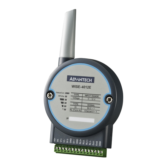
Page 28: Wise-4012E
WISE-4012E 2.5.1 I/O Specification Voltage Input – Channel: 2 – Resolution: 12-bit – Sampling Rate: 10 Hz (Total) – Accuracy: ±0.1 V – Input Range: 0~10 V – Input Impedance: 100 kΩ – Supports Data Scaling and Averaging Digital Input –... - Page 29 Note! The analog input channel of the WISE-4012E does not support inverted voltage protection, note that the input voltage should within 0~10V WISE-4000 User Manual...
-
Page 30: Application Wiring
2.5.2 Application Wiring Figure 2.13 WISE-4012E Voltage Input Wiring Diagram Figure 2.14 WISE-4012E Digital Input Wiring Diagram Figure 2.15 WISE-4012E Relay Output Wiring Diagram WISE-4000 User Manual... -
Page 31: Pin Assignment
2.5.3 Pin Assignment Figure 2.16 WISE-4012E Pin Assignment 2.5.4 Block Diagram Figure 2.17 WISE-4012E Block Diagram WISE-4000 User Manual... -
Page 32: Wise-4050
WISE-4050 2.6.1 I/O Specification Digital Input – Channel: 4 – Logic level –Dry Contact 0: Open 1: Close to DI COM –Wet Contact 0: 0~3 V 1: 10~30 V (3 mA min.) –All 4 channels should be configured to dry contact or wet contact in the same time –... -
Page 33: Application Wiring
2.6.2 Application Wiring Figure 2.18 WISE-4050 Digital Input Wiring Diagram Figure 2.19 WISE-4050 Digital Output Wiring Diagram 2.6.3 Pin Assignment Figure 2.20 WISE-4050 Pin Assignment WISE-4000 User Manual... -
Page 34: Block Diagram
2.6.4 Block Diagram Figure 2.21 WISE-4050 Block Diagram WISE-4000 User Manual... -
Page 35: Wise-4060
WISE-4060 2.7.1 I/O Specification Digital Input – Channel: 4 – Logic level –Dry Contact 0: Open 1: Close to DI COM –Wet Contact 0: 0~3 V (0.8 mA max.) 1: 10~30 V (3 mA min.) – Isolation: 3,000 V –... -
Page 36: Application Wiring
2.7.2 Application Wiring Figure 2.22 WISE-4060 Digital Input Wiring Diagram Figure 2.23 WISE-4060 Relay Output Wiring Diagram 2.7.3 Pin Assignment Figure 2.24 WISE-4060 Pin Assignment WISE-4000 User Manual... -
Page 37: Block Diagram
2.7.4 Block Diagram Figure 2.25 WISE-4060 Block Diagram WISE-4000 User Manual... - Page 38 WISE-4000 User Manual...
-
Page 39: Chapter 3 Hardware Installation
Chapter Hardware Installation... -
Page 40: Interface Introduction
Interface Introduction Mounting WISE-4000 modules are designed as compact units and are allowed to be installed in the field site under the following methods. 3.2.1 DIN-Rail Mounting The WISE-4000 module can also be fixed to the cabinet by using mounting rails. You need to assemble the DIN rail adapter to WISE-4000 module with flathead screw driver as below. - Page 41 Figure 3.3 Mounting on the DIN-Rail Figure 3.4 Rear View of DIN-Rail Mounting WISE-4000 User Manual...
-
Page 42: Wall Mounting
3.2.2 Wall Mounting Each WISE-4000 module is packed with a plastic wall mounting bracket. User can refer the bracket dimension and assembling figure to configure an optimal placement in a wall, panel, or cabinet. Figure 3.5 Mounting Kit Dimensions WISE-4000 User Manual... - Page 43 Figure 3.6 Wall Mounting Figure 3.7 Wall Mounting Finished WISE-4000 User Manual...
-
Page 44: Stack Mounting
3.2.3 Stack Mounting Figure 3.8 Stack Mounting Figure 3.9 Finished Stack Mounting WISE-4000 User Manual... -
Page 45: Wiring & Connections
Wiring & Connections This section introduces basic information on wiring the power supply, I/O units, and Ethernet connection. 3.3.1 Power Supply Wiring (Not for WISE-4012E) The system of WISE-4000 is designed for a standard industrial unregulated 24 V power supply. For further application, it can also accept +10 to +30 V of power input, 200mV peak to peak of power ripple, and the immediate ripple voltage should be maintained between +10 and +30 V... -
Page 46: I/O Units
Figure 3.11 USB Power Supply Wiring 3.3.3 I/O Units The system uses a plug-in screw terminal block for the interface between I/O mod- ules and field devices. The following information must be considered when connect- ing electrical devices to I/O modules. The terminal block accepts wires from 0.5 mm to 2.5 mm. -
Page 47: Chapter 4 System Configuration
Chapter System Configuration... -
Page 48: Connection
Connection Plug a DC power source into the +Vs, -Vs pin of WISE module to turn the power on, or plug in the USB power cable for the WISE-4012E. For WISE-4000/LAN Series, connect your computer to Ethernet port of WISE module with RJ-45 cross-over Ethernet cable, and configure the IP address of your computer as same IP domain as default IP address of module: 10.0.0.1. -
Page 49: List Of Wise-4000 Default Ethernet Ports
4.2.2 List of WISE-4000 Default Ethernet Ports Application Protocol Port Note WebServer Configurable Modbus Server Search Engine 5048 SNTP Client Randomly 4.2.3 Factory Default Settings WISE-4000/LAN Series Operation Mode: Normal Mode IP Mode: Static IP Address Default IP: 10.0.0.1 Subnet Mask: 255.0.0.0 ... - Page 50 4.2.6 Using a Browser to Configure the Module Configure URL: http://IP_address/config Default URL: WISE-4000/LAN Series: http://10.0.0.1/config WISE-4000 Wireless Series: http://192.168.1.1/config Configuration Steps Login Web Configuration Page Wirelessly connect your smart phone to your local Ethernet network and open the browser of your smart phone.
Need help?
Do you have a question about the WISE-4000 Series and is the answer not in the manual?
Questions and answers