Table of Contents
Advertisement
Advertisement
Chapters
Table of Contents

Related Manuals for horiba HP-200


Summary of Contents for horiba HP-200
- Page 1 Industrial pH Meter HP-200 Instruction Manual CODE:GZ0000214572...
- Page 2 HORIBA Advanced Techno, CO., Ltd. warrants that the Product shall be free from defects in material and workmanship and agrees to repair or replace free of charge, at option of HORIBA Advanced Techno, CO., Ltd., any malfunctioned or damaged Product attributable to responsibility of HORIBA Advanced Techno, CO., Ltd.
- Page 3 Regulations Conformable Directive This equipment conforms to the following directives and standards: Directives: the EMC Directive 2004/108/EC the Low Voltage Directive 2006/95/EC Standards: [the EMC Directive] EN61326-1: 2006 Class A, industry [the Low Voltage Directive] EN61010-1: 2001 Note When the sensor cable, transmission cable, or relay cable is extended to 30 meters or more, the surge test in the EMC Directive for CE Marking is not applicable.
- Page 4 For Your Safety Hazard Classification and Warning Symbols Warning messages are described in the following manner. Read the messages and follow the instructions carefully. Hazard classification This indicates an imminently hazardous situation which, if not avoided, will result in death or serious injury. This signal word is to be limited to the most extreme situations.
- Page 5 When the HP-200 may be subject to lightning, install a conductor rod on the output side of the HP-200 and on the side of receiving instruments.
- Page 6 Do not press any operation key with the tip of your nail or any pointed thing. Do not use organic solvent or the like. Do not immerse the HP-200 in dilute hydrochloric acid for long hours. Disposal of the Product When disposing of the product, follow the related laws and/or regulations of your country for disposal of the product.
-
Page 7: Table Of Contents
Installing the HP-200 ........ - Page 8 Daily calibration (cal mode)........Maintenance procedure for HP-200 ......
-
Page 9: Overview
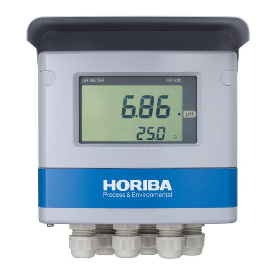
Introduction Thank you very much for purchasing our model HP-200 pH Meter for industrial use. The HP-200 allows you to make a measurement when the pH electrode and a power source for 100 V to 240 VAC are connected. The measured value and various parameters are displayed on the LCD part. When used with our cleaner, the HP-200 allows you to control the cleaner. -
Page 10: Description Of Each Part
Overview Description of each part Front view Cover This cover is used for Screw cap outdoor installation. When the two screw caps are removed, the Display part front case screws appear. The measured value and other information are displayed here. Front cover When the cover is opened, 6 operation... - Page 11 Overview Display part Status display Measured value display Status display Auxiliary display Indicator Operation key section Terminal block RS-485 terminal Electrode connection terminal Transmission output terminal and contact input terminal Power connection terminal Contact output Fuse box terminal Power switch...
-
Page 12: Description Of Operation Keys
Overview Description of operation keys The operation keys are used to change the displayed information, enter parameters, or perform calibration. The displayed value or item can be changed when it blinks. Select a blinking value or item with the keys and then press the ENT key. The setting will flash, indicating that it has been established. -
Page 13: Description Of Indicator
Overview Description of indicator Status display Turns ON when the hold mode becomes active. HOLD indicator Starts blinking when contact input is received or when the hold mode becomes active due to an error CAL indicator Turns ON when the cal mode becomes active. EXT1 indicator Turns ON when contact input such as the cleaning signal is received CLN indicator Turns ON when the cleaning output contact signal is output... -
Page 14: Description Of Operation Modes And Menu Items
Overview Description of operation modes and menu items The HP-200 offers 3 kinds of operation modes and 4 kinds of menus. Operation mode <Meas mode> In this mode, measurements and control are performed. <Cal mode> In this mode, calibration is performed. - Page 15 Overview Modes and menus avaialble from meas mode <Meas mode> The measurement output is held. <Hold mode> Hold down the HOLD key <Setup menu> See P. 30. [ ] key See P. 39. <Cal menu> [ ] key (ph/temperature calibration) See P.
- Page 16 Overview <Meas mode> <Hold mode> (Hold down) (Hold down) Setup menu menu Check contact output User Check menu Check cleaning Check the calibrated value Check the controlled value...
-
Page 17: Installation
Installation Installation Installation environment To ensure the use of the HP-200 in stable condition, install the HP-200 in a location where the following requirements are met: HP-200 The location shall be well ventilated. The ambient temperature shall be between -20°C and 55°C both inclusive. -
Page 18: Installing The Hp-200
Installation Installing the HP-200 The HP-200 can be installed on a pole (50A) or a wall. Installation on a pole View of the HP-200 installed on a pole Maintenance area [Unit: mm] Installation on a wall View of the HP-200 installed on a wall... -
Page 19: Installing The Electrode
1. Be sure to provide a bypass line on the piping line. Note Unless there is a bypass line, the HP-200 must be stopped when the maintenance or replacement of the electrode is carried out. 2. Use the distribution type holder with its output side open to atmospheric air. -
Page 20: Procedures For Connections
Procedures for connections Opening the cover for the HP-200 1. Remove two screw caps located on the upper part of the front of the HP-200. Carefully store the removed caps. 2. Open the front cover. 3. Loosen four screws located on the front of the HP-200. Check that the screws are floated by springs. -
Page 21: Connecting The Power Source
Provide the power switch in a place near the HP-200 so that the power can be turned ON/ OFF. WARNING If lightning might strike, install an arrester on the output side of the HP-200 and on the side of receiving instruments. Electric shock hazard Be sure to check that no power is supplied before starting work. -
Page 22: Connecting The Contact Output Terminal
CAUTION When the HP-200 is OFF, the C-NC contact for R1 to R4 is short-circuited. Therefore, be careful about the connection of load. As illustrated below, connect the contact output:... -
Page 23: Connecting The Contact Input Terminal And The Transmission Output Terminal
The applicable electric wire is of 2 mm (AWG14) maximum. For the transmission output cable, use a shielded cable. When lightning might strike, install an arrestor on the output side of the HP-200 and on the side of receiving instruments. OUT1 OUT2 EXT.IN... -
Page 24: Connecting The Communication Terminal
Installation Connecting the communication terminal Connecting the RS-485 terminal The HP-200 has an RS-485 communication terminal. To use this terminal, connect wiring. The applicable electric wire is of 0.14 mm to 2.5 mm (AWG26 to 14). For the communication output cable, use a twisted shielded pair. -
Page 25: Connecting The Electrode Cable
Installation Connecting the electrode cable Cautionary instructions for electrode cable The pH electrode cable is highly insulated. In handling this cable, pay attention to the following points: Do not wet any cable terminal or the terminal block with water or the like; also do not soil it with dirt, oil, or the like. - Page 26 A liquid junction resistance error can be detected by selecting "gr" in“ Set sensor self-check ” (page 32) on the Setup menu. Temperature compensation electrode For the HP-200. one of the following four kinds of temperature compensation electrodes can be used: Ω...
- Page 27 (C-5A-YT2-PS or C-5A-YT2-PSE) exclusively for the electrode cable; and our relay box (CT-25pH) for exclusive use. The electrode cable is extendable up to 50 meters between the HP-200 and the electrode. It is recommended that the dedicated relay cable be housed in a conduit pipe to prevent static electricity from being generated due to induction, vibration, or any other reason.
- Page 28 Installation 7. Strip each of the lead wires so that its copper wire end is exposed about 1 cm. In stripping the covering of a conductive wire, take care not to cut the conductive wire. Cover each of braided shields 1 and 2 with a shrinking tube to avoid short-circuit. Braided shield 1 Braided shield 2 Lead wire: Transparent...
-
Page 29: Operation
Operation Operation Preparation for operation When first using the HP-200 after it has been shipped from factory or reset to the factory settings, perform the following work: Checking the wiring Initial setup Calibration Checking the wiring Check the following points: The power cable (transmission cable) and the electrode cable are connected properly. - Page 30 Initial setup The HP-200 was shipped in the initial state from factory. Even if the HP-200 is in the initial state, the basic use is possible. To make any change, follow the instructions given in“ Setup menu ” (page 30)
- Page 31 Operation Setup menu Screen Ref. Description Initial value item display page “C.rng“ Set current range for transmission output 1 0-14 “rng.0“ Set range zero for transmission output 1. 0.00 Settings for “rng.S“ Set range span for transmission output 1. 14.00 transmission “C.HoLd“...
-
Page 32: Measurement
Measurement Measurement Meas mode 1. Turn ON the power. The measurement object is displayed on the display part. A measurement range is also displayed with the Meas mode selected. The measurement is started with the measured value displayed. In the Meas mode, this is the normal state. 2. - Page 33 Measurement Turn ON the power <Meas mode> Displayed for a few seconds <Meas mode> Contact output check setup screen (Example with "r1" and "AL" selected) Controlled value setup screen Delay time setup screen Establishes Changes the the value value Cancels the value Cleaning check screen Cleaning wait time check screen...
- Page 34 Measurement <Meas mode> Calibration data check screen (Example of 2-point calibration display) Displays calibration point Displays zero (STD) value Displays span (SLOPE) value Displays the elapsed number of days for calibration Moving average setup screen Establishes the Changes the value value Cancels the value...
- Page 35 Measurement Table 1 Items displayed in Meas mode Screen 1 Screen 2 Condition Description Action Remarks The temperature The measured With Measured may not be values for pH and temperature value display displayed temperature are display screen depending on the displayed.
- Page 36 Measurement Screen 1 Screen 2 Condition Description Action Remarks When The delay time is Input range Delay time "HoLd" is displayed or set in screen 0 to 600 seconds selected seconds. Indicates that data Output during is output during When "CLn" cleaning cleaning and in is selected...
- Page 37 Measurement Screen 1 Screen 2 Condition Description Action Remarks Calibration Indicates the data check calibration points for Note: For manual screen calibration data (this input ("PH.Adj"), Calibration display example "Adj" is displayed point check assumes two-point on the display part. screen calibration) Indicates...
-
Page 38: Setup Menu
Measurement Setup menu The Setup menu allows you to specify your electrode type, measurement conditions, display parameters, calibration method, and transmission output. Entering the Setup menu 1. In the meas mode, hold down the HOLD key until the [HOLD] indicator turns ON. 2. - Page 39 Measurement Table 2 <Items displayed on Setup menu Setting Initial Screen 1 Screen 2 Description Remarks range value Set the moving Set the moving average count. average count 1 to 50 Change the value when the measured (damping factor). value is not stable enough. This setting determines whether the hold mode automatically returns to the meas mode.
- Page 40 "non": Performs no self-check Note: "gr" is only available for the electrode with liquid grounding. This setting determines whether electrode terminals R and SE are connected inside the HP-200. "cLoSE": Shorts the circuit between R Set R-SE "cLoSE", "cLoS and SE.
-
Page 41: Set Temp Display
Measurement Setting Initial Screen 1 Screen 2 Description Remarks range value Select a calibration method. Normally "Auto" should be selected. Set calibration "Auto", "Auto" For three-point calibration or type "bASic" calibration using a special standard solution, set this parameter to "bASic. Specify a calibration point. -
Page 42: Set Contact Output Type ("R3" Or "R4)
Measurement Setting Initial Screen 1 Screen 2 Description Remarks range value Specify a contact output type. "non": No output "non", "CtrL": Control output "CtrL", "AL": Warning output Set contact output "AL", "non" "tPS": Time-sharing proportional type ("r1" or "r2") "tPS", control (shift function) "tPF", "tPF": Time-sharing proportional... - Page 43 Measurement Setting Initial Screen 1 Screen 2 Description Remarks range value Set minimum ON Specify minimum ON time in seconds. time 2 to 10 (when contact Note: This setting is only displayed when output type is set contact output type is set to "tPS" or "tPF." to "tPS"...
- Page 44 Measurement Setting Initial Screen 1 Screen 2 Description Remarks range value "opt" 0-14, Specify a transmission output range for 0-10, transmission output 1. Set current range 0-8, for transmission 2-12, 0-14 Note: An arbitrary value may be specified output 1 3-11, when transmission output range is set to 4-14,...
- Page 45 Measurement Setting Initial Screen 1 Screen 2 Description Remarks range value −20.0 to Set range zero for Specify a temperature value for 4 mA for transmission 130.0 transmission output 2. output 2 (°C) −20.0 to Set range span for Specify a temperature value for 20 mA for transmission 130.0 100.0...
- Page 46 Measurement Setting Initial Screen 1 Screen 2 Description Remarks range value Specify whether cleaning output is enabled or disabled. Set cleaning "yES", "yES" output "no" "yES": Enables cleaning output. "no": Disables cleaning output. Specify a cleaning output type. "nor": Provides cleaning output in accordance with the cleaning output frequency and the cleaning time.
-
Page 47: Calibration Menu
Measurement Calibration menu Entering the Calibration menu allows you to calibrate the pH electrode or the temperature electrode, or to manually enter the calibration value for the pH electrode. Entering the calibration menu You can enter the calibration menu by either of two methods. This section describes the method of entering this menu from the hold mode. - Page 48 Measurement Table 3 Items displayed on the Cal menu Calibration Screen 1 Screen 2 Description Action Remarks Type Immerse the pH First screen with electrode in the the calibration type [ENT] key: Next screen standard solution set to "Auto" for pH7. The measured Screen displayed After stability detection,...
- Page 49 Measurement Calibration Screen 1 Screen 2 Description Action Remarks Type CAL key: Changes the number of First screen calibration points displayed for one- Immerse the pH point calibration [ / ] key: electrode in the when the Changes a standard solution. calibration type is calibration point "bASic"...
- Page 50 Measurement Calibration Screen 1 Screen 2 Description Action Remarks Type CAL key: Changes First screen the number of Immerse the pH displayed for two- calibration points electrode in the point calibration [ / ]: Changes the standard solution for when calibration calibration point the first point.
- Page 51 Measurement Calibration Screen 1 Screen 2 Description Action Remarks Type The measured Screen displayed value blinks and the during stability left indicator detection of third changes standard solution incrementally. Screen displayed [CAL]: Restarts when the stability detection The measured measurement of value and all of the [ / ] key: Selects "bASic"...
-
Page 52: User Check Menu
Measurement User check menu Entering the User check menu allows you to check the display part or the transmission output or to initialize the settings. Entering the User check menu 1. Hold down the HOLD key in the meas mode until the HOLD indicator turns ON. 2. - Page 53 Measurement Table 4 Items displayed on the User check menu Screen 1 Screen 2 Description Action Remarks The whole LCD is Screen to check the illuminated, allowing you to check the display. This screen allows you to Screen to check relay check that relay 1 ("r1") output 1 turns ON/OFF...
- Page 54 Measurement Screen 1 Screen 2 Description Action Remarks [ ] key: Allows you to check output of Screen to check 4 mA is output to 12 mA transmission output transmission output 1 and (to check output of 4 [ ] key: Allows you to check output of 3.8 mA [ ] key: Allows you...
-
Page 55: Calibration
Measurement Calibration Calibration is classified into pH calibration and temperature calibration. Note After the power has been first turned ON or the electrode has been replaced, be sure to perform calibration with a standard solution. pH calibration pH calibration is classified into three kinds: auto, basic, and manual. Reference For selecting auto or basic calibration, see “... - Page 56 Measurement 3. Press the ENT key. The pH cal mode is selected with the Auto or Basic cal screen displayed. Carry out calibration in accordance with the operation procedure for auto or basic calibration described on the next and subsequent pages. To cancel the calibration during its process, press the ESC key.
- Page 57 Measurement 3. To perform the second-point calibration, immerse the electrode in the standard solution for pH4 or pH9 and then wait in this state or press the ENT key. The second-point calibration will be started. 4. When the reading becomes stable enough, the second-point calibration is finished. Once the stability is determined as acceptable, the measured value stops blinking and the second-point calibration is finished.
- Page 58 Measurement Basic calibration Use this calibration when you want to perform any calibration method other than the two-point calibration for pH4 and pH7 or for pH7 and pH9. It also allows you to achieve a known pH value. Items to be supplied 1 to 3 kinds of standard solutions Two or three kinds of standard solutions that have a difference of 2 pH minimum between them when two- or three-point calibration is performed.
- Page 59 Measurement 4. Press the ENT key. The auxiliary display part will blink and the calibration of the first point will be finished. (Now the one-point calibration is complete.) The one-point calibration updates only the zero (STD) value. For the calibration of two points or more, immerse the electrode in the standard solution for the second points.
- Page 60 Measurement 6. Press the ENT key. The auxiliary display part will blink and the calibration of the third point will be finished. Now the three-point calibration is complete. For 3-point calibration At this point, the new calibration value is applied. Now the pH basic calibration is complete.
-
Page 61: Temperature Calibration
Measurement Temperature calibration The temperature calibration is used to correct temperature. Note Immerse the electrode in a solution at a known temperature and then well expose it to the water temperature. When you enter the hold mode, transmission output becomes the output value specified on the Setup menu. -
Page 62: Ph Calibration By Manual Input
Measurement pH calibration by manual input For this calibration, manually enter the calibration value for pH. Operation procedure Enter the manual input pH cal mode from the meas mode. 1. Hold down the HOLD key in the meas mode until the HOLD indicator turns ON. The hold mode will become active with HOLD displayed on the upper left part. - Page 63 Measurement To cancel the calibration during its process, press the ESC key. You will return to the Cal menu with no calibration data updated. To subsequently set any other calibration parameter, press the [ / ] key to select the parameter to be set.
-
Page 64: Contact Output
Measurement Contact output Specify a control action for each of R1, R2, R3, and R4. The available control items vary depending on the selected output type. The items marked with a circle are available for display as options. Selected type Screen Description "non"... - Page 65 Measurement Contact output types The following contact output types are available: "non": No contact output This setting provides no contact output. "CtrL": Control output When the measured value is larger than (control value plus control width x 1/2), the control output is turned ON to drive the metering pump so that the chemical agent is injected.
- Page 66 Measurement "AL": Alarm output When the measured value becomes larger than the setting, the alarm output is turned ON to trigger the alarm after the delay time. When the measured value becomes smaller than the setting, the output is immediately turned OFF to cancel the alarm. (The above case is applicable for the upper-limit operation;...
- Page 67 Measurement "tPS": Time-sharing proportional control (shift function) Time-sharing proportional control means variably controlling the output by changing the ON/OFF proportion within a certain period in accordance with the deviation (difference between control value and measured value) in order to perform proportional control for a metering pump for pH control or a control device such as a solenoid valve.
- Page 68 Measurement "tPF": Time-sharing proportional control (F-zone function) Time-sharing proportional control means variably controlling the output by changing the ON/OFF proportion within a certain period in accordance with the deviation (difference between control value and measured value) in order to perform proportional control for a metering pump for pH control or a control device such as a solenoid valve.
- Page 69 Measurement When control method is set to "Hi," the ON/OFF time is calculated using the equation below: t = Ct x (measured value - SEt) / Pb When t is smaller than Lt, t = Lt; when t is larger than (Ct x oL/100), t = (Ct x oL/100);...
-
Page 70: Cleaning Output
Measurement Cleaning output The selected cleaning output (CLN output) is provided under the following conditions With or Internal "CLn" "HoLd" External Cleaning without Cleaning cleaning period contact contact contact input output*1 Transmission cleaning output (during cleaning output*2 output*3 (ON: (ON: output*2 output type "typE"... -
Page 71: Output Conditions For Various Output Types
Measurement Output conditions for various output types The output conditions for various output types are shown below: Fail output Transmission output FAIL When Self-check measured When Contact Cleaning When error value temperature Status output output Transmission output 1 Transmission output 2 occurs deflects from is abnormal... -
Page 72: Information For Accurate Measurements
Information for accurate measurements Information for accurate measurements This chapter provides information on maintenance in order to ensure the highest accuracy and best use of the HP-200. It describes accuracy maintenance including the daily calibration. Daily calibration (cal mode) The method of daily performing calibration is described below: Note Do not reuse any standard solution. -
Page 73: Maintenance Procedure For Hp-200
Note When a cleaner is installed, stop its operation and then perform the maintenance of the electrode. Turn OFF the HP-200 or hold down the HOLD key to enter the hold mode and then start the maintenance. View of pH electrode alone... -
Page 74: Adding Kcl Internal Solution
Information for accurate measurements WARNING Strong acid hazard If dilute hydrochloric acid gets into your eye, its mucosa may be irritated, leading to blindness. In handling hydrochloric acid, be sure to wear protective goggles, protective gloves, and a protective mask. If dilute hydrochloric acid gets into your eye, immediately rinse the eye with a large quantity of water for more than 15 minutes. -
Page 75: Storage
Information for accurate measurements Storage Ensure that the tip (glass membrane) and the liquid junction of the electrode are not dried. Fill the provided protective cap with tap water and then put the cap on the electrode tip for storage. In addition, tightly close the internal solution filling inlet to prevent internal drying. Replacing the electrode CAUTION The electrode is made of glass and broken when exposed to impact or strong force. - Page 76 Information for accurate measurements Electrode Electrode packing Stop point 9. Remove the protective cap for the electrode and the tape for the KCl filling inlet on the electrode. Tape for KCl filling inlet Electrode Note Unless the tape for the filling inlet on the electrode is removed, no measurements can be made successfully.
- Page 77 Information for accurate measurements 15. Slightly draw the cable packing out of the holder packing. Holder cap Holder cap Cable packing Cable packing Holder Holder 16. Open the internal solution filling inlet by about one third.Now the electrode is ready for use.
-
Page 78: Troubleshooting
The electrode cable is improperly wired. Check for any loosened screws on the terminal In particularly, there is electrical block in the HP-200 and that in the relay box and discontinuity in the G- or R-line. for any wrong wiring. -
Page 79: Error Codes
Troubleshooting Error codes The HP-200 has a capability of displaying various error codes. An error code is displayed on the auxiliary display part while blinking. Description of error codes Priority Display levels of Error Description Occurs during errors Response speed... -
Page 80: Remedial Action For Error Codes
Troubleshooting Remedial action for error codes When an error code is displayed, take remedial action in accordance with the table below: Error code Trigger condition Reset condition Possible cause Remedial action Press the ESC The electrode is dirty. Clean the electrode. key. - Page 81 Troubleshooting Error code Trigger condition Reset condition Possible cause Remedial action When temperature If the resistance value sensor is set to 500 or The resistance between T does not fall within the left 1k, its resistance value and T of the electrode is range, the electrode is Ω...
- Page 82 Turn OFF the power and then turn it ON The internal system in the again. Turn OFF the power and HP-200 is abnormal. then turn it ON again. The stored data such as E-91 If the system error does settings and calibration...
-
Page 83: Remedial Action For Ph Electrode's Fault
Troubleshooting Remedial action for pH electrode's fault If our pH electrode becomes faulty, take remedial action in accordance with the following table. If the pH electrode is not rectified after taking the remedial action, contact us. Symptom Remedial action Possible reason Cracking of glass Replace the electrode as it is membrane/comparison... -
Page 84: Self-Check Capability For Ph Electrode
Troubleshooting Self-check capability for pH electrode The HP-200 has a self-check capability for the pH electrode. This capability detects any cracking of the glass response membrane of the electrode or any clogging of the comparison electrode (liquid junction). It may not work depending on the electrode type or the operating environment. -
Page 85: Cases Where The Self-Check Capability Does Not Work Properly
Troubleshooting Cases where the self-check capability does not work properly. The self-check capability may not properly work depending on the electrode type or the operating environment. This section describes the cases where this capability does not work properly. Case where the electrode is not wetted by the solution under measurement. If the electrode does not come into contact with the sample, the self-check capability does not work properly. - Page 86 The self-check capability does not work properly because of its operating principle. In this case, disable this capability when using the HP-200. Even if the glass response membrane has cracking, the response membrane error (E-71) may not occur.
-
Page 87: Reference Data
Reference data Reference data Specifications Product name pH meter Model HP-200 Combined sensor Glass electrode pH0 to pH14 (display range: pH-1 to pH15) 0°C to 100°C Measurement When the automatic detection capability for temperature sensor types is range Temperature used: Display range: -10°C to 110°C When temperature sensor type is manually set: Display range: -20°C to 130°C... - Page 88 Reference data Setting range :0.00 pH to 14.00 pH ON/OFF Control width :0.02 pH to 4.00 pH (±0.01 pH to ±2.00 pH) Setting range :0.00 to 14.00 pH Proportional band :0.02 pH to 4.00 pH Period: 5 to 300 seconds Control output shift function: 0% to 50% of the period can be shifted.
- Page 89 Reference data Calibration Calibration method Auto or basic calibration Number of calibration Selectable from 1, 2, and 3 points points Kinds of standard solu- pH 2, 4, 7, 9, and 10 tions Arbitrary standard solution (with difference of 2 pH min.) for basic calibration Additional capabilities Automatic detection of kind of standard solution Automatic detection of electric potential stability...
-
Page 90: Information On Standard Solutions
Information on standard solutions The HP-200 allows you to perform calibration using five kinds of standard solutions. The pH values of pH standard solutions at each temperature are shown in the table below: pH2 standard... -
Page 91: List Of Parts
Reference data List of parts Optionally available parts Part name Model Description CH-101 series Immersed type holder HIBX series Immersed type holder for tip replaceable electrode (617X series) CF-301 series Distribution type holder (pressurization type) Holder CF-401S Distribution type holder (pressurization type/SUS stainless steel) Distribution type holder for tip replaceable electrode (617X CF-501 series) - Page 92 Reference data Description Temperature Part name Model Operating Liquid-junction Length of Type compensation temperature structure lead wire element 0 °C to 6110-50B General-purpose 60°C Ceramic junction -10 °Cto 6108-50B Tough 100°C -10°C to 6109-50B Touch sleeve Sleeve 80°C 6151-50B For hydrofluoric acid resistance 6152-50B For high-alkaline resistance Pt 1 kΩ...
-
Page 93: Disposal Method
Reference data Disposal method To dispose of the HP-200, comply with the ordinances and regulations specified in your region. The parts for the HP-200 are made of the following raw materials: Name Raw material Name Raw material Nameplate Switch information plate... - Page 94 Reference data Name Raw material Name Raw material Printed circuit board (H4W- Printed circuit LCD holder ADC12 ANL-0x) board Case packing PTFE plate PTFE Plunger packing R Protective sheet U Parallel pin SUS304 Upper hinge ADC12 Terminal information plate Screw cap 2 Terminal block information Functional ground information plate...
- Page 95 Headquarters 31, Miyanonishi-cho, Kisshoin, Minami-ku, Kyoto, 601-8306 TEL:+81-75-321-7184 FAX:+81-75-321-7291 Tokyo Office 4F Higashikanda Fukoku Seimei Building, 1-7-8, Higashikanda, Chiyoda-ku, Tokyo, 101-0031 TEL:+81-3-3851-3150 FAX:+81-3-3851-3140 Nagoya Office 6F Sumitomo Seimei Chikusa 2nd Building, 3-15-31, Aoi, Higashi-ku, Nagoya, 461-0004 TEL:+81-52-937-0812 FAX:+81-52-937-0675...
Need help?
Do you have a question about the HP-200 and is the answer not in the manual?
Questions and answers