Table of Contents
Advertisement
Quick Links
Advertisement
Table of Contents
Troubleshooting

Related Manuals for horiba HR-200RT


Summary of Contents for horiba HR-200RT
- Page 1 Residual Chlorine Monitor HR-200RT Instruction Manual CODE:GZ0000361153...
- Page 2 HORIBA Advanced Techno, Co., Ltd. warrants that the Product shall be free from defects in material and workmanship and agrees to repair or replace free of charge, at option of HORIBA Advanced Techno, Co., Ltd., any malfunctioned or damaged Product attributable to responsibility of HORIBA Advanced Techno, Co., Ltd.
- Page 3 For Your Safety Hazard classification and warning symbols Warning messages are described in the following manner. Read the messages and follow the instructions carefully. Hazard classification This indicates an imminently hazardous situation which, if not avoided, will result in death or serious injury. This signal word is to be limited to the most extreme situations.
- Page 4 Safety precautions This section provides precautions to enable you to use the product safely and correctly and to prevent injury and damage. The terms of DANGER, WARNING, and CAUTION indicate the degree of imminency and hazardous situation. Read the precautions carefully as it contains important safety messages.
- Page 5 Product Handling Information Operational precautions Use of the equipment in a manner not specified by the manufacturer may impair the protection provided by the equipment. And it may also reduce equipment performance. Do not press any operation key with the tip of your nail or anything pointed. Do not use solutions such as organic solvents.
- Page 6 Manual Information Description in this manual Note This interprets the necessary points for correct operation and notifies the important points for handling the unit. Reference This indicates the part of where to refer the information. This indicates reference information. Term Definition This document uses the following terms as defined: Term Definition...
-
Page 7: Table Of Contents
Contents Overview ..........Unpacking. - Page 8 Measurement ......... . Meas mode .
- Page 9 Technical data ..........What is residual chlorine? .
-
Page 11: Overview
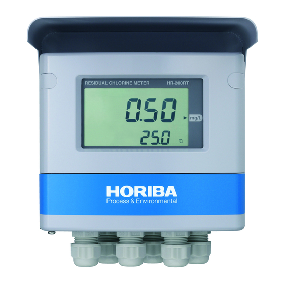
This is a residual chlorine meter with no chemical treatment to the sample. The main components are the transmitter HR-200RT, the detector unit, measuring cell and some peripheral units. It is suitable to monitor the residual chlorine concentration for those samples;... -
Page 12: Unpacking
Overview Unpacking Upon delivery of this product, unpack it immediately and check the contents for completeness. In addition, check this product for any damage at the same time. Breakdown of complete set Converter.....1 U bolt.......... 2 (With a bracket and a cover) (U bolt: 2, M8 nut: 4, Spring washer: 4, Flat washer: 4) Instruction manual (this book).. -
Page 13: Structure Of Residual Chlorine Meter
Overview Structure of residual chlorine meter Converter (190) Display Conduit Front cover *: (size) is approximate. [Unit: mm] Detector unit RA-30 Detector Measuring cell (140) (140) *: (size) is approximate. [Unit: mm]... -
Page 14: Example Of Tap Water Cradle
Overview Example of tap water cradle Converter Detector Sampling cock Measuring cell Flow switch Ball valve Filter housing Sample inlet Sample outlet Ball valve 3 Rc3/4 Rc3/4 φ14 foundation bolts (4 pcs.) 500 mm or more 500 mm or more maintenance space maintenance space (350) -
Page 15: Names And Functions Of Each Part
Overview Names and functions of each part Converter Front panel Hood This hood is used for outdoor Screw cap installation. When the two screw caps are removed, the front case screws appear. Display section The measured value and other information are displayed here. Front cover When the cover is opened, six operation keys appear. - Page 16 Overview Display section Status display Main display Status display Sub display Indicator Operation key section Terminal block Transmission output terminal RS-485 terminal Communication terminal Sensor terminal Contact input terminal 2 Contact input terminal 1 Contact output terminal Power terminal Fuse box Power switch...
-
Page 17: Detector Unit
Detector unit Detector Measuring cell (1) Connector cable This is used for connecting with the converter (HR-200RT). (2) Reference electrode (3) Anode electrode Note If an impact is applied, the electrodes could be damaged. Be extremely careful when cleaning the measuring cell or replacing the cathode electrode. -
Page 18: Description Of Operation Section
Overview Description of operation section Description of operation keys Operation keys are used to switch displays, enter settings, and perform calibration. You can change the value or item while the display is blinking. Select a currently blinking value or item with / , and press ENT. -
Page 19: Description Of Operation Modes And Menu Items
Overview Description of operation modes and menu items Modes and menus from the meas mode Meas mode Performs measurement and control. Press Contact output check Refer to page 28. Press Press Press Press Calibration value check Refer to page 29. Allows you to check the calibration values during measurement. -
Page 20: Installation
Installation Installation Installation environment Followings are the conditions of the installation of the converter and the detector unit. Converter Well-ventilated location. Ambient temperature in the range of −20°C to 55°C. Spilled water does not adversely affect the location. Not exposed to direct sunlight. Heat is less likely to be generated. -
Page 21: Installation Method
Installation Installation method Converter The HR-200RT can be installed on a pole (50 A) or a wall. Spaces for opening the front case are required. Installation on a pole [Unit: mm] Installation on a wall Slotted hole of 4-10 × 11... -
Page 22: Piping
Installation Piping The size of the sampling tube for the half union attached on the measuring cell should be φ8 mm × φ6 mm. If you do not use the half union you have to provide a joint with R1/8 thread. -
Page 23: Sample Outlet Piping
Installation Sample outlet piping Correct piping installation procedure Keep the end of piping under an open-air environment. Install the piping as short as possible so that back pressure can not be applied (1). If the distance up to the drain ditch is long, create an open-air section along the way and then install horizontal piping using a pipe of 20 A or above (2). -
Page 24: Flow
Installation Flow Detector unit Detector unit Drain Sump pit Solenoid valve Sample inlet Regulator Flow adjustment Regulator Filter valve Flow switch Activated carbon filter Sample outlet Note The zero filter (activated carbon filter) should be placed close to the sensor. It takes a time to be a reduced residual chlorine concentration at the sensor if the pipe between the zero filter and the sensor is long. -
Page 25: Option Unit
Installation Option unit Filter housing (RA-F) Install a filter housing following the flow control valve if the sample water includes dust or suspended solid. The PVC 16 mm nominal pipe should be used to the filter housing connectors. The filter in the filter housing must be replaced at least every 3 months as a recommendation. -
Page 26: Wire Connection
Installation Wire connection Opening the cover for the converter 1. Remove the two screw caps located on the top on the front of the converter. Carefully store the removed screw caps. 2. Open the front cover. 3. Loosen the four screws located on the front of the converter. Check that these screws are pushed up by the spring force for connectiong wires without falling off. -
Page 27: Power Supply
Installation Power supply WARNING If there is a possibility of a lightning strike, install an arrester on the output side and receiving instrument side of the converter. Electric shock hazard Be sure to turn OFF the power before wiring power source. A power switch is equipped beside the terminal block. -
Page 28: Contact Output R1 To R3
Installation Contact output R1 to R3 WARNING To connect any load exceeding the contact capacity or any induction load (e.g., motor, pump), be sure to use a power relay. The contact capacity is below 250 V AC 3 A or 30 V DC 3 A (resistance load). R3 is below 30 V DC 1 A (resistance load). -
Page 29: Transmission Output
Installation Transmission output WARNING If there is a possibility of a lightning strike, install an arrester on the output side and receiving instrument side of the converter. The terminal screws of the input/transmission output are M3.5 type. The applicable electric wire is 2 mm (AWG14) max. - Page 30 Connect a terminating resistor (Rt: 120 Ω) to the terminal of the RS-485 communication line. One-on-one communication should take place between the converter (HR-200RT) and HP-200. Set the HP-200 address to “1”. For the address setting, refer to the instruction manual for the industrial-use pH converter (HP-200).
-
Page 31: Detector And Connector Cable Connection
Front view Extending the connector cable When extending the connector cable, be sure to use the following parts manufactured by HORIBA Advanced Techno: Dedicated extension cable (C-7E) Dedicated relay box (CT-20RC) The maximum extension distance between the converter and detector is 10 m. -
Page 32: Operation
Operation Operation Preparation for operation When you operate the instrument at the first time, be sure to complete the following preparation. Check of converter and detector installation condition. (Refer to “ Installation method ” (page 11)) Check if the wirings are correct. (Refer to the “ Wire connection ” (page 16)) Are the terminal block screws firmly tightened? Is the fluctuation of the power supply voltage within ±10% of the rated voltage? Check if the piping for mistake. - Page 33 Operation Setting Initial Refer Display Item Description range value to page The measured residual chlorine value is corrected according to the specified pH value. 5.8 to 8.6 pH correction value Note: setting (pH) This is displayed when “pH correction function setting”...
- Page 34 Operation Setting Initial Refer Display Item Description range value to page Contact output setting: R1 to R3 The other relays can be set in the same manner. r1 to r3 Reference Refer to “ Control targets and their available options ” (page 37) for the options available for the selected control target.
- Page 35 Operation Setting Initial Refer Display Item Description range value to page Input the preset value for current holding. Note: Preset value setting for 0.00 to PrES 3.00 This is displayed when “Transmission output hold transmission output 1.A 5.00 (mg/L) (current hold) setting for transmission output 1.A” is set to “PrES”.
- Page 36 Operation Setting Initial Refer Display Item Description range value to page E.in1 External input 1 setting FLo, HoLd, tyPE Contact input type setting Specify the contact input type. rng, CAL Specify whether to enable or disable the flow switch input. Flow switch input function FLo.in yES, no...
-
Page 37: Measurement
Measurement Measurement Meas mode 1. Turn the power ON. The measurement target appears on the main display. The measurement range is then displayed and the system enters the meas mode. After the measured value is displayed, measurement starts. This is the normal meas mode. 2. - Page 38 Measurement Table 1 List of items displayed in the meas mode Display Display condition Item Description Setting range Displays the measured residual chlorine concentration When (mg/L) and temperature (°C). temperature Main display screen Note: display is The temperature may not be displayed depending on the available setting.
- Page 39 Measurement Display Display condition Item Description Setting range Calibration data check screen Calibration data check screen No calibration Screen for no Indicates that there is no previous data calibration data calibration data. Displays the zero point deviation of a Zero value check sensor using the residual chlorine screen concentration (mg/L).
-
Page 40: Setup Menu
Measurement Setup menu The setup menu allows you to set the measurement conditions, display method, calibration method, and transmission output. Entering the setup menu 1. In the meas mode, hold down HOLD until the HOLD indicator turns ON. 2. Press to display “SEt”... - Page 41 Measurement Table 2 List of items displayed for the setup menu Setting Display Item Description range Parameter setting Moving average count Increase dF to reduce the variations of the measured data: 1 to 120 (damping factor) Decrease dF to speed up the response. (times) setting It is possible to change the damping factor in the meas mode.
- Page 42 Measurement Setting Display Item Description range Specify what to display on the sub display when the power is turned ON or the hold mode is returned to the meas mode. non: No display r1: Displays an alarm value or assignment for relay 1 r2: Displays an alarm value or assignment for relay 2 r3, r2, r3: Displays an alarm value or assignment for relay 3...
- Page 43 Measurement Setting Display Item Description range Specify whether or not to display an automatic zero calibration attempt error (E-13). yES: Displays E-13 and also outputs a contact if zero calibration fails because the value is not stabilized within the automatic zero calibration time.
- Page 44 Measurement Setting Display Item Description range Specify the delay time in seconds from when an alarm or hold state occurs until a contact is output. If the alarm is cancelled, the contact will be immediately cancelled Contact output delay 0 to 600 without delay.
- Page 45 Measurement Setting Display Item Description range Specify the output during burnout of the transmission output 1.A when an error occurs during measurement. out.20: Outputs 21 mA at the time of burnout Transmission output out.20, 1.A burnout hold out.4, out.4: Outputs 3.8 mA at the time of burnout setting non: No burnout setting Note:...
- Page 46 Measurement Setting Display Item Description range Holds the preset value. −10.0 to Transmission output 2 Note: hold output value 110.0 This is displayed when “Transmission output hold (current hold) (preset) setting (°C) setting for transmission output 2” is set to “PrES”. Specify the output during burnout of transmission output 2.
- Page 47 Measurement Contact output Control targets and their available options Make the setting referring to the table shown below. Displayed options vary depending on the settings shown in gray. Items with a check mark are available for selection. Table 3 Control targets and their available options Description Selected type Control direction setting...
- Page 48 Measurement AL: Alarm output When the measured value is higher than the set value, the contact is output (ON) after the delay time and an alarm occurs. When the measured value falls below the set value, the output is immediately stopped (OFF) and the alarm is cancelled.
- Page 49 Measurement Output conditions for each output type The output conditions for various output types are shown below. Transmission output Transmission output (Cur2) Contact (Cur1.A, Cur1.b) output C.HoLd C.HoLd FAIL output setting FAIL output HoLd PrES HoLd PrES b.out b.out Power OFF Opened (ON) When normal operation Valid...
- Page 50 Measurement *1: The error alarm is turned ON/OFF as follows: When it is ON, CF-NCF is open; when it is OFF, CF-NCF is closed. *2: The zero solution calibration, span calibration, and temperature calibration by key operation are included. *3: E-13 is not displayed when "SEt" - "CAL" - "CAL.E" is set to "no". *4: out.4 or out.20 *5: 3.80 mA or 21 mA...
-
Page 51: Cal Menu
Measurement Cal menu The cal menu allows you to perform calibration of the residual chlorine and temperature. Entering the cal menu You can enter the cal mode either by holding down CAL or from the hold mode. This section describes the method of entering the cal menu from the hold mode. 1. - Page 52 Measurement Table 4 List of items displayed for the cal menu Calibration Setting Initial Display Item Description type range value Zero solution calibration Reference Refer to “ Zero calibration ” (page 54). Zero point calibration is performed using a zero solution. Screen displayed Pass the zero solution through the sensor Zero...
-
Page 53: User Check Menu
Measurement User check menu The user check menu allows you to check the display section or the transmission output, or to initialize the settings. Entering the user check menu 1. In the meas mode, hold down HOLD until the HOLD indicator turns ON. 2. - Page 54 Measurement Display Item Description The ON/OFF status for relay 3 (r3) can be checked. Relay output 3 ENT: Switches between ON and OFF check screen Note: When the system enters this mode, the contact output is set to OFF. The ON/OFF status of FAIL can be checked. FAIL output check ENT: Switches between ON and OFF screen...
-
Page 55: Maintenance
Maintenance Maintenance Perform the maintenance and inspection procedures in order to maintain the residual chlorine meter in a good condition for an extended period of time. The maintenance cycle varies depending on the usage environment or water quality condition. When the operation is initially started, use the cycle indicated in “Periodic inspection list” as a guide. -
Page 56: Converter Maintenance Procedure
Maintenance Converter maintenance procedure Check the transmitter of the following points. Cable gland loosing LCD display The lack of LCD display can be checked in the User check mode. Dew on the window inside Open the cover and dry out the inside of the transmitter. Terminal screw loosing Note Seal the cable gland packing and cover packing tightly to avoid the ambient air coming in the... -
Page 57: Detector Unit Maintenance Procedure
Maintenance Detector unit maintenance procedure This section describes the maintenance procedures for the residual chlorine detector. Checking the sample flow rate Fluctuations in the sample water flow rate affect the reading of the residual chlorine sensor. A decrease in the flow rate due to clogging of the piping could cause a decrease in the reading value. -
Page 58: Removing The Detector Contamination
Maintenance Removing the detector contamination Physical polishing/cleaning using ceramic beads is performed for the detector unit. If any hard-to-remove contamination adheres to the cathode electrode surface, it may largely affect the measurement results. If the reading value drops or any abnormality is visually detected, clean the cathode electrode according to the following procedure. - Page 59 Maintenance 5. Rinse off the contamination from the surface of the cathode electrode. WARNING Beware of strong acid When handling nitric acid, be sure to wear protective goggles and gloves. If it gets into your eyes, it could cause irritation to the mucous membrane and the loss of eye sight. In order to avoid this, immediately rinse your eyes with a large quantity of running water for at least 15 minutes and quickly seek medical help.
-
Page 60: Cleaning/Replacing The Bead Filter A, Bead Filter And Ceramic Beads
Maintenance Cleaning procedure for other electrodes wipe the surface of the anode and cathode electrode with absorbent cotton wetted by alcohol. Note The silver chloride will deposit on the surface of the anode electrode according to the progress of measurement. Too thick silver chloride layer will reduce the contact area of the silver and the sample water, then the electrons which cover the cathode reaction will not be sufficient. -
Page 61: Cleaning The Measuring Cell
Maintenance Cleaning the measuring cell Since water stain adheres to the inside of the measuring cell as time goes along, clean it periodically. 1. Detach the connector cable to stop cathode rotation. 2. Close the valve to stop the sample supply. 3. -
Page 62: Restarting The Measurement
Maintenance Restarting the measurement 1. The inside of the detector may be contaminated while the operation is paused. Remove the contamination of the detector, clean/replace the bead filter A, bead filter, clean the measuring cell, and replace the filter (option) as necessary. Refer to “... -
Page 63: Calibration
Maintenance Calibration There are three types of calibration: zero solution calibration, span calibration, and temperature calibration. You have to confirm the reading is stable before calibration. Residual chlorine concentration calibration There are two types of residual chlorine calibration: zero solution calibration and span calibration. - Page 64 Maintenance Zero calibration Zero solution refers to a sample whose residual chlorine concentration is 0.00 mg/L. Zero solution calibration can be performed with higher accuracy by passing the zero solution through the measuring cell. 1. Switch to the cal mode by performing the operation described in “ Calibration ” (page 53), and to the zero solution calibration screen.
- Page 65 Maintenance 3. To check the last calibration. Press one time to see the period from the last calibration. one time 4. To check the time to the next calibration. Press ENT one time to see the time left to the next calibration. one time Span calibration For span calibration, electrical zero calibration is initially performed automatically.
- Page 66 Maintenance 6. Press ENT. The sub display starts flashing. A new calibration value is applied at this point. This completes the span calibration. The display will return to the cal menu or hold mode. When calibration is performed after entering When calibration is performed the span cal mode by holding down CAL from the cal menu...
-
Page 67: Temperature Calibration
Maintenance Temperature calibration If the deviation of temperature reading from the calibrated thermometer is over 0.2°C calibrate the temperature. Note Check the temperature of the currently running sample and ensure the sensor is able to accurately read the water temperature. When the hold mode is activated, the transmission output will be equal to the output value specified in the setup menu. -
Page 68: Troubleshooting
Supply the clean instrument air from the air purge supply inlet. operation gas, etc. The power supply voltage is Check the power supply voltage. Power outside the rated voltage range does not Wiring error Check the power distribution line. turn ON Internal error of the converter Contact HORIBA Advanced Techno. -
Page 69: Measurements Exceeding The Measurement Range
Check that the concentration is within the measurement range by Blinking display performing manual analysis, etc. Concentration is high (outside the If the concentration is within the measurement range, contact HORIBA measurement Advanced Techno. range) Temperature sensor error Perform temperature calibration. - Page 70 Troubleshooting Error Error occurrence Error description Contents Occurrence display priority Communication line with the HP-200 is not E-86 HP-200 connection error During measurement connected and calibration E-87 Motor rotation error The sensor motor rotation is faulty E-90 Converter internal communication error The contents of the memory, such as setting Anytime E-91...
-
Page 71: Troubleshooting For Error Codes
Troubleshooting Troubleshooting for error codes If an error code is displayed, take an appropriate action according to the following troubleshooting list. Cancellation Error code Occurrence condition Possible cause Remedial action condition E-11 Cancelled Current exceeding ±0.8 Calibration has not been (Zero μA flows between A and performed correctly or... - Page 72 A and cancelled Sensor error correct it to a normal condition. The sensor is K is high damaged E-80 Converter (HR-200RT) Wiring error of the (Sensor and detector (RA-30) are Check the wiring. connector cable disconnection) not connected...
-
Page 73: Data
Data Data Specifications Converter Product name Industrial-use residual chlorine meter Model HR-200RT Sensor type RA-30 Concentration 0 mg/L to 3 mg/L (Display range: 0 mg/L to 5 mg/L) Measurement range Temperature 0°C to 50°C (Display range: -10°C to 110°C) Concentration 0.01 mg/L... - Page 74 Data Contact type Open collector no-voltage “a” contact Contact input ON resistance: 100 Ω (max.) Condition Open-circuit voltage: 24 V DC Short-circuit current: 12 mA DC (max.) Selectable from among the external input for transmission output Contact function hold, flow switch input for interlock (open when the flow rate drops), and calibration command Type RS-485...
-
Page 75: Detector Unit
Data Note Although an arrestor (400 V discharge starting voltage) is mounted for the transmission output, contact input, and communication, install an optimum surge absorber element on the connection line, depending on the surrounding environment, device installation conditions, and externally connected devices. -
Page 76: Cathode Electrode
Data *3: Measurement cannot be performed correctly when the electrical conductivity falls below 8 mS/m (80 μS/cm). Be sure to perform measurement in the above conditions. *4: If the electrode is exposed to the direct sunlight, the anode and cathode electrode could deteriorate. Install the instrument where it is not exposed to direct sunlight (indoors). -
Page 77: Zero Filter
Data Zero filter Product name Zero filter unit Model RA-ZF Operating range 0.1 L/min to 0.5 L/min Material of liquid contact section PVC, EPDM, PMMA Operating temperature 0°C to 50°C (no freezing) Primary pressure 0.1 MPa to 0.2 MPa sample inlet and outlet φ8 mm × φ6 mm tube Piping connection Mass Approx. -
Page 78: Technical Data
Data Technical data What is residual chlorine? Residual chlorine refers to hypochlorous acid, which is generated when a chlorine agent is dissolved with water, and chloramine, which is generated when hypochlorous acid is combined with ammonia. The former one is called “free residual chlorine”, and the latter one is called “combined residual chlorine”, and they are collectively called “residual chlorine”. -
Page 79: Measurement Principle
Data Measurement principle The measuring principle of the HR-200RT is three-electrode polarograph method. Gold is used for the cathode electrode and silver/silver chloride is used for the anode electrode and for the reference electrode. This method can control the potential difference to be constant between cathode electrode and the sample with reference electrode as a probe of detecting sample potential. -
Page 80: Sample Liquid Conditions
Data Sample liquid conditions Influence of the pH of the sample The chemical form of free residual chlorine varies depending on the pH of the sample, as described in the previous section. Fig. 3 indicates variations in the readings of the converter due to a change in the pH values. As indicated in Fig. - Page 81 Data Influence of the temperature of the sample With the polarographic method adopted by the converter, readings are affected by the temperature of the sample. There are two reasons for this fact: (1) as the diffusion coefficient depends on the temperature, the obtained diffusion current also changes (2) the chemical equilibration of the hypochlorous acid depends on the temperature.
-
Page 82: Parts List
Data Parts list Options Model Part name Remarks Part number Filter housing 3200471048 RA-F Flow switch Setting value: 0.3 L/min 3200519040 RA-FS30 Flow meter 100 mL to 500 mL 3200471238 RA-FM30 RA-ZF Zero filter 3200436685 RA-ZCH Manual zero calibration 3200471015 RA-ZC100V Automatic zero calibration 3200443720... -
Page 83: Disposing Of The Instrument
Data Disposing of the instrument Dispose of this product in accordance with local laws, ordinances and regulations. Parts of this product are made of the following materials. Converter 25 26 27 28 29 30 Name Material Name Material Nameplate Switch ID plate Front cover ADC12 Terminal cover L... - Page 84 Data Name Material Name Material Printed circuit board H4W- Printed circuit LCD holder ADC12 ANL-0x board Case packing PTFE plate PTFE Plunger packing R Protective sheet U Parallel pin SUS304 Upper hinge ADC12 Terminal nameplate Screw cap 2 Terminal block information Functional ground information plate plate...
-
Page 85: Detector Unit (Ra-30)
Data Detector unit (RA-30) Detector and measuring cell Name Material Name Material Anode assembly PPO + Ag + EPDM Bead cell Desiccant Filter Nylon O-ring (S28) Ceramic beads Ceramic Shaft SUS304 Filter Nylon HIGH-STICKER Bead cell O-ring (S80) EPDM O-ring (S36) Sensor base Measuring cell Motor... -
Page 86: Quick Reference
Data Quick reference (appendix) Quick reference is a digest of the instruction manual. - Page 93 Headquarters 31, Miyanonishi-cho, Kisshoin Minami-ku, Kyoto, 601-8306 TEL:+81-75-321-7184 FAX:+81-75-321-7291...
Need help?
Do you have a question about the HR-200RT and is the answer not in the manual?
Questions and answers