Table of Contents
Advertisement
Quick Links
Advertisement
Chapters
Table of Contents

Related Manuals for horiba HU-200SS SS-90


Summary of Contents for horiba HU-200SS SS-90
- Page 1 MLSS meter HU-200SS SS-90 Instruction Manual CODE:GZ0000230907...
- Page 2 HORIBA Advanced Techno, CO., Ltd. warrants that the Product shall be free from defects in material and workmanship and agrees to repair or replace free of charge, at option of HORIBA Advanced Techno, CO., Ltd., any malfunctioned or damaged Product attributable to responsibility of HORIBA Advanced Techno, CO., Ltd.
- Page 3 Regulations Conformable Directive This equipment conforms to the following directives and standards: Directives: the EMC Directive 2004/108/EC the Low Voltage Directive 2006/95/EC Standards: [the EMC Directive] EN61326-1: 2006 Class A, industry [the Low Voltage Directive] EN61010-1: 2001 Note If the sensor cable, transmission cable, or relay cable is extended to 30 m or more, the surge test in the EMC Directive for CE Marking is not applicable.
- Page 4 For Your Safety Hazard Classification and Warning Symbols Warning messages are described in the following manner. Read the messages and follow the instructions carefully. Hazard classification This indicates an imminently hazardous situation which, if not avoided, will result in death or serious injury. This signal word is to be limited to the most extreme situations.
- Page 5 Safety Precautions This section provides precautions to enable you to use the product safely and correctly and to prevent injury and damage. The terms of DANGER, WARNING, and CAUTION indicate the degree of imminency and hazardous situation. Read the precautions carefully as it contains important safety messages.
- Page 6 Product Handling Information Operational Precautions Use of the equipment in a manner not specified by the manufacturer may impair the protection provided by the equipment. And it may also reduce equipment performance. Therefore, exercise the following precautions: Do not press any operation key with the tip of your fingernail or with any pointed object. Do not use organic solvents or the like.
-
Page 7: Table Of Contents
Contents Overview ..........Overview of equipment . - Page 8 Zero calibration Cal mode........Selecting the sample properties-specific working curves ... . Checking the zero calibration data .
-
Page 9: Overview
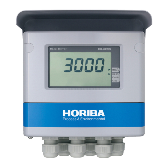
Overview Overview Overview of equipment Thank you very much for purchasing our Industrial-Use HU-200SS SS-90 MLSS Meter. This Industrial-Use MLSS Meter consists of a HU-200SS converter and a SS-90 immersion type detector. With this MLSS Meter, a wide range (from 0 mg/L to 20000 mg/L) of SS contents can be measured with excellent reproducibility using the near-infrared-radiation transmission method. -
Page 10: Content
Overview Features of the detector Built-in CPU and ADC Data communication with the converter Near-infrared radiation transmission method with stable sensitivity PFA sensor head to which dirt does not adhere easily 3 types of built-in working curves Long-life LED light sources, and the elimination of ambient light by blinking Light source monitoring capability provides high stability Content Items included... -
Page 11: Description Of Each Part (Converter)
Overview Description of each part (converter) Front view Cover Hood for outdoor Screw cap installation When the two screw caps are removed, the Display front case screws can be seen. The measured value and other information is displayed here. Front cover When the cover is opened, There are 6 operation keys. - Page 12 Overview Display Status display Measured value display Status display Auxiliary display Indicator Operation key section Terminal block RS-485 terminal Detector connection terminal Transmission output terminal Contact input terminal Power connection terminal Contact output Fuse box terminal Power switch...
-
Page 13: Description Of Operation Keys
Overview Description of operation keys The operation keys are used to toggle between displayed information, to enter any setting values, or to perform calibration work. When the indication is blinking, the figures and parameters can be changed. Use the ▲/▼ (UP/DOWN) key to select a blinking value or item, and then press the ENT key. The setting will flash and then be established. -
Page 14: Status Display
Overview Status display Status display Representation Display in text Description/Operation (meaning) Illuminated in the Hold mode (when the transmission output is held). HOLD Starts blinking when contact input is received or when the hold mode becomes active due to an error. Illuminated when the Cal mode becomes active. -
Page 15: Description Of Operation Modes And Menu Items
Overview Description of operation modes and menu items This equipment offers three types of operation modes and four types of menus. Operation mode Meas mode In this mode, samples are measured, and transmission signals and relays are controlled. Cal mode This mode allows you to perform zero calibration and span calibration. - Page 16 Overview Each mode and menu from Meas mode Meas mode The measurement output is held. Hold mode Hold down the HOLD key. See page 27. Setup menu ▼ key See page 32. Cal menu ▼ key (MLSS calibration) User Check menu See page 34.
- Page 17 Overview Meas mode Hold mode Hold down Hold down Setting Menu Check the contact output. Calibration Menu User Check Menu Check the calibration data. Adjust a moving average.
-
Page 18: Installation
Installation Installation Installation environment To ensure the stable use of the HU-200SS SS-90 condition, install the HU-200SS SS-90 in a location that meets the following requirements. Instrument mainframe The location should be well ventilated to prevent build-up of moisture. The ambient temperature should be between −20°C and 55°C. -
Page 19: Installing The Hu-200Ss
Installation Installing the HU-200SS This instrument can be mounted on a pole (50 A) or on a wall. Installation on a pole View of the HU- 200SS mounted on a pole Maintenance [Unit: mm] area Installation on a wall 4-10 × 11 slot View of the HU- 200SS mounted on a wall... -
Page 20: Procedures For Connections
Installation Procedures for connections Opening the converter cover 1. Remove the two rubber-made screw caps located on the upper part of the front of the converter. Do not lose the removed screw caps that will be reattached after the work. 2. -
Page 21: Connecting The Power Source
The applicable electric wire is of 0.75 mm to 5.5 mm (AWG18 to AWG10). Put the power switch in a place near the HU-200SS SS-90 so that the power can be turned ON/OFF easily. WARNING If there is a possibility of a lightning strike, install an arrester on the output side of the converter and on the side of receiving instruments. -
Page 22: Connecting The Contact Output Terminal
Installation Connecting the contact output terminal The contact capacity is lower than 250 V AC, 3 A or 30 V DC, 3 A at a resistance load. The terminal screw for the contact output is M4. The applicable electric wire is of 0.75 mm to 5.5 mm (AWG18 to AWG10). -
Page 23: Connecting The Transmission Output Terminals
Installation Connecting the transmission output terminals The terminal screws for transmission output is of M3.5. The applicable electric wire is 2 mm (AWG 14) max. For the transmission output cable, use a shielded cable. If there is a possibility of a lighting strike, install an arrester on the output side of this instrument and on the side of receiving instruments. -
Page 24: Connecting The Communication Terminal
Installation Connecting the communication terminal Connecting the RS-485 terminal The HU-200SS SS-90 has an RS-485 communication terminal. To use this terminal, connect the wiring. The applicable electric wire is 0.14 mm to 2.5 mm (AWG26 to AWG14). For the communication output cable, use a twisted shielded pair cable. -
Page 25: Connecting The Detector Cable
Installation Connecting the detector cable Precautions for the detector cable Turn OFF the power source during the connecting work. For maintenance, the detector will need to be pulled up. For this reason, provide enough wiring to allow for this. Lay down the detector cable along a route that is adequately separated from the vicinity of any equipment that may cause induction in the motors, etc. -
Page 26: Detector Installation Method
Installation Detector installation method Two types of holders for installing the detector have been standardized. Immersion-type holder The detector is maintained at the tip of a holder, and the holder is immersed in a sample. Drop-type holder The detector is passed through the inside of a holder fixed in place, and only the detector is raised and lowered. - Page 27 Installation For a drop-type holder Pass the detector through a holder, drop the holder in measured liquid, and set up the holder while the tip of the detector is soaked in the measured liquid. Set up the detector at a location where it can be easily pulled up or maintained. Use a SUS-made drop-type holder if the holder length exceeds 2 m.
-
Page 28: Operation
Operation Operation Preparation for operation When this equipment is used for the first time, perform the following. Wiring check Check the installation status of sensors. Initial settings (the selection of working curve, settings for transmission signals, and settings for operating conditions of relay contacts) Calibration (zero calibration) (Calibration after reset is not needed because calibration information is stored on the sensor side and is called up to the screen under energized conditions.) - Page 29 Operation Initial setup The converter is shipped with initial settings from the factory. If there is a need to change any initial settings, follow the instructions given in “ Entering the Setup menu ” (page 27). For the initial settings, see the table below. Setting Screen Initial...
- Page 30 Operation Note Before starting operation, be sure to make settings for the following items. Select a working curve type. (Selectable from MLSS, Clay, and Kaolin)
-
Page 31: Measurement
Measurement Measurement Meas mode 1. Turn ON the power. The measurement object is displayed on the measured value display. The measurable range is displayed with the Meas mode selected. If the detector is operating normally, measurements will be automatically started and measured values will be displayed on the screen. - Page 32 Measurement Meas mode *Setup menu If "non" is selected from the "diSP" setting items, nothing is displayed in the sub-display part after returning to the Meas mode. Controlled value setup menu Establishes Setting the value Change Cancels the value Alarm settings can be changed during measurement.
- Page 33 Measurement Table 1 List of items displayed in Meas mode Screen 1 Screen 2 Condition Description Action Remarks 」 A measured value is displayed. Relay Setting When rly Conditions screen "- - - - " indicates type is (The numeral at the Relay 1 is not used.
- Page 34 Measurement Screen 1 Screen 2 Condition Description Action Remarks Cleaning This screen shows "- - - - " indicates "non" that cleaning output that a relay is not Setting is not used. used. The time up to next cleaning start is 10 h or longer are Cleaning output shown in hours,...
-
Page 35: Setup Menu
Measurement Setup menu The Setup menu allows you to select any parameters, working curves of the detector, display settings, transmission output, relays and communication addresses. Entering the Setup menu 1. In the Meas mode, hold down the HOLD key until the HOLD indicator lights up. 2. -
Page 36: Para" "Ret.t" Set Auto Return Time. 2
Measurement Table 2 List of display items in the Setup menu Setting Initial Screen 1 Screen 2 Description Remarks range value Set the moving Increase dF to reduce the variations in 1 to 50 average count measured values. Decrease dF to times (damping factor) speed up the response. -
Page 37: Type" Set Contact Output Types ("R1" And "R2"). "Non
Measurement Setting Initial Screen 1 Screen 2 Description Remarks range value Set contact output type (Type). "non"; No output Relay 1 "non" "AL": Enables an alarm triggering Relay 2 "AL" contact. "nor" Set ontact output "HoLd" "HoLd": Outputs a contact during types ("r1","r2") "CLn"... -
Page 38: C.rng" Set A Range Of Transmission Output (Current Range). 10000
Measurement Setting Initial Screen 1 Screen 2 Description Remarks range value Setting for a "2000" Full-scale transmission output can be range of "5000" 0 to selected. In the options, zero and a transmission "10000" 10000 point in the full scale can be arbitrarily output "20000"... -
Page 39: Type" Timing Of Cleaning Start (Type) "Or
Measurement Setting Initial Screen 1 Screen 2 Description Remarks range value Setting to enable or disable the "no" Specify whether to output active voltage "no" use of cleaning "yES" contact for cleaning. contact. Select a combinational operation between the internal timer and the external directive for cleaning. -
Page 40: Cal Menu
Measurement Cal menu In the Cal menu, zero calibration and span calibration of the MLSS detector is preformed. Since the transmission method is adopted, the zero point might change due to dirt, but span sensitivity does not change. It is recommend to check the zero point at regular intervals. For span calibration, obtain the correlation between a measured value and an analyzed value in a certain period during which concentration fluctuates, and enter a coefficient. - Page 41 Measurement Table 3 List of items displayed on the Cal menu Calibration Screen 1 Screen 2 Description Action Remarks Type Wash the sensor head beforehand. Place the The current sensor head in a bucket measured value filled with water, and wait for blinks.
-
Page 42: User Check Menu
Measurement User check menu Entering the User Check menu allows you to check the display part or the transmission output, or to initialize the settings. Entering the User Check menu 1. In the Meas mode, hold down the HOLD key until the HOLD indicator lights up. 2. - Page 43 Measurement Table 4 List of items displayed on the User Check menu Screen 1 Screen 2 Description Action Remarks The whole LCD is Screen to check the illuminated, allowing you to check the display. Screen to check ON/OFF check of relay 1 relay output 1 ("r1") is possible.
- Page 44 Measurement Screen 1 Screen 2 Description Action Remarks Note that the setting values and span Screen for Initialization of calibration value Screen for setting data and span revert to default initialization of calibration data. Select values. setting data and Upon completion of "yES"...
-
Page 45: Contact Output
Measurement Contact output Specify control operation for each of R1 and R2. The control items that can be specified vary depending on the selected output type. The items marked with a circle will be displayed as options. Selected type Screen Description "nor"... - Page 46 "CLn": If cleaning output is set to "trg", entering this output to the contact input of a same series of HORIBA Advanced Techno converters makes it possible to perform the chain motions of cleaning (to perform cleaning operation at different time shifted by each converter). For example, if this motion is used, there is no need to take into consideration a decrease in the pressure of water sources or air sources for water cleaning or air cleaning.
-
Page 47: Output Conditions For Various Kinds Of Output
Measurement Output conditions for various kinds of output The output conditions for various output types are shown below. Failure output (Opened/Closed Transmission output Contact output between CF-NCF) Cleaning r1, r2 Status output Self-check Over Burnout Burnout F.SC F.oF None Enabled HoLd Power-off Opened... -
Page 48: Cleaning Output
Measurement Cleaning output Cleaning output (CLN output) is output in accordance with the following conditions. "CLn" "HoLd" Cleaning Internal External Cleaning Cleaning Contact Contact output cleaning cycle contact input output *1 Transmission output output *2 output *3 Yes/No output Cleaning: ○ ON: ○... -
Page 49: Information For Accurate Measurements
Information for accurate measurements Information for accurate measurements This chapter provides information on maintenance aimed at ensuring accuracy, such as calibration methods. Zero calibration Cal mode Zero calibration is an operation adjusting the value of clean water to zero. The factors of zero point fluctuations, such as dirt on the sensor head or the deterioration of light sources, can be eliminated by zero calibration. -
Page 50: Selecting The Sample Properties-Specific Working Curves
Information for accurate measurements Selecting the sample properties-specific working curves The MLSS meter has the capability of analyzing a SS value to adjust another value to the SS value and the capability of selecting three types of working curves according to sample properties in advance. -
Page 51: Checking The Zero Calibration Data
Information for accurate measurements Checking the zero calibration data On the Calibration Data Check screen, checks can be made of the amount of transmitted light for zero calibration and the number of days elapsed since the date of the last zero calibration. A check of the amount of transmitted light makes a comparison with the initial amount of transmitted light. -
Page 52: Span Calibration
Information for accurate measurements Span calibration Span calibration matches a measured value with an analyzed value. Since the span sensitivity of the light transmission method does not change, it is not intended to calibrate variations in sensitivity on the instrument side. A span coefficient is calculated to obtain a correlation between a measured value and an analyzed value, and to match a measured value to an analyzed value. - Page 53 Information for accurate measurements Span calibration procedure Span calibration enters a coefficient that was calculated beforehand. In a situation where an analysis can be made on site, it is possible to take a sample in a bucket on site and adjust the coefficient to the analyzed value. Put the converter in the span calibration mode.
-
Page 54: Maintenance Of The Detector
Information for accurate measurements Maintenance of the detector Cleaning the detector The shape of the sensor head is such that dirt, etc. does not easily adhere to it. However, if there is heavy dirt, or if a decrease in the amount of zero light occurs, perform the cleaning work. -
Page 55: Troubleshooting
The power supply voltage falls outside the Check the power supply voltage. rated voltage range. Check the power wiring. There is no power. There is a wiring problem. Contact us. The HU-200SS SS-90 has an internal problem. -
Page 56: Measurements Exceeding The Measurable Range
Troubleshooting Measurements exceeding the measurable range If an SS measured value is outside the measurement range (below −200 mg/L or above 20000 mg/L [above 22000 mg/L in the case of range cut]), the measured value is displayed as blinking. Take remedial action as instructed below. Symptom Possible cause Remedial action... -
Page 57: Error Code
Troubleshooting Error code The HU-200SS SS-90 has the capability of displaying various error codes. A blinking error code is displayed on the auxiliary display. More than two types of errors cannot be displayed. If multiple errors occur, higher priority errors are displayed in the order in which they occur frequently. -
Page 58: Reference Data
Reference data Reference data Specifications Converter Industrial-use MLSS meter Product name Converter type HU-200SS industrial-use MLSS converter SS-90 MLSS detector for industrial use Detector type Activated sludge (MLSS) 0 to 20000 mg/L (MLSS) Measurable range 0 to 10000 mg/L (white inorganic powder) Kaolin Clay(inorganic mud) 0 to 20000 mg/L (gray inorganic mud) - Page 59 Reference data Number of output points Output type Active voltage contact output (connected supply voltage output) Contact type Relay contact, SPST (1a) Contact capacity 250 V AC, 3A, 30 V DC, 3 A (resistance load) Contact capability Solenoid valve drive for cleaning Cleaning 0.1 h to 168.0 h frequency...
- Page 60 Reference data EMCDirectives (2004/108/EC) EN61326-1:2006 CE marking Low Voltage Directives (2006/95/EC) EN61010 -1:2001 Electrostatic discharge IEC61000-4-2 Electromagnetic radiation radio frequency IEC61000-4-3 field Electric fast transient/burst IEC61000-4-4 Immunity Industrial Serge IEC61000-4-5 (*1) location Applicable Conduction obstruction induced by radio standards IEC61000-4-6 frequency Voltage dip, short time blackout, voltage IEC61000-4-11...
- Page 61 Reference data Detector Product name MLSS detector for industrial use Model SS-90 Measuring principle Light transmission method Light source Infrared LED, 880 nm, approx. 10 Hz, AC blinking Detector (transmitted light/reference light) Cell length Approx. 7 mm Data transfer RS-485 (communication with the converter) Self-check Water immersion detection Operating...
-
Page 62: Measuring Principle
The relational expression showing a MISS concentration and a MLSS absorbance has been obtained by HORIBA Advanced Techno through sampling. Sensitivity may vary slightly depending on the type of activated sludge. Span calibration is available as the capability of adjusting a measured value to a analyzed value. -
Page 63: Disposal Method
Reference data Disposal method To dispose of the HU-200SS SS-90, comply with the applicable ordinance or regulations specified by your local government. The parts for the HU-200SS SS-90 are made of the following materials: Name Material Name Material Nameplate Switch ID plate... - Page 64 Reference data Name Material Name Material Printed circuit board (H4W- Printed circuit LCD holder ADC12 ANL-0x) board Case packing PTFE plate PTFE Plunger packing R Protective sheet U Parallel pin SUS304 Upper hinge ADC12 Terminal ID plate Screw cap 2 Terminal block information Functional ground information plate...
-
Page 65: Table Of Mlss Meter's On-Screen Display
Reference data Table of MLSS meter's on-screen display Display English Addr Adress Alarm A.rEt Auto return b.out Burn out CaL.dAt Calibration data Calibration menu Clean CLn.t Cleaning type 1.CLn.t Cleaning type of 1 2.CLn.t Cleaning type of 2 Clear Curr Current C.HoLd Current hold... - Page 66 Reference data PtnA Pattern A Ptnb Pattern B PtnC PatternC PrES Preset rng.C Range cut rng.S Range span rng.0 Range zero Relay Relay 1 Relay 2 rEt.t Return time RS485 SenSor Sensor Setting menu SPAn Span calibration S.diSP Sub-display Trigger to next tyPE Type User check menu...
- Page 67 Headquarters 31, Miyanonishi-cho, Kisshoin, Minami-ku, Kyoto, 601-8306 TEL:+81-75-321-7184 FAX:+81-75-321-7291 Tokyo Office 4F Higashikanda Fukoku Seimei Building, 1-7-8, Higashikanda, Chiyoda-ku, Tokyo, 101-0031 TEL:+81-3-3851-3150 FAX:+81-3-3851-3140 Nagoya Office 6F Sumitomo Seimei Chikusa 2nd Building, 3-15-31, Aoi, Higashi-ku, Nagoya, 461-0004 TEL:+81-52-937-0812 FAX:+81-52-937-0675...
Need help?
Do you have a question about the HU-200SS SS-90 and is the answer not in the manual?
Questions and answers