Table of Contents
Advertisement
Advertisement
Table of Contents

Related Manuals for horiba HT-110


Summary of Contents for horiba HT-110
- Page 1 Total Organic Carbon Analyzer HT-110 Instruction Manual CODE:GZ0000139064A...
- Page 2 ■ Warranty and Responsibility HORIBA ADVANCED TECHNO warrants that the Product shall be free from defects in material and workmanship and agrees to repair or replace free of charge, at HORIBA ADVANCED TECHNO’s option, any malfunctioned or damaged Product attributable to HORIBA ADVANCED TECHNO’s responsibility for a period of one (1) year from the delivery...
- Page 3 Conformable Directive This equipment conforms to the following directives and standards: The EMC Directives 2004/108/EC in accordance with Article 10 (1) Directives: of the Directive. The Low Voltage Directive 2006/95/EC Standard: [The EMC Directive] EN61326-2-3: 2006 (Emission: Class A, Immunity: for Industry location) [The Low Voltage Diretive] EN61010-1: 2001 This equipment shall not be used in the residential, commercial and light-industrial environment.
- Page 4 For your safety Warning messages are described in the following manner. Read the messages and follow the instructions carefully. ● Meaning of warning messages This indicates an imminently hazardous situation which, if not avoided, will result in death or serious injury. This signal word is to be limited to the most extreme situations.
- Page 5 ■ Safety Precautions This section provides precautions to enable you to use the product safely and correctly and to prevent injury and damage. The terms of DANGER, WARNING, and CAUTION indicate the degree of imminency and hazardous situation. Read the precautions carefully as it contains important safety messages.
- Page 6 Points of concern Use of the equipment in a manner not specified by the manufacturer may impair the protection provided by the equipment. And it may also reduce equipment performance. Disposal of the product When disposing of the product, follow the related laws and/or regulations of your country for disposal of the product.
-
Page 7: Table Of Contents
Contents Outline......... . . System Overview . - Page 8 Out of display range ........Error code ......... . . 5.3.1 Description and action for error code .
-
Page 9: Outline
1 Outline Outline This instrument is designed for the continuous stable measurement of concentration of TOC (Total Organic Carbon) in pure water such as water for medical use. The measurement method applies ultraviolet (UV) ray irradiation to flow-type quartz reaction tube, to oxidize organic matter by UV oxidization. -
Page 10: System Overview
System configuration 2.1.1 Unpacking Right after the product is delivered, unpack the package and confirm there is no abnormality. Also confirm there is no breakage in product or parts. Product name Drawing Q’ty TOC analyzer HT-110 Instruction manual (this document) -
Page 11: Name Of Each Part
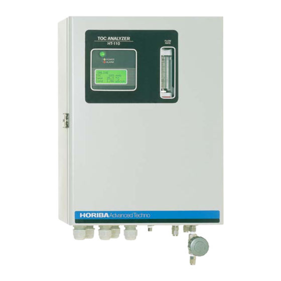
2 System Overview Name of each part Front view Display Flow meter area monitor Bottom view Sample outlet Rc1/4 Calibration solution (8 mm o.d./6 mm i.d.: piping connection) inlet Rc1/8 Wiring opening-in Power opening-in Sample inlet Rc1/8 (6 mm o.d./4 mm i.d.: piping connection) - Page 12 2 System Overview Opening the front door Front panel (Refer to page 5) Terminal board (Refer to page 6)
- Page 13 2 System Overview Front panel POWER switch MAINT switch Power fuse Indication lamp Display area Operation keys CAUTION Do not operate the keys or push the panel surface with a sharp object, such as the fingernail.
- Page 14 2 System Overview Terminal board Alarm contact output TERMINATOR Transmittance output Alarm contact output1, (Refer to page 17) Alarm contact output2 (Refer to page 16) For extension Power L (Refer to page 20) Contact input (Refer to page 19) Note Be sure to use the electrical wire of 0.75 mm to 2 mm (AWG18 to AWG14) for the connection wiring...
-
Page 15: Switches
2 System Overview 2.2.1 Switches Description in this Switch Description document POWER POWER switch Switch to turn ON and OFF the power source. Switch the mode between measurement and maintenance. MAINT ON: Maintenance mode OFF: Measurement mode MAINT switch Reference For each mode, refer to “... -
Page 16: Indication Lamps
2 System Overview 2.2.3 Indication lamps Indication Description Normal measurement state (No error occurred in the measurement mode) Note Measurement, alarm contact output, and transmittance output can be processed even in such messages as UV lamp deterioration or Green lamp lit tube pump deterioration are displayed. -
Page 17: Mode Selection
2 System Overview Mode selection The instrument allows two operation modes and three menus. Operation mode Measurement mode The MAINT switch is “OFF”. This mode allows measurement and control. O N L I N E Online T O C TOC concentration value display p... - Page 18 2 System Overview Maintenance mode (OFFLINE) The MAINT switch is "ON". Press the MENU key to go to OFFLINE state. Measurement and output stop and the Setting Menu is displayed. O F F L I N E S e t M e n u ...
- Page 19 2 System Overview Setting menu The stage under the maintenance mode includes the following menu. For detailed step to enter each menu and parameter, refer to the description in Table 1. System setting (System Set) Measurement condition setting (Meas. Set) Output setting (Output Set) Table 1 Basic setting parameters Display...
-
Page 20: Installation
3 Installation Installation Rating Power supply 100 V to 240 V AC Rated power supply : Frequency: 50/60 Hz Power consumption: 80 VA (MAX) Reference For details, refer to “ 7.1 Specifications ” (page 44). Installation condition This instrument provides splash-proof construction but we assume that it is installed indoor. In order to use it in a stable condition, place it in the following conditions. -
Page 21: Installation Method
3 Installation Installation method For the installation method of this instrument, three types are assumed and mounting brackets are available optionally. Installation to wall surface Use a hole of mounting bracket for installation to the wall surface. At least 155 At least 130 Maintenance space Maintenance space... - Page 22 3 Installation Vertical installation Install to the floor using the hole on the bottom surface as necessary. At least 130 At least 155 Maintenance space Maintenance space 4-φ10 Floor anchor hole [Unit : mm] Note Be sure to refer to the latest drawing as dimensions may sometimes change.
- Page 23 3 Installation Installation example Sample outlet Precautions on piping Outlet 2 Outlet atmospheric release Outlet 1 Outlet 2 Riser Outlet 1 Outlet water seal Drainage pit Sample outlet 2(Rc1/4) (φ8/6 mm pipe) Sample inlet(Rc1/8) Sample outlet1(Rc1/4) (φ6/4 mm pipe) (φ8/6 mm pipe) Regulator Maintenance valve Sample outlet pipe...
-
Page 24: Connection
3 Installation Connection Note Be sure to use the electric wire of 0.75 mm to 2 mm (AWG18 to 14) for wire connection at the terminal board. 3.4.1 Connection of alarm contact output Contact capacity is within 125 V 3 A AC, or within 24 V 3 A DC. When the connected equipment generates noises, use a varistor or a noise killer. -
Page 25: Connection Of Transmittance Output Cable
3 Installation 3.4.2 Connection of transmittance output cable Signal of 4 mA to 20 mA DC, 0 V to 1 V DC (optional) that corresponds to the set measure- ment range is output. The maximum resistance is 600 Ω to convert current to voltage. The input impedance for voltage receiver must be more than 100 kΩ. - Page 26 3 Installation In case of 4 mA to 20 mA DC Receiving instrument OUTPUT (mA) Reception resistance (−) less than 600 Ω Shield When connecting several receiving instruments Connect in series as follows. Resistance of receiving instruments should be less than 600 Ω in total. Receiving instrument 1 OUTPUT (mA) Reception...
-
Page 27: Connection Of The Contact Input Cable
3 Installation 3.4.3 Connection of the contact input cable Connect the cable when measurement with the meter is controlled externally. The input signal should be a contact signal that is maintained continuously for at least one second. CAUTION Input a non-voltage contact signal for the contact. Do not input a signal that has voltage. Connect the cable to the terminal block in accordance with the following diagram. -
Page 28: Power Supply Connection
3 Installation 3.4.4 Power supply connection WARNING Electric shock. Make sure that no electric power is supplied to the instrument before starting this work. Do not turn on the power until your work is completed. Power switch This instrument is equipped with a power switch and fuse (250 V, 3.15 A (T) AC), but for safety, install a circuit breaker (ELCB) with earth leakage breaker function near this instrument. -
Page 29: Attaching Terminal Covers
3 Installation 3.4.5 Attaching terminal covers Put the terminal covers after completion of wiring of the terminal board. WARNING Electric shock Make sure to put the terminal covers to prevent electric shock. Piping configuration Connect the tube joint to the connection on the bottom of the equipment. <... -
Page 30: Measurement
4 Measurement Measurement Preparation Confirm the followings with the power turned OFF. There is no error with power supply, alarm and transmission cable. There is no looseness with the terminal board screws. Supply voltage fluctuation is within the range of rated voltage ±10%. Starting and ending method of measurement When starting the measurement, turn ON the power switch. -
Page 31: Basic Setting
4 Measurement Basic setting When you enter in the maintenance mode, you can perform the settings of the system, measurement condition and outputs. Display item selection (ONLINE) The items displayed on screen can be selected using the ▲ and ▼ keys. 1. -
Page 32: System Setting (System Set Menu)
4 Measurement 4.4.1 System setting (System Set Menu) Setting for when measurement stops (Meas.Set Menu) 1. Refering to " Opening each setting menu" (page 23), display the setting screen of system setting “System Set Menu”. Now the system setting item can be selected with this screen. 2. - Page 33 4 Measurement Warm-up time setting (Warm Up) Set the amount of time that will elapse from the point that measurement is stopped to the beginning of measurement. (This setting also applies to warm-up when the power is turned ON.) 1. Perform the procedures 1. and 2. in " Setting for when measurement stops (Meas.Set Menu)"...
- Page 34 4 Measurement Delay time setting (Delay) Set the amount of time that will elapse between the point of no sample detection and the UV lamp is turned OFF when the "Setting of UV lamp operation" has been set to "Yes". 1.
- Page 35 4 Measurement Setting of UV lamp (UV Lamp Set) Confirming and clearing UV lamp accumulation time (Total) Confirms and clears the accumulation time when the UV lamp is used. To confirm the UV lamp accumulation time 1. Refering to " Opening each setting menu"...
-
Page 36: Measurement Condition Setting (Meas. Set)
4 Measurement 4.4.2 Measurement condition setting (Meas. Set) Selecting the measurement range (Range) Selects your target range. 1. Referring to " Opening each setting menu" (page 23), display the measurement condition setting screen “Meas. Set Menu”. With this screen, measurement condition setting item can be selected. 2. - Page 37 4 Measurement Number of times of temperature moving average (Temp) Set the number of times for the temperature moving average. 1. Perform the procedure 1. and 2. in " Setting the number of times for moving average (M.AVG Set)" (page 28). 2.
- Page 38 4 Measurement Option setting for errors (Err. Option Set) 1. Referring to " Opening each setting menu" (page 23), display the system setting screen “Meas. Set Menu”. With this screen, measurement condition setting item can be selected. 2. Select “Err. Option Set” and press the ENT key. The screen display “Err.
- Page 39 4 Measurement Selecting the sample temperature error (Temp Over) Select between output/not output as an error alarm when the sample water temperature is outside the range of 0.0°C to 99.9°C. 1. Perform the procedures 1. and 2. in " Option setting for errors (Err. Option Set)" (page 30).
-
Page 40: Output Setting (Output Set)
4 Measurement 4.4.3 Output setting (Output Set) Alarm contact output setting (Alarm Set) Set each item for the alarm contact output. 1. Referring to " Opening each setting menu" (page 23), display the output setting screen “Output Set Menu”. With this screen, the output setting item can be selected. 2. - Page 41 4 Measurement Control value (Set) Set the control value as a standard for the point where alarm contact output is turned ON and OFF. 1. Perform the procedure 1. and 2. in " Alarm contact output setting 1 (Alarm1)" (page 32). 2.
- Page 42 4 Measurement Alarm contact output setting 2 (Alarm2) 1. Perform the procedures 1. and 2. in " Option setting for errors (Err. Option Set)" (page 30). 2. Select “Alarm2” and press the ENT key. The screen display “Alarm2 Set Menu” and the alarm contact output setting 2 can be set. The control target for "Alarm contact output setting 2 (Alarm2)"...
-
Page 43: Setting The Input
4 Measurement Transmittance output setting (Analog Set) 1. Referring to " Opening each setting menu" (page 23), display the output setting screen. With this screen, transmittance output setting item can be selected. 2. 「Select “Analog Set” and press the ENT key. The screen displays “Analog Set Menu”... - Page 44 4 Measurement Setting span point (Span) Set the TOC value corresponding the span point output. 1. Perform the procedures 1. and 2. in " Transmittance output setting (Analog Set)" (page 35). 2. Select “Span” and press the ENT key. The display flashes to show now the setting can be performed. 3.
-
Page 45: Troubleshooting
5 Troubleshooting Troubleshooting Troubleshooting Case Cause or Possible Cause Action Power supply voltage is out of Check power supply voltage. rate voltage range Check power supply wiring. The power does not turn Faulty wiring Contact us. Internal abnormality of device Contact us. -
Page 46: Error Code
5 Troubleshooting Error code This device has a function to display various error codes. Error codes are displayed at the bot- tom of the display. 5.3.1 Description and action for error code When error codes are displayed, perform the operation in accordance with the following table. Error code Description Cause or possible cause... -
Page 47: Error Code, Output, And Display Lamp
5 Troubleshooting 5.3.2 Error code, output, and display lamp When error codes are displayed, output and display lamp will be as follows: Error code display Control Alarm contact Transmittance Error code Display lamp Maintenance Maintenance target output output Output error Output error Hold System Error... -
Page 48: Message Code
5 Troubleshooting Error code display Control Alarm contact Transmittance Error code Display lamp Maintenance Maintenance target output output Output error Output error Hold High Pressure Hold Red flash Cond Temp ON : Activates as configured. Output error ON: Activates as output error. (Connected between C-NC) OFF: Alarm contact output behavior stops. -
Page 49: Message Code, Output, And Display Lamp
5 Troubleshooting 5.4.2 Message code, output, and display lamp When message codes are displayed, output and display lamp will be as follows. Message code display Control Alarm contact Transmittance Error code Display lamp target output output Online Offline Output error Output error Hold Warming Up... -
Page 50: Maintenance
6 Maintenance Maintenance UV lamp replacement The lamp needs replacement as its intensity is attenuated with use. Replace the UV lamp immediately when the accumulation time of the UV lamp exceeds 8700 hours, with the sign, "UV Total over" being indicated on the display. WARNING Make sure that POWER switch is turned OFF before replacing the lamp, and that it is cool enough for replacement. -
Page 51: Cleaning
6 Maintenance 8. Replace the O-ring and slowly insert a new UV lamp straight into place. CAUTION Do not touch the glass portion of the UV lamp with bare hands. Wipe any dirt off the surface with alcohol. Connector UV lamp O-ring Fixing bracket Screws... -
Page 52: Reference Materials
7 Reference Materials Reference Materials Specifications Product name Total Organic Carbon Analyzer Model HT-110 Measurement method Continuous UV oxidation conductivity method Measurement limit 0 ppb to 1000 ppb Measurement range 0 ppb to 100/500/1000 ppb Repeatability Within ±2% of full scale 0.1 ppb (0 ppb to 100 ppb / 0 ppb to 500 ppb range) -
Page 53: Parts List
7 Reference Materials Installation Install place: indoor Display function LCD (with a back light) TOC, conductivity, water temperature, alarm Power 100 V to 240 V AC ± 10%, 50/60 Hz built-in fuse 250 V AC 3.15 A (T) Power consumption 80 VA (MAX) Outside dimension 300 (W) mm ×... -
Page 54: Measurement Principle
7 Reference Materials Measurement principle 7.3.1 TOC measurement by continuous UV oxidation and conductivity method Measurement principle The measurement method applies ultraviolet (UV) ray irradiation to flow-type quartz reaction tube, to oxidize organic matter by UV oxidization. From the conductivity variation pre- and post- the reaction tube, the concentration of generated carbon dioxide is calculated under the assumption that organic carbon is to be oxidized into carbon dioxide, and the calculation result is converted into TOC concentration. - Page 55 By calculating the difference in conductivity between the sensor 1 and the sensor 2, TOC can be obtained. Fig. 2 HT-110 internal flow (continuous UV oxidation and conductivity method) Electric conductivity Electric conductivity...
- Page 57 Headquarters 31, Miyanonishi, Kisshoin, Minami-ku, Kyoto, 601-8306 TEL:+81-75-321-7184 FAX:+81-75-321-7291 Tokyo Office Arute Building Higashikanda 4F, 1-7-8, Higashikanda, Chiyoda-ku, Tokyo, 101-0031 TEL:+81-3-3851-3150 FAX:+81-3-3851-3140 Nagoya Office Sumitomo Seimei Chigusa Dai-ni Building 6F 3-15-31, Aoi, Higashi-ku, Nagoya, 461-0004 TEL:+81-52-937-0812 FAX:+81-52-937-0675...
Need help?
Do you have a question about the HT-110 and is the answer not in the manual?
Questions and answers