Table of Contents
Advertisement
Quick Links
Advertisement
Table of Contents

Related Manuals for horiba HR-200


Summary of Contents for horiba HR-200
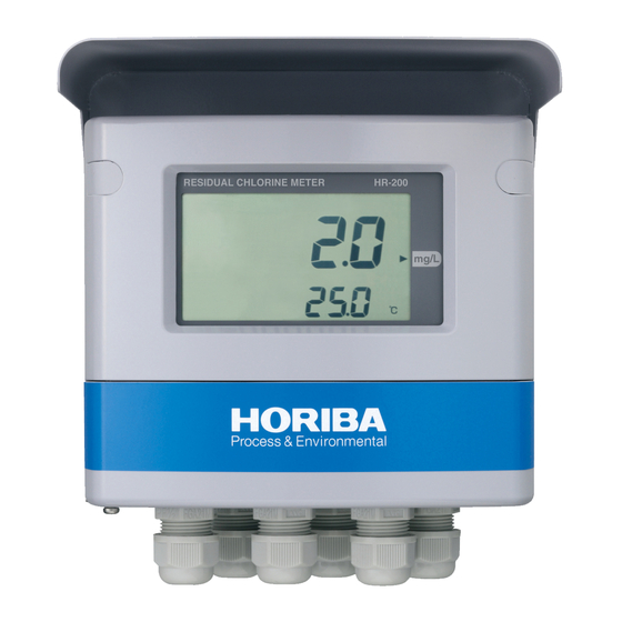
- Page 1 Residual chlorine meter HR-200 Instruction Manual CODE:GZ0000230909G h19136 | UTC 2020/03/30 3:34:51...
- Page 2 HORIBA Advanced Techno, Co., Ltd. warrants that the Product shall be free from defects in material and workmanship and agrees to repair or replace free of charge, at option of HORIBA Advanced Techno, Co., Ltd., any malfunctioned or damaged Product attributable to responsibility of HORIBA Advanced Techno, Co., Ltd.
- Page 3 Regulations Conformable Directive This equipment conforms to the following directives and standards: EMC: EN61326-1 Class A, Industrial electromagnetic environment Safety: EN61010-1 RoHS: EN50581 9. Industrial monitoring and control instruments Warning: This is a Class A product. In a domestic environment this product may cause radio interference in which case the user may be required to take adequate measures.
- Page 4 FCC rules Any changes or modifications not expressly approved by the party responsible for compliance shall void the user's authority to operate the equipment. Warning This equipment has been tested and found to comply with the limits for a Class A digital device, pursuant to part 15 of the FCC Rules.
- Page 5 For Your Safety Hazard classification and warning symbols Warning messages are described in the following manner. Read the messages and follow the instructions carefully. Hazard classification This indicates an imminently hazardous situation which, if not avoided, will result in death or serious injury. This is to be limited to the most extreme situations.
- Page 6 Safety precautions This section provides precautions for using the product safely and correctly and to prevent injury and damage. The terms of DANGER, WARNING, and CAUTION indicate the degree of imminency and hazardous situation. Read the precautions carefully as it contains important safety messages.
- Page 7 Product Handling Information Operational precautions Use of the product in a manner not specified by the manufacturer may impair the protection provided by the product. And it may also reduce product performance. Exercise the following precautions: Do not press any operation key with the tip of your nail or anything pointed. ...
- Page 8 Manual Information Description in this manual Note This interprets the necessary points for correct operation and notifies the important points for handling the product. Reference This indicates the part where to refer for information. This indicates reference information. Term definition This document uses the following terms as defined: Term Definition...
-
Page 9: Table Of Contents
Contents Overview ..........Introduction. - Page 10 Measurement ......... . Measurement mode .
- Page 11 What is residual chlorine? ......... Measuring principle .
- Page 12 h19136 | UTC 2020/03/30 3:34:51...
-
Page 13: Overview
Overview Introduction The HR-200 is designed to measure the concentration of free residual chlorine accurately contained in tap water, swimming pool water, public bath water, or the like. The measuring principle is three-pole polarography method without any treatment by reagents for simple measurement of residual chlorine. -
Page 14: Unpacking
Overview Unpacking Upon delivery of this product, unpack it immediately and check the contents for completeness. In addition, check this product for any damage. If you found any failure, consult a distributor. Breakdown of complete set Converter......1 U bolt.......... 2 ... -
Page 15: Configuration Of Residual Chlorine Meter
Overview Configuration of residual chlorine meter Converter (190) Display Front cover [Unit: mm] Cable gland Sensor RA-10 Overflow cell Sample outlet Measurement cell Sample inlet (258) [Unit: mm] RA-20 Inline cell Sample outlet Measurement cell Sample inlet (258) [Unit: mm] h19136 | UTC 2020/03/30 3:34:51... -
Page 16: Example Of Pole Stand Setup
Overview Example of pole stand setup For RA-10 (HR-200-10P-F-FS10) Converter Sampling valve Flow switch Sensor (RA-10) Sample outlet Sample inlet Filter Maintenance space 700 or more (91) Maintenance space Maintenance space 500 or more 500 or more [Unit: mm]... -
Page 17: Names And Functions Of Each Part
Overview Names and functions of each part Converter Front panel Screw cap Hood Remove a cap to access Hood for outdoor the screw. installation. The measured value and other information is displayed here. Front cover When the cover is opened, there are 6 operation keys. - Page 18 Overview Status display Main display Status display Sub display Indicator Operation keys Terminal block Transmission output terminal RS-485 terminal Sensor connection Flow switch input terminal terminal Contact input terminal Power connection terminal Fuse box Contact output terminal Power switch h19136 | UTC 2020/03/30 3:34:51...
-
Page 19: Sensor
2.0 L/min), the flow rate in the measurement cell can be maintained at a constant level. (4) Converter cable This cable is connected to the converter (HR-200). (5) Measurement cell This cell is used to abrasively clean the sensor surface by shooting out beads while exposing the cathode electrode surface to the sample at a constant flow rate. - Page 20 (15) Mounting bracket This bracket is made of stainless steel, and is used to install the HR-200 on a wall or pole. To install the HR-200 on a pole, purchase the pole stand and pole installation brackets, which are optionally available.
-
Page 21: Operation Section
Overview Operation section Operation keys The operation keys are used to change the displayed information, enter parameters, and perform calibration. When the indication is blinking, the figures and parameters can be changed. Use the arrow keys [/ to select a blinking value or item, and then press ENT. The setting will flash and then be established. -
Page 22: Status Display
Overview Status display Description of display lamps Illuminated in the hold mode (when the transmission output is held). HOLD indicator Starts blinking when contact input is received or when the hold mode becomes active due to an error. CAL indicator Illuminated when the calibration mode becomes active. -
Page 23: Description Of Operation Modes And Menu Items
Overview Description of operation modes and menu items Modes and menus from the measurement mode Refer to page 29. Measurement mode In this mode, measurement and control are performed. [] [] Calibration/Control value setting menu This menu allows you to check the calibrated value or to set/change some controlled values while checking the output. -
Page 24: Installation
Installation Installation Installation environment In order to ensure the stable use of the HR-200, install it in a location that meets the following requirements. Converter The location should be well ventilated. The ambient temperature should be between 20C and 55C. -
Page 25: Installation Method
Installation Installation method Converter The converter is installed on the pole (50 A) or the wall. Spaces for opening the front case are required. Installation on a pole [Unit: mm] Installation on a wall 4-10 11 hole [Unit: mm] h19136 | UTC 2020/03/30 3:34:51... -
Page 26: Installing The Measurement Cell
Installation Installing the measurement cell Wall mount or pole mount whichever is available, the pole mount needs another attachment optionally available. Note Install the measurement cell vertically. The beads cleaning is affected by leaning of the cell, the normal condition for the measurement can not be maintained. -
Page 27: For Installation On The Pole (Optionally Available)
Installation For installation on the pole (optionally available) To install the cell on the pole, the optionally available pole stand and mounting brackets are required. 60.5 (50 A) [Unit: mm] Installing the cell on the pole stand Provide a sufficient maintenance area as shown in the following figure. Maintenance space Maintenance space 500 or more... -
Page 28: Piping Procedure
Installation Piping procedure Piping for sample inlet CAUTION Sample inlet to the flow control valve may be pressurized, careful pipe works are required to ensure safe sealing. Provide a valve to stop and control sample flow. Take sample water from the constant flow line. If the flow rate is variable, select RA-10 ... -
Page 29: Example Of Recommended Piping
Sample outlet: TS socket Nominal 16 For RA-10 (overflow type) pH/ORP option Converter Converter HO-200 HP-200 Converter KCl tank HR-200 Main line Flow switch Filter option option pH electrode electrode Flow rate String wound filter RA-FS10 adjustment RA-F 100 m... - Page 30 Do not return the sampled water for the waterworks or drinking. Converter Regulator Filter option Flowmeter Flow switch HR-200 option option option Main line Flow rate Regulator String wound...
-
Page 31: Wire Connection
1. Remove 2 screw caps located on the front case. Keep them for reuse. 2. Open the front cover. 3. Loosen the 4 screws located on the front case of the HR-200. Check that the screws are pushed up by springs. -
Page 32: Power Supply
Be sure to check that no electric power is supplied before starting the procedure. The HR-200 has a power switch. The power source to the HR-200 is universal rated from 100 V to 240 V AC 10. The terminal screw for the contact output is M4. -
Page 33: Contact Output
If noise is detected from the load, use a varistor or a noise killer. When the HR-200 is normal (without the FAIL output), the C-NOF contact is open and the C-NCF contact short-circuited. When the power is OFF, the C-NOF contact is short- circuited. -
Page 34: Contact Input Terminals And Flow Switch Input Terminals
For the contact input and the flow switch input, use a twisted shielded pair cable. If lightning might strike, install an arrester on the output side of the HR-200 and on the side of receiving instruments. To terminate the cable, strip the covering at the end by 11 mm, and then connect the ... -
Page 35: Connecting The Communication Terminal
Installation Connecting the communication terminal Connecting to the RS-485 terminal The HR-200 has an RS-485 communication terminal. The applicable electric wire is 0.14 mm to 2.5 mm (AWG 26 to AWG 14). For the communication cable, use a twisted shielded pair cable. -
Page 36: Sensor Cable Connection
Shield terminal (black) As shown in the following diagram, connect the sensor cable to the terminal block being careful not to make any mistakes in matching between terminals. HR-200 A: Anode electrode terminal (brown) R: Reference electrode terminal (red) K: Cathode electrode terminal (orange) - Page 37 Extending the sensor cable To lengthen the sensor cable, be sure to use a HORIBA Advanced Techno extension cable (C-7E) and relay box (CT-20CR) exclusively for this purpose. The max. extendable length from the HR-200 to the sensor is 40 m.
-
Page 38: Operation
Operation Operation Preparation for operation When you start using the converter for the first time or resetting it to factory settings, be sure to complete the following preparation procedures. Check of converter and detector installation condition (refer to “ Installation method ” ... - Page 39 Operation Setting Initial Refer Display Item Description range setting to page Specify the item to be displayed when r1, r2, t, powered or returned to the measurement 1 mode. S.diSP Sub display setting Note: Indication varies according to choice of 2 t, r1, r2 “Temperature display setting for sub display”...
- Page 40 Operation Setting Initial Refer Display Item Description range setting to page Transmission output hold Specify the transmission output value when HoLd, C.HoLd (current hold) setting for HoLd transmission output 1 is in the hold mode. PrES transmission output 1 Transmission output 1 hold 0.00 to 3.00 PrES...
-
Page 41: Measurement
Measurement Measurement Measurement mode Operation 1. Turn the power ON. The measurement object is displayed on the main display. A measurement range is also displayed with the measurement mode selected. Measurement starts with the measured value displayed. In the measurement mode, this is the normal state. Turn ON the power. - Page 42 Measurement Measurement mode Contact output check setup screen (Example with r1 and “AL” selected) Controlled value Delay time setup screen setup screen Establishes the value Setting change Cancels the value Cleaning check screen Cleaning Wait Cleaning operation Time screen check screen Calibration data check screen Displays the elapsed Display of zero...
- Page 43 Measurement Display Display condition Item Description Setting range Relay setting condition screen (the numeral at the lower left indicates the relay number) When “CtrL”, “AL”, or “t” is : 0.00 to Displays the set value (residual selected. 3.00 (mg/L) Control value setting chlorine concentration or Temperature:...
- Page 44 Measurement Display Display condition Item Description Setting range Displays the zero point deviation of a Zero value check sensor using the residual chlorine screen concentration (mg/L). With calibration Displays the number of days elapsed data Screen for displaying since the last calibration. the number of days Note: elapsed since the last...
-
Page 45: Setup Menu
Measurement Setup menu The setup menu allows you to set the measurement conditions, display method, calibration method, and transmission output. Entering the setup menu 1. Hold down HOLD in the measurement mode until the HOLD indicator turns ON. 2. Use the arrow keys [/] and select “SEt” for the set up menu. 3. - Page 46 Measurement Setting Display Item Description range This setting returns the system from the hold mode to the measurement mode automatically. yES: The mode is automatically returned when the specified Auto return setting yES, no time has elapsed since the last key operation. no: As the mode is not automatically returned, it is necessary ...
- Page 47 Measurement Setting Display Item Description range Contact output setting: R1 to R2 For the settings of relay 2, the numeral for relay 1 is replaced with 2, respectively. Reference For the options available for the selected control target, refer to “ Control targets and their available options ”...
- Page 48 Measurement Setting Display Item Description range Setting temperature Specify the temperature error (E-21 to E-25) is output from the yES, no error for FAIL FAIL contact or not. Setting no-flow error Specify the no-flow error (E-61) is output from the FAIL contact yES, no for FAIL or not.
- Page 49 Measurement Setting Display Item Description range Specify the transmission output value when transmission output Transmission output 2 is in the hold mode. hold (current hold) HoLd, setting for PrES HoLd: Holds and outputs the latest value transmission output 2 PrES: Outputs the preset value ...
- Page 50 Measurement Contact output Control targets and their available options Make the setting referring to the table shown below. Displayed options vary depending on the settings shown in gray. Items with a check mark are available for selection. Table 4 Control targets and their available options Description Function assignment of contact Specifies a contact...
- Page 51 Measurement Contact output types The following contact output types are available. non: No output. This setting disables the contact output. CtrL: Control output. When the measured value is higher than the point [control value + control width 1/2], the control output turns off to stop injection.
- Page 52 Measurement Example of “Hi” alarm output 3.00 Control value Measured value 0.00 Contact output (r1 to r2) Delay time t: Temperature alarm output. When the temperature value is higher than the setting, the output turns ON following the delay time, triggering the alarm. When the temperature value becomes lower than the setting, the output is immediately turned OFF to cancel the alarm (The above explanation is applicable to the upper limit operation.
- Page 53 Measurement Contact output reactions in each condition Contact output reactions in each condition is shown below: FAIL output Transmission output Diagnos Measure ed error d value Abnormal Contact Transmission Transmission by self- out of full temperature flowing Status Output output 1 output 2 check...
- Page 54 Measurement FAIL output Transmission output Diagnos Measure ed error d value Abnormal Contact Transmission Transmission by self- out of full temperature flowing Status Output output 1 output 2 check scale “F.tE” “F.FLo” r1 to r2 “F.SC” “F.oF” Without With Without With yES no yES no burnout...
-
Page 55: Calibration Menu
Measurement Calibration menu Entering the calibration menu allows you to calibrate the residual chlorine sensor and the temperature sensor. Entering the calibration menu There are two different procedures available for entering the calibration mode. This section describes the procedure for entering calibration menu from the hold mode. Operation 1. - Page 56 Measurement Table 5 List of items displayed for the calibration menu Calibration Setting Display Item Description Type range Zero liquid calibration Reference For zero liquid calibration procedure, referring to “ Calibration by zero solution ” (page 58). Manually perform the zero calibration. Zero Screen displayed Send the zero water to the sensor, and wait...
-
Page 57: User Check Menu
Measurement User check menu Entering the user check menu allows you to view the display and transmission output and to initialize the settings. Entering the user check menu 1. Hold down HOLD in the measurement mode until the HOLD indicator turns ON. 2. - Page 58 Measurement Display Item Description This screen allows you to check that FAIL contact turns ON/OFF. Screen to check FAIL ENT: Alternates ON and OFF. output Note: When this mode becomes active, the contact output turns OFF. Check the transmission output 4 mA is output to transmission output 1 and 2.
-
Page 59: Maintenance
Maintenance Maintenance This chapter provides information on maintenance in order to ensure the highest accuracy and optimum use of the HR-200. List of periodic checks This section describes the general check items for the residual chlorine sensor. Periodic checks followed are necessary for accurate measurement. -
Page 60: Maintenance Of Sensor
Maintenance Maintenance of sensor This section describes the maintenance procedure for a general residual chlorine sensor. Checking the flow rate of the sample For the residual chlorine sensor, measured data is affected by the sample flow rate. If the flow rate decreases due to clogged piping or the like, the reading may become lower. -
Page 61: Check Of Residual Chlorine Concentration
Maintenance Check of residual chlorine concentration This instrument measures residual chlorine without sample conditioning by reagent. The pH or conductivity will affect measurement data. Check the residual chlorine of the sample water by a DPD method tester for getting a reference concentration. Once a day is recommended. Perform calibration whenever water quality is changed or after maintenance of the detector (cleaning of the electrode or the cell, replacement of the electrode or beads) with a sampling valve closed. - Page 62 Maintenance 4. Remove the cathode electrode from the sensor holder. Cathode electrode Note The surface of the gold cathode should be clean and smooth. Reading will be affected by the residual contamination on the cathode surface. 5. Clean up contamination on the cathode electrode surface. Wipe off any remaining foreign matter on the cathode electrode with soft cloth or the ...
-
Page 63: Replacing The Cleaning Beads/Cleaning And Or Replacement Of The Mesh Filter
Maintenance Replacing the cleaning beads/Cleaning and or replacement of the mesh filter Suggestion of the bead choice Two types of cleaning beads are attached within the sensor unit. Normally glass beads are used for cleaning. If the metal coating on the cathode surface is insistent, ceramic beads are recommended. - Page 64 Maintenance 4. Discard the old cleaning beads, and replace with new cleaning beads. 5. Install the beads cell by reversing the steps for removing it. Note Wipe the beads if remained around the O-ring before attaching beads cell on the measurement cell. Beads around the O-ring will disturb sealing.
-
Page 65: Replacing The Sensor (Cathode Electrode)
Maintenance 2. Remove the O-ring attached to the measurement cell nozzle, and then take out the mesh filter. Clean or replace the filter depending on how contaminated it is. Insert the Mesh filter rounded net into the hole. Round the net (mesh filter). Filter supporter O-ring 3. -
Page 66: Cleaning Of Measurement Cell
Maintenance 4. Remove the cathode electrode from the sensor holder. Cathode electrode Note The surface of the gold cathode should be clean and smooth. Reading will be affected by the residual contamination on the cathode surface. 5. Supply a new cathode electrode and attach it to the sensor holder. 6. -
Page 67: Cleaning The Overflow Cell (Ra-10)
Maintenance Cleaning the overflow cell (RA-10) Water stains or the like that adhere to the overflow cell over time eventually flake off and flow into the measurement cell, causing the mesh filter to be clogged. Operation 1. Turn OFF the converter. 2. -
Page 68: Pausing The Analyzer
Maintenance Pausing the analyzer When sample is stopped be sure to turn off the power because the cathode electrode will be plated by silver. If the cathode is plated by silver, the measurement data will be reduced. Operation 1. Turn OFF the converter. 2. -
Page 69: Calibration
Maintenance Calibration The calibration is classified into the zero calibration, the span calibration, and the temperature calibration. Before calibration wait a few minutes for warm up Do not calibrate the sensor immediately after powered, wait to warm up and confirm that the reading is stable. - Page 70 Maintenance Calibration by zero solution The zero point is adjusted to the reading of the flowing zero solution for the strict calibration. Zero solution should be non-chlorine water. Operation 1. Enter the calibration mode by performing the operation described in “ Calibration ” (page 57), and then step into the Zero calibration screen.
- Page 71 Maintenance Span calibration In the span calibration, the electrical zero calibration is carried out automatically. Span calibration needs a reference value of concentration by a DPD tester. Operation 1. Check the residual chlorine concentration of the sample water with a DPD analysis. 2.
- Page 72 Maintenance Temperature calibration It is not necessary to calibrate temperature daily. Operate this mode once if you mind or if the temperature error exceeds 0.2C. Confirm that the temperature reading on the converter is stable. Measure the temperature of the sample water with a reference thermometer. When the hold mode is selected, the transmission output becomes the value specified on the setup menu.
-
Page 73: Troubleshooting
Sudden change of Avoid sudden temperature change of sample water. temperature Install the HR-200 in an environment where the pH value does not The residual chlorine data change significantly. of the HR-200 is affected by pH of the sample water. -
Page 74: Measurements Exceeding The Measurable Range
Troubleshooting Symptom Possible cause Remedial action Unexpected short circuit or open circuit in the sensor Check the sensor cable. An abnormal cable. value is displayed. Loosened terminal Check the terminal block. connection Unexpected The circuit board is Supply clean instrumentation air from the air purge inlet. operation corroded by corrosive gas. -
Page 75: Error Codes
Troubleshooting Error codes The HR-200 announces an error code blinking on the sub display. Description of error codes Priority Display level of Error Description Occasion 1 error The sensor current is low during the span E-12 Span calibration error calibration. -
Page 76: Remedial Actions For Error Codes
Troubleshooting Remedial actions for error codes When an error code is displayed, take remedial action in accordance with the table below. Error code Triggering condition Reset condition Possible cause Remedial action Deterioration of the The signal from the sensor. - Page 77 The power is (System error) malfunction again. turned ON/ Internal system error If the system error appears The stored data, such OFF. again after the HR-200 is E-92 as settings and restarted, contact us. (System error) calibration values, is volatilized. h19136 | UTC 2020/03/30 3:34:51...
-
Page 78: Data
Data Data Specifications Converter Product name Residual chlorine meter Model HR-200 Combined sensor RA-10 or RA-20 (3-pole polarographic method sensor) Residual chlorine 0.00 mg/L to 3.00 mg/L (display range: 0.00 mg/L to 5.00 mg/L) Measurement concentration range 0C to 50C (display range: 10C to 110C) - Page 79 Data Number of input Contact type No-voltage “a” contact for open collector ON resistance: 100 max. Contact input Conditions Open voltage: 24 V DC Short-circuit current: 12 mA DC max. Input 1: External input for transmission holding Contact function Input 2: Flow switch input for interlock (open: decreased flow).
- Page 80 Data Structure Outdoor installation Installation method Mounted on 50 A pole or wall Protection code IP65 Case material Aluminum alloy (coated with epoxy-denatured melamine resin) Structure Material of fittings SUS304 Material of hood SUS304 (coated with epoxy-denatured melamine resin) Material of window Polycarbonate Display element Reflective monochrome LCD...
-
Page 81: Sensor
Sample flow must be kept constant. The sensor is affected by flow rate. 3: If the regulator recommended by HORIBA Advanced Techno is used inlet pressure should be over 0.1 MPa. 4: Sample pH should be constant. This sensor is dependent on the pH which effects the dissociation of hypochlorous acid. -
Page 82: Cathode Electrode
Data 6: The sample outlet of the RA-10 must be atmospheric pressure. Shorter piping is recommended to reduce back pressure. 7: The concentration of metallic ion in the sample should be less than standard value of Water Supply Act in Japan. 8: If the sensor is exposed to direct sunlight, the electrode may deteriorate. -
Page 83: Flow Switch
Data Flow switch Product name Flow switch for Residual chlorine meter (model: RA-10) Model RA-FS10 Setup flow 1.2 L/min contact open due to decreased flow Wetted materials PVC, EPDM, PPO Operating temperature 0C to 50C (without freeze) Pressure 0 MPa to 0.5 MPa Direction Horizontal Switch case must be kept upward. -
Page 84: Integrated Rack
Data Integrated rack Product name Integrated rack Temperature 0C to 45C (without freeze) Y: 1.2 to 2.0 L/min RA-10 Flow switch RA-FS10 N: 1.3 to 2.0 L/min Flow rate Y: 0.8 L/min RA-20 Flow switch RA-FS20 Sample condition N: 0.8 L/min Y: 0.02 to 0.75 MPa Pressure Regulator... -
Page 85: Technical Data
Data Technical data What is residual chlorine? Residual chlorine means hypochlorous acid that is produced when chlorine agent is dissolved in water and chloroamine that is produced when hypochlorous acid is combined with ammonia. The former is called free residual chlorine and the latter combined residual chlorine. The two are collectively called residual chlorine. -
Page 86: Measuring Principle
Data Measuring principle The measuring principle of the HR-200 is three-pole polarographic method. Gold is a material of the cathode electrode, silver is used for the anode electrode and silver/silver chloride is used for the reference electrode. The reference electrode regulates the potential to be constant between the sample and cathode electrode (Fig. -
Page 87: Conditions For Sample
Effect of electrical conductivity of sample Electro chemical reaction is needed to measure residual chlorine for the HR-200. The sensitivity is affected by the conductivity less than a specified level (Fig. 4). Add electrolyte for example sodium chloride to keep the conductivity more than 100 S/cm for low conductive sample. - Page 88 Correct reading is achieved on the assumption of the constant and proper flow rate. Effect of sample temperature In the polarographic method used by the HR-200, the signal from the sensor is affected by the temperature of the sample. There are two main reasons of the temperature dependency.
-
Page 89: Electrochemical Cleaning Capability
After replacing the sensor, warm up (for break-in) for at least 3 h and then start the calibration. Electrochemical cleaning capability The HR-200 uses an electrochemical reaction to measure the concentration of residual chlorine. General tap water, swimming pool water, and bath water contain metallic ions. When metallic ions reach the surface of the cathode electrode, metallic ions receive electrons and will be reduced to metal which is plating on the cathode surface. -
Page 90: Parts List
Data Parts list Optionally available parts Model Part name Specification Part No. PS-50 Pole stand 50 A 1500 mm 3030047360 1 100 m Mesh filter 3200303108 RA-F 2 Flow switch For RA-10 3200313530 RA-FS10 2 Flow switch For RA-20 3200315158 RA-FS20 2... -
Page 91: Disposing Of The Instrument
Dispose of this product in accordance with local laws, ordinances and regulations. Parts of this product are made of the following materials. The parts for the HR-200 are made of the following materials. Converter 4-Pan screw M5 10 6-Pan screw M3 ... - Page 92 Data Name Material Name Material Glass Spacer C3604BD LCD packing PCB (H4W-ANL-0x) LCD holder ADC12 PTFE plate PTFE Case packing Protective sheet U Plunger packing R Upper hinge ADC12 Parallel pin SUS304 Screw cap 2 Terminal ID plate RC Functional ground information plate PET Terminal block information plate FG mesh Terminal cover 4U...
-
Page 93: Overflow Integrated Sensor
Data Overflow integrated sensor 23 24 Name Material Name Material Thumbscrew SUS304 O-ring (S80) EPDM Beads cell 2 Rating plate B1 O-ring (S30) Case paint 3 ADC12 Measurement cell Cable gland 66 Nylon + EPDM Cell support L SUS304 Sensor cap O-ring (S50) Sensor holder... -
Page 94: Inline Sensor
Data Inline sensor 15 16 17 18 19 20 Name Material Name Material Thumbscrew SUS304 Case paint 3 ADC12 Beads cell 2 Cable gland 66 Nylon + EPDM O-ring (S30) Sensor cap Measurement cell Sensor holder Cell support L SUS304 Cathode tip (RA-K) Au + PPO + FKM... -
Page 95: Quick Reference
Data Quick reference (appendix) Quick reference is a digest of the instruction manual. h19136 | UTC 2020/03/30 3:34:51... - Page 96 Residual chlorine monitor HR-200 Operation procedure 1 Names of display panel Residual chlorine concentration calibration Temperature calibration Indicator lamps Status display lamps Calibration by zero solution Span calibration Turns ON while a contact signal Cal mode (CAL) is being input externally.
- Page 97 h19136 | UTC 2020/03/30 3:34:51...
- Page 98 Residual chlorine monitor HR-200 Operation procedure 3 (Change the setting and mode) How to operate the hold mode from the maintenance mode. Hold down [HOLD] until the HOLD lamp lights up. “SEt” will be displayed on the main display and measured stops.
- Page 99 Residual chlorine monitor HR-200 Operation procedure 4 (Change the setting and mode) Setting self checked sensor error for FAIL Transmission output 2 value (zero range) setting Setting range: 10.0 to 110.0 (C) Setting range: yES, no Initial setting: no Initial setting: 0.0 (C)
- Page 100 h19136 | UTC 2020/03/30 3:34:51...
- Page 101 h19136 | UTC 2020/03/30 3:34:51...
- Page 102 h19136 | UTC 2020/03/30 3:34:51...
- Page 103 Headquarters 31, Miyanonishi-cho, Kisshoin Minami-ku, Kyoto, 601-8306 Japan TEL:+81-75-321-7184 FAX:+81-75-321-7291 h19136 | UTC 2020/03/30 3:34:51...
Need help?
Do you have a question about the HR-200 and is the answer not in the manual?
Questions and answers