Table of Contents
Advertisement
Quick Links
Advertisement
Table of Contents

Related Manuals for horiba HU-200TB-W SS-120-W


Summary of Contents for horiba HU-200TB-W SS-120-W
- Page 1 Turbidity meter HU-200TB-W SS-120-W Instruction Manual CODE:GZ0000361148F...
- Page 2 HORIBA Advanced Techno, Co., Ltd. warrants that the Product shall be free from defects in material and workmanship and agrees to repair or replace free of charge, at option of HORIBA Advanced Techno, Co., Ltd., any malfunctioned or damaged Product attributable to responsibility of HORIBA Advanced Techno, Co., Ltd.
- Page 3 Regulations Conformable Directive This equipment conforms to the following directives and standards: EMC: EN61326-1 Class A, Industrial electromagnetic environment Safety: EN61010-1 RoHS: EN50581 9. Industrial monitoring and control instruments Warning: This is a Class A product. In a domestic environment this product may cause radio interference in which case the user may be required to take adequate measures.
- Page 4 FCC rules Any changes or modifications not expressly approved by the party responsible for compliance shall void the user's authority to operate the equipment. Warning This equipment has been tested and found to comply with the limits for a Class A digital device, pursuant to part 15 of the FCC Rules.
- Page 5 For Your Safety Hazard classification and warning symbols Warning messages are described in the following manner. Read the messages and follow the instructions carefully. Hazard classification This indicates an imminently hazardous situation which, if not avoided, will result in death or serious injury. This is to be limited to the most extreme situations.
- Page 6 Safety precautions This section provides precautions for using the product safely and correctly and to prevent injury and damage. The terms of DANGER, WARNING, and CAUTION indicate the degree of imminency and hazardous situation. Read the precautions carefully as it contains important safety messages.
- Page 7 Product Handling Information Operational precautions Use of the product in a manner not specified by the manufacturer may impair the protection provided by the product. And it may also reduce product performance. Exercise the following precautions: Do not press any operation key with the tip of your nail or anything pointed. ...
- Page 8 Manual Information Description in this manual Note This interprets the necessary points for correct operation and notifies the important points for handling the product. Reference This indicates the part where to refer for information. This indicates reference information. Term definition This document uses the following terms as defined: Term Definition...
-
Page 9: Table Of Contents
Contents Overview ..........Introduction. - Page 10 Preparation for operation ........Initial setup ........... . Measurement .
- Page 11 Preparation method of calibration solution ......Formazin 4000 NTU..........Kaolin standard solution.
-
Page 13: Overview
Overview Overview Introduction This product consists of a converter (HU-200TB-W) and a flow through type turbidity detector (SS-120-W). This instrument measures the low and high range turbidity accurately with a right angle scattering/transmission method. Any measured values are displayed to the second decimal place. -
Page 14: Features
Overview Features Converter Aluminum die cast Wide wiring space and a terminal block provided with a screw drop-off prevention function Outdoor installation type (equivalent to IP65; splash-proof construction) Easy to view display (150 zoom as compared with our conventional type) ... -
Page 15: Unpacking
Overview Unpacking Upon delivery of this product, unpack it immediately and check the contents for completeness. In addition, check this product for any damage at the same time. Breakdown of complete set Converter Main body....1 U bolt.......... 2 ... -
Page 16: Names And Functions Of Each Part
Overview Names and functions of each part Converter Front panel Cover This cover is used for Screw cap outdoor installation. When the two screw caps are removed, the front case screws appear. Display section The measured value and other information are dis- played here. - Page 17 Overview Display section Status display Main display mg/L (Kaolin: Unit of SS concentration) TURB (Turbidity: Unit of degree) Status display NTU (Formazin) Indicator KAOLIN (Kaolin) PSL (Polystyrene Latex) Sub display Operation key section Terminal block ...
-
Page 18: Detector
Overview Detector Diagram showing the automatic cleaner attached Cleaner cover Sample outlet Cleaner locking screw Desiccant holder Detector connector Sample inlet Cleaner connector Automatic cleaner cable Diagram showing the automatic cleaner detached U bolt 2 sets O-ring Right cover Left cover Window cover... - Page 19 Overview Option Automatic cleaner Cleaner cover Knurled screw Pressure releasing hole Shaft Wiper Wiper holder Wiper support Liquid span bottle Calibration jig Calibration bottle Seal the calibration bottle with a liquid solution of Kaolin that has been properly adjusted according to the measurement range.
-
Page 20: Operation Section
Overview Operation section Operation keys Operation keys are used to switch displays, enter settings, and perform calibration, etc. You can change the value or item while the display is blinking. Select a value or item with /, and press ENT. The display will flash, and the setting will be finished. -
Page 21: Status Display
Overview Status display Description of display lamps This indicator is illuminated while the hold mode is active. HOLD indicator Starts blinking when contact input is received or when the hold mode becomes active due to an error. CAL indicator Turns ON when the Cal mode becomes active. -
Page 22: Description Of Operation Modes And Menu Items
Overview Description of operation modes and menu items Modes and menus from the meas mode Meas mode The sample water is measured and transmission signals and relays are con- trolled. Press Press Press / Contact output check setup screen (display example when r1 is set) This menu allows you to check the calibrated value or to set/change some controlled Refer to page 35 . -
Page 23: Installation
Installation Installation Installation environment To keep the HU-200TB-W stable and reliable for use, install it in a place where the following conditions are satisfied. Converter Well-ventilated location. Ambient temperature in the range of 20C to 55C. Not exposed to direct sunlight. ... -
Page 24: Installation Method
Installation Installation method Installing the converter The HU-200TB-W can be installed on a pole (50 A) or a wall. Spaces for opening the front case are required. Installation on a pole [Unit: mm] Installation on a wall Slotted hole of 4-10 ... -
Page 25: Installing The Detector
Installation Installing the detector Use the supplied U-bolt to attach the detector to the pole (50 A). This work can be performed easily when the detector is installed at a height of 1 m. Attach a stand (option) to the upper section of the same piping used for holding the ... -
Page 26: Piping
Installation Piping Flow Piping from 15 A to 20 A is suitable for the detector. If the turbidity and flow rate are low, 8 mm/6 mm black nylon tube can be used. For the detector, be sure to run sample water upward from the bottom. - Page 27 Installation In-line (automatic zero calibration) Overflow tank (manual zero calibration) Overflow tank (automatic zero calibration) ...
-
Page 28: Sampling
Installation Sampling sampling pump Types of sampling pump For a sampling pump, select a submerged centrifugal pump that is free from rusting. Some types of pump, such as cascade-type pumps, diaphragm-type pumps, piston pumps, tube pumps, and gear pumps, are not suitable for use because the discharge pressure rises rapidly when the pump outlet is closed. - Page 29 Installation Influence of soiled piping If a low flow rate is set, solids may flake off from the soiled sampling piping due to the fluctuations in the flow rate or vibration of the piping. This may eventually influence the turbidity.
-
Page 30: Wire Connection
Installation Wire connection Opening the cover for the converter 1. Remove the two screw caps located on the top on the front of the converter. Carefully store the removed caps. 2. Open the front cover. 3. Loosen the four screws located on the front of the converter. Check that these screws are pushed forward by the spring force without falling off. -
Page 31: Power Supply
Installation Power supply WARNING If there is a possibility of a lightning strike, install an arrester on the output side and receiving instrument side of the converter. Electric shock hazard Be sure to check that no electric power is supplied before starting the procedure. A power switch is equipped beside the terminal block. -
Page 32: Contact Output R1 To R3
Installation Contact output R1 to R3 The terminal screw for the contact output are M4 type. The applicable electric wire is of 0.75 mm to 5.5 mm (AWG18 to AWG10). For wire connection, remove the black resin terminal cover for the power terminal by ... -
Page 33: Failure Output
Installation Failure output WARNING To connect any load exceeding the contact capacity or any induction load (e.g., motor, pump), be sure to use a power relay. If you want a break signal for power OFF or abnormality, use the contact with CF and NCF. When this equipment is normal (not malfunctioning), the CF-NOF contact is opened, and the CF-NCF contact is short-circuited. -
Page 34: Range Output
Installation Range output For transmission output 2, a maximum of four measurement ranges can be switched externally or automatically. The range currently output for transmission output 2 can be recognized at the range output contact. An arbitrary range, from range 1 to range 4, can be set for transmission output 2 (zero and span values). -
Page 35: Control Output For Automatic Zero Calibration (Ac Power-Supply Voltage Output)
Installation Control output for automatic zero calibration (AC power-supply voltage output) This is a voltage control output that controls the electric ball valve for the sample water line and solenoid valve for zero water. For the sample water line, in order to control the electric ball valve applicable to a large bore size, power is supplied to either the open or close operation. -
Page 36: Connecting The Transmission Output Terminals
Installation Connecting the transmission output terminals WARNING If there is a possibility of a lightning strike, install an arrester on the output side and receiving instrument side of the converter. The terminal screws for transmission output are of the M3.5 type. ... -
Page 37: Connecting The Contact Input Terminal
Installation Connecting the contact input terminal The applicable electric wire is of 0.14 mm to 2.5 mm (AWG26 to AWG14). For the cable for contact input, use a twist pair shielded wire. If lightning might strike, install an arrester along the signal line. ... - Page 38 Installation RS-485 Connecting the RS-485 terminal Two wire communication RS-485 is ready to use for sending data to host computer. The applicable electric wire is of 0.14 mm to 2.5 mm (AWG26 to AWG14). For the communication output cable, use a twisted shielded pair. ...
-
Page 39: Sensor Cable Connection
Installation Sensor cable connection Cautions for the sensor cable connection Turn OFF the power during the connection work. Connections Connect the sensor cables correctly to the corresponding terminals on the terminal block, according to the illustration below. The sensor cable has the following terminals: 12 V 1: Power supply... -
Page 40: Operation
Operation Operation Preparation for operation When you start using the converter for the first time after factory shipment or resetting it to factory settings, be sure to complete the following preparation procedures. Check of converter and detector installation condition (refer to “ Installation method ” ... - Page 41 Operation Setting Initial Refer Display Item Description range value to page SEnSor Sensor setting Select the turbidity standard substance from Turbidity standard SiO, For, tyPE among Kaolin (SiO), Formazin (For), and substance (type) selection Polystyrene Latex (PSL). For Kaolin, turbidity or mg/L can be further selected for the unit of measurement.
- Page 42 Operation Setting Initial Refer Display Item Description range value to page Contact output setting: R1 to R3 The other relays can be set in the same manner. r1 to r3 Reference Refer to “ Control targets and their available options ” (page 48) for the options available for the selected control target.
- Page 43 Operation Setting Initial Refer Display Item Description range value to page FAiL output delay time Specify the time in seconds from when a FAiL F.dt 0 to 600 (s) setting occurs until a contact is output. Curr General transmission output setting Transmission hold plan in Specify the transmission holding status in C.HoLd...
- Page 44 Operation Setting Initial Refer Display Item Description range value to page Specify the value at the zero point Cur2.A (4 mA) of transmission output 2.A. Cur2.b/2.c 0.00 to Note: Zero point value setting for 11.00, 0.0 to rng.0 The item of sub display depends transmission output 2.A 110.0, 0 to on which ever “10.00”...
- Page 45 Operation Setting Initial Refer Display Item Description range value to page Ein1 External input 1 (calibration/hold) When external input 1 is a calibration command (“Setting of automatic zero calibration start method” is set to “or”, “And”, or “trg”), if this contact is closed, zero calibration and its associated operations will be started automatically.
-
Page 46: Measurement
Measurement Measurement Measurement mode 1. Turn the power ON. The measurement target appears on the main display and the measurement range is displayed. After the measurement range is displayed, the measurement starts. This is the normal measurement mode. Power ON Displayed for Detector connection Meas mode... - Page 47 Measurement List of items displayed in the meas mode Display Displays Item Description Setting range condition Displays the measured values, unit of measurement, and Main display screen type of turbidity standard substance. Contact output check setup screen (display example when r1 is set) The other relays can be set in the same manner.
- Page 48 Measurement Display Displays Item Description Setting range condition When “CAL” is set in “1.tyPE” Screen for issues an When “CAL” is output in a hold set in “1.CAL.t” state during and after zero calibration Screen for outputs the contact for 5 When “trg”...
- Page 49 Measurement Display Displays Item Description Setting range condition Calibration data check screen Calibration data check screen Displays the ratio () of the factory- configured amount of transmitted light during zero calibration to the amount of Screen for checking transmitted light during the latest zero the light intensity for calibration.
-
Page 50: Setup Menu
Measurement Setup menu The setup menu allows you to set any parameters, select turbidity standard substances for the detector and units of measurement, and to specify any display, transmission output, relays and communication addresses. Entering the setup menu 1. In the meas mode, hold down HOLD until the HOLD indicator turns ON. 2. - Page 51 Measurement List of items displayed for the setting menu Setting Display Item Description range Parameter setting Moving Increase dF to reduce variations in the measured data: average count 1 to 120 Decrease dF to speed up the response. (damping (times) It is possible to change the damping factor in the meas mode.
- Page 52 Measurement Setting Display Item Description range Display setting Select either the fixed decimal point or automatic decimal point shift. Auto: Position of the decimal point is automatically changed according Selection of Auto, to the turbidity value. automatic 10.00, Fixed decimal point: Select the optimal position of the decimal point ...
- Page 53 Measurement Setting Display Item Description range Automatic zero calibration setting Select “yES” when an external electric ball valve and a solenoid valve for Automatic zero automatic zero calibration are installed. calibration yES, no Set to “no” when the automatic zero calibration function is not available or setting to stop the function.
- Page 54 Measurement Setting Display Item Description range Contact output setting: R1 to R3 The other relays can be set in the same manner. Reference Refer to “ Control targets and their available options ” (page 48) for the options available for the selected control target.
- Page 55 Measurement Setting Display Item Description range Specify the calibration contact type. CAL: Issues an output in a hold state during and after zero calibration trg: Outputs the contact for 5 seconds starting 2 seconds after the Output type completion of calibration CAL, trg, setting for...
- Page 56 Measurement Setting Display Item Description range Specify the burnout current of the transmission output when an error occurs during measurement. Burnout hold out.4: Outputs 3.8 mA at the time of burnout setting for non, general out.4, out.20: Outputs 21 mA at the time of burnout ...
- Page 57 Measurement Setting Display Item Description range Specify the value at the zero point (4 mA) of transmission output 2.A. 0.00 to Zero point Any value within the range can be set. 11.00 value setting 0.0 to Note: 110.0 transmission The item of sub display depends on which ever “10.00” , “100.0”...
- Page 58 Measurement Setting Display Item Description range Specify the way to start cleaning with a internal timer or a combination of external command. nor: Cleaning will start in accordance with the internal timer setting. The external command can be used to hold the transmission output. or: Cleaning is performed in accordance with the internal timer or ...
- Page 59 Measurement Setting Display Item Description range External input 2 (cleaning/hold) When external input 2 is a cleaning command (“tyPE” of Cleaning operation setting is set to “or”, “And”, or “trg”), if this contact is closed, automatic cleaning and its associated operations will be started. Selection of command by Note:...
- Page 60 Measurement Contact output Control targets and their available options Assign the contact output type which means task of the relay R1, R2 and R3 and set the following items. The available items depend on the relay assignment are grayed. The items marked with a check are available for display as options.
- Page 61 Measurement Contact output types The following contact output types are available. non: No output This setting disables the contact output. Concentration alarm output When a measured value is continuously higher than the set value for triggering an alarm during the specified delay time, the contact is output after the delay time (turning ON a relay) and an alarm occurs.
- Page 62 Measurement Output conditions for each output type The output conditions for various output types are shown below. Contact output Transmission output C.HoLd (Operation Status bet. HoLd PrES non AL HoLd CF-NCF) b.out FAIL output setting Power OFF Opened (ON) When normal operation Closed (OFF) Measurement value...
- Page 63 Measurement Cleaning start condition The automatic cleaning is performed according to the following conditions. Cleaning operation conditions Cleaning and associated operations Internal HoLd External Cleaning cleaning cycle Contact Contact contact input operation Transmission Cleaning start type During output output ON: ...
- Page 64 Measurement Calibration start condition The automatic zero calibration is performed according to the following conditions. Automatic zero calibration operation conditions Calibration and associated operations Calibration HoLd External Calibration cycle Contact Contact contact input operation Transmission CAL Calibration start type During output output...
-
Page 65: Cal Menu
Measurement Cal menu Calibration menu allows you to perform zero and span calibration of the detector. As a rule of thumb, zero calibration and span calibration should be performed once a month. Entering the cal menu Calibration menu can be opened by pressing down CAL in the measurement mode or selected in the hold mode. - Page 66 Measurement List of items displayed for the cal menu Calibration Setting Initial Display Item Description Type range value Manual zero calibration Note When an automatic zero calibration function (option) is provided, specify “ Automatic zero calibration setting ” (page 41). Reference Refer to “...
- Page 67 Measurement Calibration Setting Initial Display Item Description Type range value Coefficient Data will be gained in proportion to the coefficient. This function may be used to correspond to the analyzed Manual 0.001 value or the value of other instrument. input of Coefficient 1.000 coefficient...
-
Page 68: User Check Menu
Measurement User check menu Entering the user check menu allows you to check the display section or the transmission output or to initialize the settings. Entering the user check menu 1. In the meas mode, hold down HOLD until the HOLD indicator turns ON. 2. - Page 69 Measurement List of items displayed for the user check menu Display Item Description LCD check LCD check screen The whole LCD lights up to find defects of the display panel. Relay output check: R1 to R3 The ON/OFF status for relay 1 (r1) can be checked. Relay output 1 check ENT: ON/OF switching screen...
- Page 70 Measurement Display Item Description Transmission output check 3.8 mA is output to the transmission output. Transmission output Note: check screen Select the current output with /. (3.8 mA output check) Connect the transmission output to an external recorder or ammeter, and check for errors.
-
Page 71: Maintenance
Maintenance Maintenance This chapter provides information on maintenance aimed at ensuring accuracy, such as calibration methods. Calibration Zero calibration Zero calibration is an operation that adjusts the value of clean water to zero. The following calibration method is recommended, depending on the degree of turbidity. When low turbidity water (such as tap water or swimming pool water) is measured, the turbidity resulting from air bubbles and matter adhering to wall surfaces may make it difficult to perform calibration by accumulating zero water. - Page 72 Maintenance 6. Display is automatically returned to the zero calibration mode. 7. Hold down ESC to return to the meas mode. Hold down When automatic zero calibration function (option) is provided Manual zero calibration When zero calibration is specified manually, the electric ball valve for the sample water line will be closed in a few seconds and the solenoid valve for zero water will be opened.
-
Page 73: Span Calibration
Conventionally, refined powders of Kaolin and Formazin have been used. For tap water, Polystyrene Latex (PSL) is used. For these turbidity standard substances, use commercial products or HORIBA Advanced Techno's consumables. Moreover, an optional span solution is also available as a substitute for the span calibration liquid. - Page 74 Maintenance Recipes of the span solution from a concentrated solution How to determine the suitable span solution for the turbidity meter Confirm the turbidity standard substance beforehand. The turbidity standard substance might be selected from Kaolin, Formazin and PSL. ...
- Page 75 Maintenance Span calibration procedure Pouring a standard solution 1. Close the sample water valve and open the drain valve to drain the sample water from the detector. 2. Detach the automatic cleaner and clean the cell. 3. Clean the inside of the cell of the detector thoroughly. 4.
-
Page 76: Maintenance
Maintenance Maintenance Cleaning the detector Remove the automatic cleaner or the lid, then clean the cell of the detector with a soft brush or paper. If the detector is soiled, errors caused by flaking dirt become larger during zero calibration. -
Page 77: Replacing The Wiper Of The Automatic Cleaner
Maintenance Replacing the wiper of the automatic cleaner WARNING Unexpected operation of the unit may result in damage to the unit or an injury. Be sure to turn OFF the power when replacing any parts. The wiper of the automatic cleaner is made of silicone rubber. As the wiper will gradually change its size if the number of cleaning times increases, replace it as necessary. -
Page 78: Replacing The Motor Of The Automatic Cleaner
Maintenance Replacing the motor of the automatic cleaner WARNING Unexpected operation of the unit may result in damage to the unit or an injury. Be sure to turn OFF the power when replacing any parts. Replace the drive motor of the automatic cleaner about once every 3 years. Replacing procedure 1. -
Page 79: Troubleshooting
Change dF (moving average count) to a larger value. The sensor is clogged with debris Remove any solids. Measured value is The automatic cleaner wiper remains Contact HORIBA Advanced Techno. high in the optical path Condensation forms on the cell Replace the desiccant. -
Page 80: Measurements Exceeding The Measurement Range
Troubleshooting Measurements exceeding the measurement range If the measured value of turbidity is higher than the maximum value of the display, which is determined by the position of the decimal point, the measured value will start blinking. Take remedial action as instructed below. Symptom Possible cause Remedial action... -
Page 81: Error Codes
Troubleshooting Error codes The converter has a function for displaying various error codes. A blinking error code is displayed on the sub display area. No more than two types of errors can be displayed. If multiple errors occur, the errors are displayed in the order of frequency. -
Page 82: Data
Data Data Specifications Converter Product name Turbidity meter Model HU-200TB-W Industrial-use turbidity converter Turbidity sensor type SS-120-W Industrial-use turbidity detector Kaolin 0 to 1000 (degrees) (Display range: 0 to 1100 (degrees)) or 0 to 1000 (mg/L) Measurement range Formazin (NTU) 0 to 2000 (NTU) (Display range: 0 to 2200 (NTU)) 0 to 100 (degrees) (Display range: 0 to 110 (degrees)) Arbitrary setting within the range from 0.00 to 10.00 (degrees), 0.0 to 100.0 Kaolin... - Page 83 Data Selectable from among the upper limit alarm, lower limit alarm, during transmission output hold, cleaning output and Contact function automatic calibration (closed at alarm operation, open under normal conditions and in a power-off state) Setting range: Within turbidity measurement range ...
- Page 84 Data Cleaning cycle 0.1 to 168.0 (h) Setting Cleaning time 30 to 600 (s) Cleaning function (option) Hold time 60 to 600 (s) Timer accuracy Difference within 2 min per month Sensor check error Sensor error Self-check Converter error CPU abnormality, ADC abnormality, memory abnormality 20C to 55C (no freezing) Operating temperature range Operating humidity range...
-
Page 85: Detector
Data Detector Product name Turbidity detector Model SS-120-W Measurement principle 90-degree transmission-scattering method Light source Near-infrared LED, 860 nm Detector Silicon photo diode Inside diameter: 30 mm, hard glass tube Detection window Data transfer RS-485 (communication with converter) 0 C to 45 C (no freezing) Sample water temperature Sample water pressure 0 MPa to 0.3 MPa... - Page 86 Data Option Cleaner Product name Automatic cleaner Model SS-AW Cleaning method Electric wiper Power supply 12 V DC, 4 W supplied from HU-200TB-W converter Piston operation is repeated during the cleaning time. Cleaning operation The automatic cleaner waits at the uppermost point when the cleaning time has elapsed. Cleaning command Cleaning is performed according to the commands sent from the converter via communication.
-
Page 87: Parts List
Data Parts list Consumables Product name Part name Specification Part number SS-KA5 Kaolin 5 degrees 500 mL 3200317293 Span solution SS-KA50 Kaolin 50 degrees 500 mL 3200317292 SS-KA200 Kaolin 200 degrees 500 mL 3200317291 SS-NTU Formazin 4000 NTU 500 mL 3200315315 Span stock solution SS-MG... -
Page 88: Measurement Principle
Data Measurement principle Two detectors are used to detect the transmitted light and scattered light by using the blinking LED light source. While light source L1 is blinking, detector D1 detects the transmitted light and D2 detects the scattered light. The influence of the ambient light is eliminated by causing the light sources to blink and by obtaining the difference between a turn-on signal and turn-off signal. - Page 89 Data Standard function of Formazin Turbidity of Formazin/2000 Next, turbidity is obtained by using an expression (inverse function) that converts the value from * (S/T-S0/T0) to a turbidity. Inverse function of Formazin Standardized S/T...
-
Page 90: Stability Time And Level For Automatic Zero Calibration
Data Stability time and level for automatic zero calibration When calibrating the zero point of turbidity, it is necessary to determine the zero point at the lowest value of turbidity, while supplying water for which fine particles have been removed to the extreme through the sensor. -
Page 91: Preparation Method Of Calibration Solution
Data Preparation method of calibration solution Formazin 4000 NTU Items to be prepared Reagent: Sulfuric acid hydrazine CAS 10034-93-2, Molecular formula H S (N Reagent: Hexamethylenetetramine, CAS100-97-0 Molecular formula: C Balance: One that can measure 100 g with an accuracy of 0.01 g ... -
Page 92: Kaolin Standard Solution
Data Kaolin standard solution Immediately after Kaolin is dissolved with water, the Kaolin particles contain air and the dispersion status is imperfect, and therefore, turbidity is not stable. For this reason, prepare a highly concentrated solution in advance, and leave it in water to help assimilation. Items to be prepared ... -
Page 93: Liquid Span Bottle
Data Option Liquid span bottle Use the Liquid span bottle as a secondary reference for span measurement. The span can be measured by inserting a Liquid span bottle into a cell that is filled with zero water, without preparing a span solution. Although the turbidity of the span solution is already known, the turbidity of a Liquid span bottle is not known. -
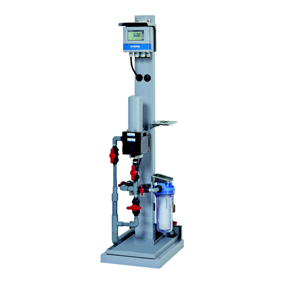
Page 94: Turbidity Sampling System
Data Turbidity sampling system Sampling system assembled with all the pipes necessary for turbidity measurement is available as an option. The following units can be installed for the piping assembly in addition to the manual valve for use in operation. Overflow tank ... - Page 95 Data Filter (for zero calibration) Precise zero calibration is necessary for the measurement of a low turbidity water, such as tap water or swimming pool water. The best way to keep errors to a minimum is to perform zero calibration while passing filtered clean water through the unit.
-
Page 96: Disposing Of The Instrument
Data Disposing of the instrument Dispose of this product in accordance with local laws, ordinances and regulations. Parts of this product are made of the following materials. 27 28 29 30 Name Material Name Material Nameplate 26 Warning plate Front cover ADC12 27 Switch ID plate Press-fit plunger... - Page 97 Data Name Material Name Material 18 LCD holder ADC12 43 Spacer C3604BD 19 Case packing 44 Printed circuit board (H4W-ANL-0x) Printed circuit board 20 Plunger packing R 45 PTFE plate PTFE 21 Parallel pin SUS304 46 Protective sheet U 22 Terminal nameplate 47 Upper hinge ADC12 23 Terminal block information plate PET...
-
Page 98: Display Of Turbidity Meter
Data Display of turbidity meter Display Description Display Description A.CAL Auto zero calibration by manual zero entry HoLd Hold Addr Address HoLd.t Holding time Alarm init Initialize Liquid crystal display Auto Auto range A.rEt Auto return b.out Burn out CAL.dAt Calibration data Normal Calibration menu CAL.E... - Page 99 Data Display Description Display Description Unit Unit User check menu 0.CAL Zero calibration...
-
Page 100: Quick Reference
Data Quick reference (appendix) Quick reference is a digest of the instruction manual. - Page 109 Headquarters 31, Miyanonishi-cho, Kisshoin Minami-ku, Kyoto, 601-8306 Japan TEL:+81-75-321-7184 FAX:+81-75-321-7291...
Need help?
Do you have a question about the HU-200TB-W SS-120-W and is the answer not in the manual?
Questions and answers