Table of Contents
Advertisement
Quick Links
Advertisement
Table of Contents

Related Manuals for horiba HU-200TB SS-120


Summary of Contents for horiba HU-200TB SS-120
- Page 1 Turbidity meter HU-200TB SS-120 Instruction Manual CODE:GZ0000230902...
- Page 2 HORIBA Advanced Techno, CO., Ltd. warrants that the Product shall be free from defects in material and workmanship and agrees to repair or replace free of charge, at option of HORIBA Advanced Techno, CO., Ltd., any malfunctioned or damaged Product attributable to responsibility of HORIBA Advanced Techno, CO., Ltd.
- Page 3 Regulations Conformable Directive This equipment conforms to the following directives and standards: Directives: the EMC Directive 2004/108/EC the Low Voltage Directive 2006/95/EC Standards: [the EMC Directive] EN61326-1: 2006 Class A, industry [the Low Voltage Directive] EN61010-1: 2001 Note If the sensor cable, transmission cable, or relay cable is extended to 30 m or more, the surge test in the EMC Directive for CE Marking is not applicable.
- Page 4 For Your Safety Hazard Classification and Warning Symbols Warning messages are described in the following manner. Read the messages and follow the instructions carefully. Hazard classification This indicates an imminently hazardous situation which, if not avoided, will result in death or serious injury. This signal word is to be limited to the most extreme situations.
- Page 5 If there is any corrosive gas in the installation environment, send clean instrumentation air through the air purge inlet on the HU-200TB SS-120. Operation outside the rated range can cause a fault. Therefore, check the power supply voltage.
- Page 6 Product Handling Information Operational Precautions Use of the equipment in a manner not specified by the manufacturer may impair the protection provided by the equipment. And it may also reduce equipment performance. Therefore, exercise the following precautions: Do not press any operation key with the tip of your nail or any pointed thing. Do not use organic solvent or the like.
-
Page 7: Table Of Contents
Contents Overview ..........Overview of equipment . - Page 8 Cleaning operation ......... Information for accurate measurements .
-
Page 9: Overview
Standard substances of turbidity are selectable from among Formazin, Kaolin, and Polystyrene Latex (PSL). The SS-120 detector for the HU-200TB SS-120 industrial-use turbidity meter can measure a turbidity with high stability because the fluctuations in light intensity and the changes in sensitivity of the detector are eliminated by using two LED light sources (660 nm) and two photo detectors. -
Page 10: Content
Overview Features of the Cleaner Electric reciprocating operation drive Silicon rubber wiper with high cleaning effect Operability by internal pressure CPU-based Intelligent motions Content Items included Name Illustration Quantity Remarks With bracket Converter 1 set With cover U-bolt: 2 M8 nut: 4 2 sets U... -
Page 11: Description Of Each Part (Converter)
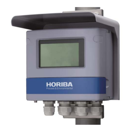
Overview Description of each part (Converter) Front view Cover Hood for outdoor Screw cap installation When the two screw caps are removed, the Display front case screws can be seen. The measured value and other information is displayed here. Front cover When the cover is opened, there are 6 operation keys. - Page 12 Overview Display Status display Measured value display - mg/L (the unit of a Kaolin SS concentration) - TURB (the unit of a “degree” of Status display turbidity) - FTU (Formazin) Indicator - Kaolin (Kaolin) - PSL (Polystyrene Latex) Auxiliary display Operation key section Terminal block RS-485 terminal...
-
Page 13: Description Of Operation Keys
Overview Description of operation keys The operation keys are used to toggle between displayed information, to enter any setting values, or to perform calibration work. When the indication is blinking, the figures and parameters can be changed. Use the ▲/▼ (UP/DOWN) key to select a blinking value or item, and then press the ENT key. The setting will flash and then be established. -
Page 14: Status Display
Overview Status display Status display Representation Display in text Description/Operation (meaning) Illuminated in the Hold mode (when the transmission output is held). HOLD Starts blinking when contact input is received or when the hold mode becomes active due to an error Illuminated when the Cal mode becomes active. -
Page 15: Description Of Operation Modes And Menu Items
Overview Description of operation modes and menu items This equimment offers three types of operation modes and four types of menus. Operation mode Meas. mode In this mode, samples are measured, and transmission signals and relays are controlled. Cal mode This mode allows you to perform zero calibration and span calibration. - Page 16 Overview Each mode and menu from Meas. mode Meas. mode The measurement output is held. Hold mode Hold down the HOLD key Setup menu See page 32. ▼ key See page 40. Cal menu ▼ key (turbidity calibration) User Check menu See page 42.
- Page 17 Overview Meas. mode Hold mode Hold down Hold down Setting Menu Check the contact output. Calibration Menu Check the User cleaning Check operation. Menu Check calibration data. Adjust a moving average.
-
Page 18: Description Of Each Part (Detector)
Overview Description of each part (Detector) Detector (SS-120) An automatic cleaner is optional.The options of automatic operation, manual operation, and non-cleaner can be selected. Automatic cleaner cover Sample outlet Cleaner locking screw Desiccant holder Sample inlet Exclusive use cable for the automatic cleaner U bolt 2 sets... - Page 19 Overview Automatic cleaner (optional) Automatic cleaner cover Pressure Knurled screw releasing hole Shaft Wiper Wiper holder Wiper support Span calibration bottle unit (optional) Calibration jig Calibration bottle...
-
Page 20: Installation
Installation Installation Installation environment To ensure the stable use of the HU-200TB SS-120 condition, install the HU-200TB SS-120 in a location that meets the following requirements. Instrument mainframe The location should be well ventilated to prevent build-up of moisture. The ambient temperature should be between −20°C and 55°C. -
Page 21: Installation Method
Installation Installation method The converter can be mounted on a pole (50 A) or a wall. Installation on a pole View of the HU-200TB SS- 120 mounted on a pole Maintenance [Unit: mm] area Installation on a wall 4-10 x 11 slot View of the HU-200TB SS-120 mounted on a wall... -
Page 22: Procedures For Connections
Installation Procedures for connections Opening the converter cover 1. Remove the two rubber-made screw caps located on the upper part of the front of the converter. Do not lose the removed screw caps. 2. Open the front cover. 3. Completely loosen the four screw located on the front of the converter. These screws will not drop off. -
Page 23: Connecting The Power Source
Installation Connecting the power source The converter has a power switch. The power source of the converter is a free power source for rated voltage of 100 V to 240 V AC. The terminal screw for the contact output is M4. The applicable electric wire is of 0.75 mm to 5.5 mm (AWG18 to AWG10). -
Page 24: Connecting The Contact Output Terminal
Installation Connecting the contact output terminal The contact capacity is lower than 250 V AC, 3 A or 30 V DC, 3 A at a resistance load. The terminal screw for the contact output is M4. The applicable electric wire is of 0.75 mm to 5.5 mm (AWG18 to AWG10). -
Page 25: Connecting The Contact Input Terminal
Installation RS-485 EXT.IN SENSOR OUT1 OUT1 (transmission output) Note The maximum load resistance for transmission output is 900 Ω . Connecting the contact input terminal The applicable electric wire is of 0.14 mm to 2.5 mm (AWG26 to AWG14). For a cable for contact input, use a twist pair shielded wire. If lighting might strike, install an arrester along the signal line. -
Page 26: Connecting The Communication Terminal
Installation Connecting the communication terminal Connecting the RS-485 terminal The converter has a RS-485 communication terminal. To use this terminal, connect the wiring. The applicable electric wire is 0.14 mm to 2.5 mm (AWG26 to AWG14). For the communication output cable, use a twisted shielded pair cable. Up to 32 connections can be made including the one for the host computer. -
Page 27: Connecting The Detector Cable
Installation Connecting the detector cable Precautions for the detector cable Turn OFF the power source during the connecting work. Connections The following terminals are available for the detector cable. +12 V 1: Power source 2: Power source 3: Communications + 4: Communications −... -
Page 28: Detector Installation Method
Installation Detector installation method Use the supplied U-bolts to attach the 2-inch (50 A) pipes. If the turbidity detector is installed at a height of approx. 1 m, it will make it much easier to operate. A special stand (optional) is used to temporarily hold a removed cleaner. -
Page 29: Flow
Installation Flow A through 20 A are suitable for the piping to the turbidity detector. In the turbidity detector, be sure to run samples upward from below. Install a valve (V-2) for flow rate adjustment at the outlet of the turbidity detector. If samples are supplied in-line and this valve is throttled, measurements can be made while pressure is maintained. - Page 30 Installation Method of using the overflow tank If an overflow tank is used for the SS measurement of drain water, lead a flow of samples to the overflow tank installed above the turbidity detector, and then lead a flow of the samples filtered with a rough mesh to the turbidity detector.
- Page 31 Installation In-line measuring method For measurement of tap water, etc., measuring inline can prevent the formation of air bubbles, and obtain even lower turbidity. To maintain sample pressure, throttle the valve on the outlet side. The flow rate decreases, but water pressure increases, thus suppressing the formation of air bubbles.
-
Page 32: Sampling Method
Installation Sampling method Type of sampling pumps For a sampling pump, be sure to select a centrifugal pump that can reduce the formation of rust. A pump in which exhalation pressure rises rapidly when the outlet of the pump is shut for maintenance purposes is not suitable for use. -
Page 33: Operation
Operation Operation Preparation for operation When this equipment is used for the first time, perform the following. Wiring check Check the installation status of sensors. Initial settings (the selection of working curve, settings for transmission signals, and settings for operating conditions of relay contacts) Calibration (zero calibration and span calibration) (Calibration after resetting is not needed required because calibration information is stored on the sensor side and is called up to the screen under energized conditions. - Page 34 Operation Initial setup The converter is shipped with initial settings from the factory. If it is necessary to make any change to the initial settings, make the settings in accordance with the instructions given in “ Entering the Setup menu ” (page 32). For the initial settings, see the table below.
- Page 35 Operation Note Before starting operation, be sure to make settings for the following items. Selection of the types of turbidity standard substances (selected from among Formazin, Kaolin, and Polystyrene Latex)
-
Page 36: Measurement
Measurement Measurement Meas. mode 1. Turn ON the power. The measurement object is displayed on the measured value display. The measurable range is displayed with the Meas. mode selected. If the detector is operating normally, measurements will be automatically started and measured values will be displayed on the screen. - Page 37 Measurement Meas. mode *Setup menu If “non” is selected from the "diSP" setting items, nothing is displayed in the sub-display part after returning to the Meas. mode. Controlled value setup Establishes menu Setting the value change Cancels the value Alarm settings can be changed during measurement.
- Page 38 Measurement Table 1 List of items displayed in Meas. mode Screen 1 Screen 2 Condition Description Action Remarks Measured values, the unit of measure, Measured value and the type of display screen standard turbidity substances are displayed. Relay Setting When rly Conditions screen “- - - - “...
- Page 39 Measurement Screen 1 Screen 2 Condition Description Action Remarks When This screen shows “- - - - “ indicates Cleaning that the automatic that the automatic “non” is cleaner is not used. cleaner is not used. Displays the time Cleaning operation before starting the 10 hours or longer standby time...
-
Page 40: Setup Menu
Measurement Setup menu The Setup menu allows you to select any parameters, standard turbidity standard substances for the detector and units of measure, and to define any display, transmission output, relays and communication addresses. Entering the Setup menu 1. In the Meas. mode, hold down the HOLD key until the HOLD indicator lights up. 2. - Page 41 Measurement Table 2 List of display items in the Setup menu Initial Screen 1 Screen 2 Description Setting range Remarks value Set the moving Increase dF to reduce the variations 1 to 120 average count in measured values. Decrease dF to times (damping factor) speed up the response.
- Page 42 Measurement Initial Screen 1 Screen 2 Description Setting range Remarks value Select the automatic changeover or fixed decimal point. "Auto" With a turbidity value, Auto moves the Decimal-point "1000" placement of the decimal point placement "Auto" "100.0" automatically.For the fixed zero point, (display range) "10.00"...
- Page 43 Measurement Initial Screen 1 Screen 2 Description Setting range Remarks value Specify a contact output type. "non": No output Relay 1 "non" "AL": Operates at alarm contact Relay 2 "AL" point. Set contact output "non" "HoLd" "Hold": Outputs during types ("r1" and "CLn"...
- Page 44 Measurement Initial Screen 1 Screen 2 Description Setting range Remarks value Set the FAIL Specify whether or not to trigger FAIL output when an output when an error is judged as an error is judged as "yES" "yES" abnormality by the self-check an abnormality by "no"...
- Page 45 Measurement Initial Screen 1 Screen 2 Description Setting range Remarks value Set the Selects a transmission output range. "10.00" ransmission A zero point and a full-scale point can "100.0" 10.00 output range be arbitrarily selected within the "1000" (Range) Range. The transmission output zero point Set the 0.00 to 10.00...
- Page 46 Measurement Initial Screen 1 Screen 2 Description Setting range Remarks value When the cleaner is detached, set the Set whether or use of the automatic cleaner to "no". not an automatic "no" Set the use of the automatic cleaner "no" cleaner will be "yES"...
- Page 47 Measurement For automatic cleaning, approx. 30 s per cycle are needed for the length of cleaning time. Once the cleaning operation has started, the cleaner continues to operate until the specified cleaning time ends, and then stops at a next top dead point. For example, if cleaning time length is set at 20 s, the cleaning operation ends in 1 stroke of reciprocating motion.
-
Page 48: Calibration Menu
Measurement Calibration menu The Calibration menu is used to perform the zero calibration and span calibration of the turbidity detector. As a rule of thumb, zero calibration and span calibration should be performed once a month. Entering the calibration menu Calibration can be performed by one of two methods: hold down the CAL key during measurement, or select the Calibration menu in the Hold mode. - Page 49 Measurement Table 3 List of displayed items in Calibration menu Calibration Screen 1 Screen 2 Description Action Remarks Type Pour zero water into the detector. At this time, if dirt in the accumulated water The current will impact the calibration, measured value wait for the zero water to blinks.The value...
-
Page 50: User Check Menu
Measurement User Check menu Entering the User Check menu allows you to check the display part or the transmission output, or to initialize the settings. Entering the User Check menu 1. In the Meas. mode, hold down the HOLD key until the HOLD indicator lights up. 2. - Page 51 Measurement Table 4 List of displayed items in User Check menu Screen 1 Screen 2 Description Action Remarks The whole LCD is Screen to check the illuminated, allowing you to check the display. Screen to check ON/OFF check of relay 1 relay output 1 ( “r1”...
- Page 52 Measurement Screen 1 Screen 2 Description Action Remarks Note that a set value reverts to a default Screen for initialization of Screen for value. setting data. initialization of After the initialization setting data and Select "yES" with the ▲/▼ is completed, the span calibration key, and press the ENT initial screen appears...
-
Page 53: Contact Output
Measurement Contact output Specify control operation for each of R1 and R2. The control items that can be specified vary depending on the selected output type. The items marked with a circle will be displayed as options. Selected type Screen Description "non"... - Page 54 Measurement Contact output types The following contact output types are available. "non" : No output This setting disables the contact output. Concentration alarm output When a measured value is continuously higher than a set value for triggering an alarm during delay time, an alarm is output (turning ON a relay) and the alarm will go off. Moreover, if a measured value is lower than a set value, alarm output is stopped (turning OFF a relay) and an alarm is released.
-
Page 55: Output Conditions Of Various Outputs
Measurement Output conditions of various outputs The output conditions of various outputs are shown below. Failure output Transmission output (Opened/Closed between CF-NCF) Contact output r1, r2 Status Self-check Over Burnout Burnout F.SC F,oF None Enabled HoLd Power-off Opened - When normal Enabled Closed Output... -
Page 56: Cleaning Operation
Measurement Cleaning operation Automatic cleaning is operated in accordance with the following conditions. Internal "CLn" "HoLd" External Cleaning cleaning Contact Contact Cleaning contact input operation Transmission cycle output output "CLn" type output ON: ○ ON: ◎ Cleaning:○ ON: ● ON: ●○ OFF: -... -
Page 57: Information For Accurate Measurements
Information for accurate measurements Information for accurate measurements This chapter provides information on maintenance aimed at ensuring accuracy, such as calibration methods. Zero calibration Cal mode Zero calibration is an operation adjusting the value of clean water to zero. The following calibration method is recommended, depending on the degree of turbidity. If low turbidity water (such as tap water or swimming pool water) is being measured, the turbidity resulting from air bubbles and matter adhering to the wall surfaces may make it difficult to accumulate zero water and calibrate it. -
Page 58: Selecting Turbidity Standard Substances
Information for accurate measurements 6. After zero calibration is completed, return to the Meas. mode. 7. Press the ESC key to return to the Meas. mode. Blinking Numeric value In the Zero Calibration mode, a negative measured value is also displayed. Selecting turbidity standard substances Select turbidity standard substances from among Kaolin, Formazin, and Polystyrene Latex. -
Page 59: Checking The Zero Calibration Data
Information for accurate measurements Checking the zero calibration data On the Calibration Data Check screen, checks can be made of the amount of transmitted light for zero calibration and the number of days elapsed since the date of the last zero calibration. A check of the amount of transmitted light makes a comparison with the initial amount of transmitted light. -
Page 60: Span Calibration
Moreover, an optional span calibration bottle for span calibration is also available from HORIBA Advanced Techno. If a span calibration bottle is used, signals as a substitute for a standard solution can be obtained simply by shaking and mixing the span calibration bottle strongly. - Page 61 Information for accurate measurements Span calibration procedure Pouring a standard liquid 1. Close the sample valve, and open the drain valve to discharge samples from the turbidity detector. 2. Detach the cleaner and wash the cell. 3. Wash the inside of the cell of the turbidity detector adequately. 4.
-
Page 62: Maintenance
Information for accurate measurements Maintenance Cleaning the detector Remove the cleaner, and clean the cell section of the detector with a soft brush, etc. When the detector becomes soiled, errors caused by flaking dirt become larger at the time of zero calibration. -
Page 63: Replacing The Wiper Rubber Of The Cleaner
Information for accurate measurements Replacing the wiper rubber of the cleaner. The wiper of the cleaner is made of silicone rubber. If the number of times of cleaning operations increases, a wiper will gradually change shape. Replace the wiper. As a rule, wipers should be replaced once a year for an automatic cleaner. WARNING Unexpected operation of the unit may result in damage to the unit or an injury. -
Page 64: Replacing The Motor Of The Cleaner
Information for accurate measurements Replacing the motor of the cleaner As a rule, replace the drive motor of an automatic cleaner once every three years. WARNING Unexpected operation of the unit may result in damage to the unit or an injury. Be sure to turn OFF the power when replacing consumables. - Page 65 Information for accurate measurements 8. Perform a test operation of the cleaner to check motions. (See page 31.) Motor assembly Connector Thrust bearing 9. Check all the screws in each section for looseness. 10. Wipe all dirt off the O-ring, place the cover on the O-ling, and tighten the screws. Note When screwing a stainless bolt into a female screw made of resin, do not apply a higher torque than necessary so that the screw is not damaged.
-
Page 66: Troubleshooting
Troubleshooting Troubleshooting Troubles with measurement Symptom Possible cause Remedial action Run zero water, and check variations. Add the turbidity standard solution, and check Non-uniformity of samples its difference from samples. Increase the numerical value of a dumping Fluctuation in factor, and check variations. measured value The sample’s particle size is large and Stir the sample. -
Page 67: Error Code
Troubleshooting Error code The converter has a function for displaying various error codes. A blinking error code is displayed on the auxiliary display. More than two types of errors cannot be displayed. If multiple errors occur, higher priority errors are displayed in the order in which they occur frequently. Description of error codes Error code Contents of error codes... -
Page 68: Reference Data
Reference data Reference data Specifications Converter Product name Industrial turbidity meter Converter type HU-200TB industrial-use turbidity converterfor Turbidity sensor SS-120 turbidity detector type Kaolin 0 to 500 degrees (Display range: 0 to 1100 degrees) Measurable range Formazin 0 to 1000 degrees (Display range: 0 to 1100 degrees) 0 to 100 degrees (Display range: 0 to 125 degrees) Arbitrary setting within the range from 0 to 1 degrees to 0 to 500 Kaolin... - Page 69 Reference data Number of input points 1 point Contact type Open collector no-voltage a contact ON resistance: 100 Ω max. (contact input) Condition Open-circuit voltage: 24 V DC Short-circuit current: 12 mA DC max. Contact capability Cleaning directive: Selection from transmission hold Type RS-485 Communication...
-
Page 70: Detector
Reference data Installation Outdoor installation type Installation method 50 A pole-mounted, or wall-mounted Protection class IP65 Material of case Aluminum alloy (coated with epoxy modified melamine resin) Structure Material of mounting SUS304 brackets Material of hood SUS304 (epoxy glue degeneration melamine resin painting) Material of display window Polycarbonate Display element Reflective monochrome LCD... -
Page 71: Measuring Principle
Reference data Measuring principle Two detectors alternately detect transmitted light and scattered light by using two LED light sources that blink alternately. While Light Source L1 is blinking, Detector D1 detects transmitted light and Detector D2 detects scattered light. While Light Source L2 is blinking, Detector D1 detects scattered light and Detector D2 detects transmitted light. - Page 72 Reference data Standardized Standard function of Formazin Turbidity of Formazin/1000 Next, obtain turbidity by using an expression (inverse function) that converts the value from α* (S/T-S0/T0) to a turbidity. Turbidity of Inverse function of Formazin Formazin/1000 Standardized S/T...
-
Page 73: Preparation Method Formazin 4000 Ftu
Reference data Preparation method Formazin 4000 FTU Setup and preparation Items to be prepared Agent: Sulfuric acid hydrazine, CAS 10034-93-2, Molecular formula: H6N2O4S (N2H4•H2SO4) Agent: Hexa methylene tetramine, CAS 100-97-0, Molecular formula: C6H12N4 Balance: The one that can measure 100 g with accuracy of 0.01 g. 500 mL beaker 1000 mL female flask Magnetic stirrer... -
Page 74: Preparation Method Of Kaolin Standard Solution
Reference data Preparation method of Kaolin standard solution Immediately after Kaolin is dissolved in water, because Kaolin particles contain air, the dispersion status is imperfect and turbidity is not stable. For this reason, prepare a strong liquid in advance, and leave it in water for the time being. Liquid A: Add 10 g of Kaolin to purified water, and prepare 10000 mg/L of Kaolin solution (Kaolin of 10000 degrees). -
Page 75: A Span Calibration Bottle (Optional)
Reference data A span calibration bottle (optional) Use of span calibration bottles (optional) Even if a span standard solution is not prepared, span calibration is possible in the method of inserting a span calibration bottle in the cell that is filled with water. While the turbidity of a span standard solution is already known, the turbidity of a span calibration bottle is not already known. -
Page 76: Turbidity Sampling System (Optional)
Turbidity sampling system (optional) All the pipes needed for turbidity measurement have been assembled into an optional product that can be purchased from HORIBA Advanced Techno. The following additional units can be attached to a piping assembly in addition to a manual valve for use in operation. - Page 77 Reference data Filter Precise zero calibration is needed for the measurement of a low turbidity water, such as tap water and swimming pool water. The method of performing zero calibration while passing filtered samples through the unit is the best way to keep errors to a minimum. As for the type of filters, a precise filter or an ultra filter is suitable for use.
- Page 78 Reference data Piping assembly with filters and an OF tank Referential flow schematic Power source (90 V to 260 V AC) Zero filter unit (optional)
-
Page 79: Disposal Method
Reference data Disposal method When disposing of a converter, be sure to do so in accordance with local laws, ordinances and regulations. The parts of a converter are made of the following raw materials. Name Material Name Material Nameplate Switch ID plate Front cover ADC12 Terminal cover L... - Page 80 Reference data Name Material Name Material Printed circuit board (H4W- Printed circuit LCD holder ADC12 ANL-0x) board Case packing PTFE plate PTFE Plunger packing R Protective sheet U Parallel pin SUS304 Upper hinge ADC12 Terminal nameplate Screw cap 2 Terminal block information Functional ground information plate plate...
-
Page 81: Display Of Turbidity Meter
Reference data Display of turbidity meter Display English Addr Adress Alarm Auto Auto range A.rEt Auto return b.out Burn out CaL.dAt Calibration data Calibration menu Clean CLn.t Cleaning type 1.CLn.t Cleaning type of 1 2.CLn.t Cleaning type of 2 Clear Curr Current C.HoLd... - Page 82 Reference data Display English out.20 Output 20 out.4 Output 4 PArA Parameter PtnA Pattern A Ptnb Pattern B Polysterene latex PrES Preset rng.C Range cut 1.rng Range of relay 1 2.rng Range of relay 2 rng.S Range span rng.0 Range zero Relay Relay 1 Relay 2...
- Page 83 Headquarters 31, Miyanonishi-cho, Kisshoin, Minami-ku, Kyoto, 601-8306 TEL:+81-75-321-7184 FAX:+81-75-321-7291 Tokyo Office 4F Higashikanda Fukoku Seimei Building, 1-7-8, Higashikanda, Chiyoda-ku, Tokyo, 101-0031 TEL:+81-3-3851-3150 FAX:+81-3-3851-3140 Nagoya Office 6F Sumitomo Seimei Chikusa 2nd Building, 3-15-31, Aoi, Higashi-ku, Nagoya, 461-0004 TEL:+81-52-937-0812 FAX:+81-52-937-0675...
Need help?
Do you have a question about the HU-200TB SS-120 and is the answer not in the manual?
Questions and answers