Table of Contents
Advertisement
Quick Links
Wireless Pushbutton Switch
User's Manual
A2W-R-WC1
A2W-T-WC1
1
Operating
Procedure
2
Overview
3
Survey of the Operating
Environment and
System Design
4
Installation and Wiring
of the Master Unit
5
Registration
in the ID Mode
6
Wireless Test
in the TEST Mode
7
Run in the
RUN Mode
8
Trouble Shooting
A
Appendix
A265-E1-01
Advertisement
Table of Contents

Subscribe to Our Youtube Channel
Related Manuals for Omron A2W-R**-WC1 Series


Summary of Contents for Omron A2W-R**-WC1 Series
- Page 1 Operating Procedure Overview Wireless Pushbutton Switch Survey of the Operating Environment and System Design Installation and Wiring User's Manual of the Master Unit A2W-R-WC1 Registration A2W-T-WC1 in the ID Mode Wireless Test in the TEST Mode Run in the RUN Mode Trouble Shooting Appendix A265-E1-01...
- Page 2 No patent liability is assumed with respect to the use of the information contained herein. Moreover, because OMRON is constantly striving to improve its high-quality products, the information contained in this manual is subject to change without notice. Every precaution has been taken in the preparation of this manual. Neverthe- less, OMRON assumes no responsibility for errors or omissions.
-
Page 3: Preface
Keep this manual in a safe place for easy reference. PDF version of this manual can be downloaded from the OMRON website. (http://www.ia.omron.com) -
Page 4: Terms And Conditions Agreement
Omron’s exclusive warranty is that the Products will be free from defects in materials and workman- ship for a period of twelve months from the date of sale by Omron (or such other period expressed in writing by Omron). Omron disclaims all other warranties, express or implied. -
Page 5: Application Considerations
Disclaimers Performance Data Data presented in Omron Company websites, catalogs and other materials is provided as a guide for the user in determining suitability and does not constitute a warranty. It may represent the result of Omron’s test conditions, and the user must correlate it to actual application requirements. Actual perfor- mance is subject to the Omron’s Warranty and Limitations of Liability. -
Page 6: Safety Precautions
Safety Precautions Safety Precautions Definition of Precautionary Information The following notation is used in this manual to provide precautions required to ensure safe usage of a Wireless Pushbutton Switch. The safety precautions that are provided are extremely important to safety. Always read and heed the information provided in all safety precautions. The following notation is used. - Page 7 Safety Precautions WARNING Do not use this product without a protection circuit. Otherwise it may result in heavy injuries or dam- age on life or property due to malfunction. Dual or triple safety protection circuits, such as emergency stop, interlock, or limit circuit, must be configured by external control circuit so that the system should operate on safe side even if a failure of this product or an error due to an external factor occurred.
-
Page 8: Precautions For Safe Use
To prevent damage from falls, OMRON recommends securing this product with screws when mount- ing it on walls, etc. Stop using this product if it is subjected to strong impacts. - Page 9 Precautions for Safe Use (21) Do not tilt or twist a flat-blade screwdriver while it is inserted into a release hole on the terminal block. The terminal block may be damaged. (22) Do not allow the flat-blade screwdriver to fall out while it is inserted into a release hole. (23) Insert a flat-blade screwdriver into the release holes at an angle.
- Page 10 Precautions for Safe Use Slave button (1) The switching function performance may be insufficient. Do not drop the product. (2) When storing this product, avoid hazardous gases (H S, SO , NH , HNO , Cl , etc.), dust, high temperature and high humidity.
-
Page 11: Precautions For Correct Use
Precautions for Correct Use Precautions for Correct Use Always heed these precautions to prevent faulty operation, malfunction, or adverse affect on the prod- uct's performance and functionality. Master Unit (1) Communications performance may be affected by its environment. Always confirm its operation before using it. - Page 12 Precautions for Correct Use Slave button (1) Check the indicators of the product in the following cases. The product was stored outside the environmental conditions, condensation has occurred in the product, the product has been dropped, or the product stored for more than one year for a long time. (2) Do not operate excessive force to the product.
-
Page 13: Revision History
Revision History Revision History A manual revision code appears as a suffix to the catalog number on the front and back covers of the manual. A265-E1-01 Revision code Revision code Date Revised content December 2017 Original production Wireless Pushbutton Switch User’s Manual (A265) - Page 14 Revision History Wireless Pushbutton Switch User’s Manual (A265)
-
Page 15: Sections In This Manual
Sections in this Manual Sections in this Manual Operating Procedure Overview Survey of the Operating Environment and System Design Installation and Wiring of the Master Unit Registration in the ID Mode Wireless Test in the TEST Mode Run in the RUN Mode Trouble Shooting Appendix Wireless Pushbutton Switch User’s Manual (A265) -
Page 16: Table Of Contents
CONTENTS CONTENTS Preface ........................1 Terms and Conditions Agreement ................2 Warranty, Limitations of Liability ........................2 Application Considerations .......................... 3 Disclaimers ..............................3 Safety Precautions ....................4 Definition of Precautionary Information......................4 Symbols ............................... 4 Precautions for Safe Use ..................6 Precautions for Correct Use.................. -
Page 17: Contents
CONTENTS Section 3 Survey of the Operating Environment and System De- sign Installation and Operating Environment ................3-2 Operation Timing Chart ......................3-5 3-2-1 Operation Timing Chart ......................3-5 Section 4 Installation and Wiring of the Master Unit Dimensions ..........................4-2 4-1-1 Master Unit .......................... - Page 18 CONTENTS Appendix A-1 Slave Button Registration Management Sheet ..............A-2 Wireless Pushbutton Switch User’s Manual (A265)
-
Page 19: Operating Procedure
Operating Procedure This section describes how to use the wireless pushbutton switches system. 1-1 Overall Operating Procedure ........1-2 1-1-1 Overall Flowchart . -
Page 20: Overall Operating Procedure
1 Operating Procedure Overall Operating Procedure This section describes the overall flow of use of the wireless pushbutton switches system. 1-1-1 Overall Flowchart The wireless pushbutton switches system, which consists of the A2W-R-WC1 Mater Unit and A2W-T-WC1 Slave button, can be used with the following procedure. For details, refer to each sec- tion. -
Page 21: Overview
Overview This section describes the overview of the wireless pushbutton switches system and the nomenclature. 2-1 Overview and Features ......... 2-2 2-1-1 Overview . -
Page 22: Overview And Features
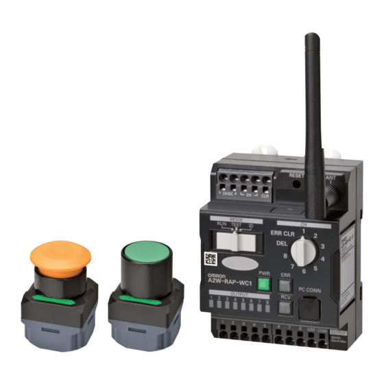
2 Overview Overview and Features This section describes the overview and features of the wireless pushbutton switches system. 2-1-1 Overview The wireless pushbutton switches system consists of A2W-R-WC1 Master Units and A2W-T-WC1 Wireless Pushbutton Switches. At the push button switches side, it has no wiring (i.e., wireless) and no power supply. -
Page 23: Features
2 Overview 2-1-2 Features The Wireless pushbutton switch system has the following features. • Up to eight Slave buttons (pushbutton switches) can be assigned to one Master Unit. • Self-power generation by button operation eliminates the power supply for Slave buttons (pushbutton switches). -
Page 24: System Configurations
2 Overview System Configurations This section describes the system configurations of the wireless pushbutton switches. Precautions for Correct Use After pressing a Slave button, wait for 100 ms before pressing the next Slave button, because the Master Unit can not receive at the same time signals of multiple Slave buttons. 2-2-1 Using the Pencil Antenna Standard Included The system configuration diagram when the Pencil antenna is connected to the Master Unit is shown... -
Page 25: Using Optional High-Sensitivity Magnetic-Base Antenna
2 Overview 2-2-2 Using Optional High-sensitivity Magnetic-base Antenna The following is a system configuration diagram when the High-sensitivity Magnetic-base Antenna is connected to the Master Unit. System Configuration High-sensitivity Magnetic-base Antenna (A2W-AT2.5-WC1) Master Unit 24 VDC power supply A2W-R -WC1 RCV LED Received signal: Received field strength is "Strong"... -
Page 26: Relationship Between Slave Buttons And Master Unit
2 Overview 2-2-3 Relationship Between Slave Buttons and Master Unit Up to 8 Slave buttons can be assigned to one Master Unit. A single Master Unit can output eight transistors. • A single Slave button can be assigned to each output of the Master Unit. •... - Page 27 2 Overview (b) A single Slave button can be assigned to multiple outputs of the Master Unit in duplicate. Master Unit A2W-R -WC1 Multiple transistor outputs ON/OFF Data Confirm reception Slave button A2W-T -WC1 For details, refer to the 2-5-4 Assignment Relationship Between Slave Button and Outputs of Master Unit on page 2-18.
-
Page 28: List Of Models
929.2 MHz 868.3 MHz 922.5 MHz Output Configuration Sinking output Sourcing output Protocol OMRON's protocol Area Japan United States or Canada Mexico Europe (EU) Brazil Note Be sure to use the models for the corresponding area. When used in a country other than the correspond- ing area, it becomes illegal under the radio law of each country. -
Page 29: Slave Button And Options
A2W- - WC (5) (6) Number Type Symbol Specifications Slave button Frequency 929.2 MHz 868.3 MHz 922.5 MHz Protocol OMRON’s protocol Area Japan United States or Canada Mexico Europe (EU) Brazil Button appearance Mushroom Full guard Button color Green Yellow... -
Page 30: Nomenclature And Functions
2 Overview Nomenclature and Functions This section describes the nomenclature and functions of the Master Unit and Slave buttons of the wire- less pushbutton switches system. 2-4-1 Master Unit Nomenclature A B C D E F G H I J K M N O Terminal Number... - Page 31 2 Overview Terminal Number Name Function name Reset switch • Delete the Slave button registration information corresponding to the output settings switch. • By pressing the output settings switch in the "ERR CLR" state when an error output is generated, error output will be reset. •...
- Page 32 2 Overview Enabled Color Status Meaning name mode OUTPUT Yellow RUN/TEST Data is received from the ID assigned to the corresponding output Not lit Data is not received from the ID assigned to the corresponding output 1 to 8 Reads corresponding output settings switch values 1 to 8 All lit Reads output settings switch value DEL All not lit...
- Page 33 2 Overview Setting Switches Mode Settings Switch Set the operation mode of the Master Unit. Factory setting: ID Operation Function mode Communications mode: Normal communications TEST Test mode: Installation tests such as reception strength measurement, etc. * There is no output from the output terminal. ID mode: Register or delete Slave buttons ...
-
Page 34: Slave Button
2 Overview 2-4-2 Slave Button Nomenclature Button Flange Reception confirmation LED Slave button ID Reception Confirmation LED Display color Description Green Transmission/reception success (Strength of receiving field: Strong) Yellow Transmission/reception success (Strength of receiving field: Weak) Transmission/reception failure Not lit Slave button malfunction (No signal transmission from the Slave button) Precautions for Correct Use If a Slave button are assigned to multiple Master Units, the reception confirmation LED on the... -
Page 35: Specifications And Functions
2 Overview Specifications and Functions This section shows the wireless specifications of the wireless pushbutton switches system, the Master Unit, and the Slave button. 2-5-1 Wireless Specifications The specifications of the radio used with the wireless pushbutton switches system are as follows. Slave button model A2W-TA-WC1 JP... -
Page 36: Ratings
2 Overview 2-5-2 Ratings The ratings of the Master Unit and Slave buttons are as follows. Master Unit Item Specifications Rated voltage 24 VDC Allowable voltage 21.6 to 26.4VDC Master Unit range power supply Current consumption 2.4 W max. Input current 0.1 A max. - Page 37 2 Overview Output Circuits Diagram of the Power Supply Terminals Output/Error output circuits diagram (sinking) Output/Error output circuits diagram (sourcing) OUT1 OUT1 OUT8 OUT8 Slave Button Item Specifications Operating force 25 N max. Number of operations 1,000,000 operations Vibration resistance Frequency: 10 to 55 Hz, 0.75-mm single amplitude for 2 h, sweeps of 5 min.
-
Page 38: Operation Mode
2 Overview 2-5-3 Operation Mode The Master Unit has the following operation modes. Operation mode Mode name Function Communications Receives data from the Slave button and performs transistor output. mode (During normal operation) TEST Test mode Even if data is received from the Slave button, transistor output is not performed. - Page 39 2 Overview One Slave Button is Assigned to Two or More Outputs Output No. 2 Output No. 3 Output No. 4 Input Output No. 2 Master Unit Output No. 3 Example: Output No. 4 Slave button (a) is assigned to output Slave No.
- Page 40 2 Overview 2 - 20 Wireless Pushbutton Switch User’s Manual (A265)
- Page 41 Survey of the Operating Environ- ment and System Design This section describes how to check the operating environment of the wireless push- button switches system. 3-1 Installation and Operating Environment ......3-2 3-2 Operation Timing Chart .
-
Page 42: Installation And Operating Environment
3 Survey of the Operating Environment and System Design Installation and Operating Environ- ment This section describes the installation and operating environment of the wireless pushbutton switches system. Before installing the Wireless Pushbutton switches System, make sure to confirm that the radio ware condition at the installation site is good by temporarily installing. - Page 43 3 Survey of the Operating Environment and System Design Installation Locations When selecting the installation locations of the Master Units, consider the following conditions: • 24 VDC power supply can be supplied to the Master Unit • To set the Master Unit at a relatively high position. When installing the Master Unit on the floor, the communications distance becomes short.
- Page 44 3 Survey of the Operating Environment and System Design Major Radio Wave Obstacles in the Buildings • Floor and ceiling metal plates and piping • Metal shielding (iron door, metallic shutter, etc.) • Thermal insulation (cover with aluminum vapor deposition) •...
-
Page 45: Operation Timing Chart
3 Survey of the Operating Environment and System Design Operation Timing Chart This section describes the operation timing between the Master Unit and the Slave buttons of the wire- less pushbutton switches system. 3-2-1 Operation Timing Chart Press operation Slave button Slave reception confirm LED Master Unit... - Page 46 3 Survey of the Operating Environment and System Design 3 - 6 Wireless Pushbutton Switch User’s Manual (A265)
- Page 47 Installation and Wiring of the Mas- ter Unit This section describes installation and wiring of the wireless pushbutton switch. 4-1 Dimensions ........... 4-2 4-1-1 Master Unit .
-
Page 48: Dimensions
4 Installation and Wiring of the Master Unit Dimensions This section describes the external dimensions of components of the wireless pushbutton switches sys- tem. 4-1-1 Master Unit Master Unit Device Unit: mm 34.5 (4.5) 108 * * When installing the wall (161.5) (79.1) (60.8) - Page 49 4 Installation and Wiring of the Master Unit Option (sold separately) A2W-AT2.5-WC1 High-sensitivity Magnetic-base Antenna 3 dia. 1.2 dia. ±3 +100 27 dia. 2500 ±2 4 - 3 Wireless Pushbutton Switch User’s Manual (A265)
-
Page 50: Slave Button
4 Installation and Wiring of the Master Unit 4-1-2 Slave button Slave button Device Mushroom A2W--WC1-1 65 max. 40 dia. Two, M3×6 Fine thread 26.5 35.2 (2.5) Full guard A2W--WC1-2 65 max. 34.4 dia. Two, M3×6 Fine screw 26.5 35.2 (2.5) - Page 51 4 Installation and Wiring of the Master Unit Accessories (sold separately) Slave Button Holder A2W-H-WC1 (One A2W-H-WC1 is bundled when purchasing the Slave button.) Four-5.6 dia. 46.6 60.3 Mounting Hole Dimensions Two, M5 screw hole or 5.2-dia. mounting hole 24.8 24±0.1 46.3...
-
Page 52: Installing Master Units
Secure each DIN rail inside a control panel with at least three screws. Secure the DIN Rail Recommended DIN rail Model Dimensions Manufacturer PFP-100N 1,000 mm OMRON PFP-50N 500 mm DIN Rail End Plates PFP-M (2 required) 4 - 6 Wireless Pushbutton Switch User’s Manual (A265) - Page 53 4 Installation and Wiring of the Master Unit Installation direction A Master Unit can be installed in any of the following orientations. Horizontal (Face-up Mounting): OK Horizontal Vertical: OK (Face-down Mounting): OK Side: OK Vertical: NG <Face-up Mounting> <Standard mounting> <Face-down Mounting>...
-
Page 54: Screw Mounting
4 Installation and Wiring of the Master Unit How to remove Master Unit Pull down on the hook with a flat-blade screwdriver and lift up on then the Master Unit. 25 mm above 4-2-2 Screw Mounting How to install Master Unit (1) Pull out the three hooks at the back of the product toward the outside until a sound is heard. -
Page 55: Connecting Wires To Push-In Plus Terminal Block
4 Installation and Wiring of the Master Unit Connecting Wires to Push-In Plus Terminal Block This section describes how to connect to the push-In Plus terminal block of the Master Unit. Precautions for Safe Use • To prevent wiring materials from smoking or ignition, confirm wire ratings and use the wiring materials given in the following table. -
Page 56: Push-In Plus Terminal Block
4 Installation and Wiring of the Master Unit 4-3-2 Push-In Plus Terminal Block Item Specifications Hands free Construction Front-in front and front-release Applicable wires Stranded wires, solid wires, or ferrules Applicable wire size 0.25 to 1.5 mm (AWG24 to AWG14) Wire insertion force 8 N max. -
Page 57: Removing Wires From The Push-In Plus Terminal Block
4 Installation and Wiring of the Master Unit Connecting Stranded Wires Use the following procedure to connect the wires to the terminal block. Hold a flat-blade screwdriver at an angle and insert it into the release hole. The angle should be between 10° and 15°. If the flat-blade screwdriver is inserted correctly, you will feel the spring in the release hole. -
Page 58: Recommended Ferrules And Crimp Tools
4 Installation and Wiring of the Master Unit 4-3-5 Recommended Ferrules and Crimp Tools Recommended ferrules Applicable wire Ferrule Stripping Recommended ferrules Conduc- length (mm) Manufactured by Manufactured by Manufactured by tor length (Ferrules Phoenix Contact Weidmuller Wago (mm) used) 0.25 AI 0,25-8 H0.25/12... - Page 59 SZF 0-0.4×2.5 0.4×2.5×75 302 Wiha AEF.2,5×75 Facom 210-719 Wago SDI 0.4×2.5×75 Weidmuller *1. OMRON's exclusive purchase model XW4Z-00B is available to order as SZF 0-0.4 x 2.5 (manufactured by Phoenix Contact). 4 - 13 Wireless Pushbutton Switch User’s Manual (A265)
-
Page 60: I/O Wiring Of The Master Units
4 Installation and Wiring of the Master Unit I/O Wiring of the Master Units This section describes how to wire the wireless pushbutton switch Master Unit. 4-4-1 Power Supply input Wiring Power must be supplied to the Master Unit. Power terminal Error clear terminal (Upper left part of the Master Unit) The power input terminal is the push-in Plus terminal. -
Page 61: Wiring Of Error Output
4 Installation and Wiring of the Master Unit 4-4-3 Wiring of Error Output The master unit has one output terminal at error. Error output Transistor output Error output Output contact Error output terminal Transistor output common (Lower part of Mater Unit) The error output terminal is the Push-In Plus terminal. - Page 62 4 Installation and Wiring of the Master Unit 4 - 16 Wireless Pushbutton Switch User’s Manual (A265)
-
Page 63: Registration In The Id Mode
Registration in the ID Mode This section describes how to register the Slave buttons to the Master Unit in the wire- less pushbutton switches system. 5-1 How to Register Slave Buttons to Master Unit ..... . 5-2 5-1-1 Steps to Register the Slave Buttons . -
Page 64: How To Register Slave Buttons To Master Unit
5 Registration in the ID Mode How to Register Slave Buttons to Master Unit This section describes how to register/delete the Slave buttons to/from the Master Unit. In ID mode, you can register Slave buttons to the Master Unit. Precautions for Correct Use •... -
Page 65: Steps To Register The Slave Buttons
5 Registration in the ID Mode 5-1-1 Steps to Register the Slave Buttons Register the Slave button one by one. Register operation is performed on both Master Unit and Slave buttons. If you want to register multiple Slave buttons to the same output number of one Master Unit, repeat the operation for a Slave button one by one as shown below. - Page 66 5 Registration in the ID Mode Procedure Set the "mode settings switch" of the Master Unit to "ID" (ID mode). Mode settings switch Set the "output settings switch" of the Master Unit to (e.g., 1). Example 1 Output settings switch The output LED (e.g., OUTPUT 1) of the Master Unit will turn yellow.
-
Page 67: How To Delete Slave Buttons
5 Registration in the ID Mode 5-1-2 How to Delete Slave Buttons There are three ways to delete the Slave button as follows. Note: Whether or not to implement How to delete Slave buttons when the Slave button fails Delete all Slave buttons together Possible Delete a specific Slave button Not possible... - Page 68 5 Registration in the ID Mode Delete All the Slave Buttons Registered in the Specific Output Together Example: When the Slave button # 1 and # 2 are assigned to the output No. 1 of the Master Unit, the output No.
- Page 69 5 Registration in the ID Mode Procedure Set the "mode setting switch" of the Master Unit to "ID" (ID mode). Mode settings switch Set the "output setting switch" of the Master Unit to ”DEL”. Output settings switch All the output LEDs of the Master Unit will turn yellow. All LEDs turn yellow.
- Page 70 5 Registration in the ID Mode Delete a Specific Slave Button Delete operations are performed on both the Master Unit side and the specific Slave button. When the Slave button to delete is assigned to multiple output numbers of the Master Unit, Slave buttons are deleted from multiple output numbers at once.
- Page 71 5 Registration in the ID Mode Procedure Set the "mode settings switch" of the Master Unit to "ID" (ID mode). Mode settings switch Set the "output settings switch" of the Master Unit to ”DEL”. Output settings switch All the output LEDs of the Master Unit will turn yellow. All LEDs turn yellow.
- Page 72 5 Registration in the ID Mode Delete ALL the Slave Buttons Registered to the Specific Output Together Delete operation is performed only on the Master Unit side. When multiple Slave buttons are registered in the output No. of the Master Unit to be deleted, multiple Slave buttons are deleted together.
- Page 73 5 Registration in the ID Mode Procedure Set the "mode settings switch" of the Master Unit to "ID" (ID mode). Mode settings switch Set the "Output settings switch" of Master Unit to one of the ID "1" to "8" of the Slave button you want to delete.
- Page 74 5 Registration in the ID Mode 5 - 12 Wireless Pushbutton Switch User’s Manual (A265)
-
Page 75: Wireless Test In The Test Mode
Wireless Test in the TEST Mode This section describes the wireless test execution method of the wireless pushbutton switches system. 6-1 Wireless Test ..........6-2 6 - 1 Wireless Pushbutton Switch User’s Manual (A265) -
Page 76: Wireless Test
6 Wireless Test in the TEST Mode Wireless Test This section describes the wireless test procedure of the wireless pushbutton switches system. In TEST mode, you can perform a wireless test. In TEST mode, the Master Unit does not output even when receiving an operation signal from the Slave buttons. - Page 77 6 Wireless Test in the TEST Mode Procedure Set the "mode settings switch" of the Master Unit to "TEST" (TEST mode). TEST Mode settings switch Press the Slave button that you want to test. Slave button When the Slave button is pressed and if transmission and reception with the Master Unit is successful, the reception confirmation LED of the Slave button will light green.
- Page 78 6 Wireless Test in the TEST Mode When the reception field Strength is “Strong”, the RCV LED of the Master Unit will light green for 0.5 seconds. When the reception field Strength is “Week”, the RCV LED of the Master Unit will light yellow for 0.5 seconds.
-
Page 79: Run In The Run Mode
Run in the RUN Mode This section describes how to run the wireless pushbutton switches system. 7-1 Operation ........... . 7-2 7 - 1 Wireless Pushbutton Switch User’s Manual (A265) -
Page 80: Operation
7 Run in the RUN Mode Operation This section describes how to actually operate the wireless pushbutton switches system. In RUN mode, you can perform actual wireless communications. Use this mode for regular operations. Operation Procedure Flowchart <Master Unit> <Slave buttons>... - Page 81 7 Run in the RUN Mode Procedure Set the "mode settings switch" of the Master Unit to "RUN" (RUN mode). Mode settings switch Press the Slave button registered in the Master Unit. Slave button When the Slave button is pressed and if transmission and reception with the Master Unit is successful, the reception confirmation LED of the Slave button will light green.
- Page 82 7 Run in the RUN Mode When the reception field Strength is “Strong”, the RCV LED of the Master Unit will light green for 0.5 seconds. When the reception field Strength is “Week”, the RCV LED of the Master Unit will light yellow for 0.5 seconds.
-
Page 83: Trouble Shooting
Trouble Shooting This section describes troubleshooting when using the wireless pushbutton switches system. 8-1 Trouble Situations and How to Implement Countermeasures ..8-2 8-1-1 Troubles at Installation or Operation ....... . . 8-2 8-1-2 LED Indication When Trouble Occurs . -
Page 84: Trouble Situations And How To Implement Countermeasures
8 Trouble Shooting Trouble Situations and How to Imple- ment Countermeasures This section describes trouble situations of the wireless pushbutton switches system and how to imple- ment countermeasures. 8-1-1 Troubles at Installation or Operation Situation Possible cause Troubleshooting methods Master Unit’s power is not turned The power supply terminal of the Correctly connect again. - Page 85 8 Trouble Shooting Situation Possible cause Troubleshooting methods It is in an installation environment It is installed in a building whose In operating environments where radio where radio waves hardly reach. entire wall is covered with a metal wave obstacles can not be avoided, con- plate.
-
Page 86: Led Indication When Trouble Occurs
8 Trouble Shooting 8-1-2 LED Indication When Trouble Occurs Master Unit PWR lighting state Status Troubleshooting methods Not lit Power is not supplied to Master Refer to the Master Unit’s power is not Unit. turned ON. on page 8-2 in 8-1-1 Trou- bles at Installation or Operation on page 8-2. -
Page 87: Master Unit Error
8 Trouble Shooting Master Unit Error This section describes the status of the Master Unit error occurrence and how to Implement counter- measures. 8-2-1 Error Status of the Master Unit If an error occurs in the Master Unit, an error signal is output from the error output terminals. At the same time, an error message will be displayed. -
Page 88: How To Return Master Unit To Factory Setting
8 Trouble Shooting Error Clear Input Make short the Master Unit error clear terminal to 0 V. Power supply terminals Error clear terminal (Upper left part of Master Unit) The voltage between the error clear terminal and 0 V must be 15 VDC or less to reset the error. The error clear terminal and 0 V are the Push-In Plus terminals. -
Page 89: Replacing Master Unit
8 Trouble Shooting Replacing Master Unit This section describes how to replace the Master Unit of the wireless pushbutton switch. 8-3-1 How to Replace Master Unit Make a note of the current Master Unit status. Number of Slave buttons, ID of Slave button, wiring of external output, etc. Remove all Master Unit wiring. - Page 90 8 Trouble Shooting 8 - 8 Wireless Pushbutton Switch User’s Manual (A265)
- Page 91 Appendix A-1 Slave Button Registration Management Sheet ..... . A-2 A - 1 Wireless Pushbutton Switch User’s Manual (A265)
- Page 92 Appendix A-1 Slave Button Registration Manage- ment Sheet Use this sheet to record the Slave buttons to be registered in the Master Unit. Copy the next page. <Entry example> Master Unit #: Name of equipment etc.: Date: Month: Year: Organization: Name: Master Unit Output Number Slave button...
- Page 93 Appendix Master Unit #: Name of equipment etc.: Date: Month: Year: Organization: Name: Master Unit Output Number Slave button Name (Remarks) Master Unit #: Name of equipment etc.: Date: Month: Year: Organization: Name: Master Unit Output Number Slave button Name (Remarks) Master Unit #: Name of equipment etc.:...
- Page 94 Appendix A - 4 Wireless Pushbutton Switch User’s Manual (A265)
- Page 96 The Netherlands Hoffman Estates, IL 60169 U.S.A. Tel: (31)2356-81-300/Fax: (31)2356-81-388 Tel: (1) 847-843-7900/Fax: (1) 847-843-7787 © OMRON Corporation 2017 All Rights Reserved. OMRON (CHINA) CO., LTD. OMRON ASIA PACIFIC PTE. LTD. In the interest of product improvement, Room 2211, Bank of China Tower, No.
Need help?
Do you have a question about the A2W-R**-WC1 Series and is the answer not in the manual?
Questions and answers