Table of Contents
Advertisement
Quick Links
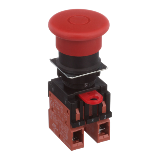
Emergency Stop Switch
A22E
Install in 22-dia. or 25-dia.
Panel Cutout
• Direct opening mechanism with minimum
contact separation of 3 mm in accordance with
EN60947-5-1,
. (only for NC contacts)
Æ
• Safety lock mechanism prevents misuse.
(No tampering – in accordance with EN 418)
• Easy mounting and removal of Switch Blocks
using an incorporated lever.
• Finger protection mechanism on Switch Unit
provided as a standard feature.
• Install using either round, forked crimp terminals,
or ferrules.
For additional installation of emergency-stop switches.
Emergency-stop switches can be
installed easily far from machines.
A22E
A22Z-3466-1
A22E-#-#
A22Z-B101Y
Control Box
G-303
Advertisement
Table of Contents


Need help?
Do you have a question about the A22E-MP and is the answer not in the manual?
Questions and answers