Table of Contents
Advertisement
Quick Links
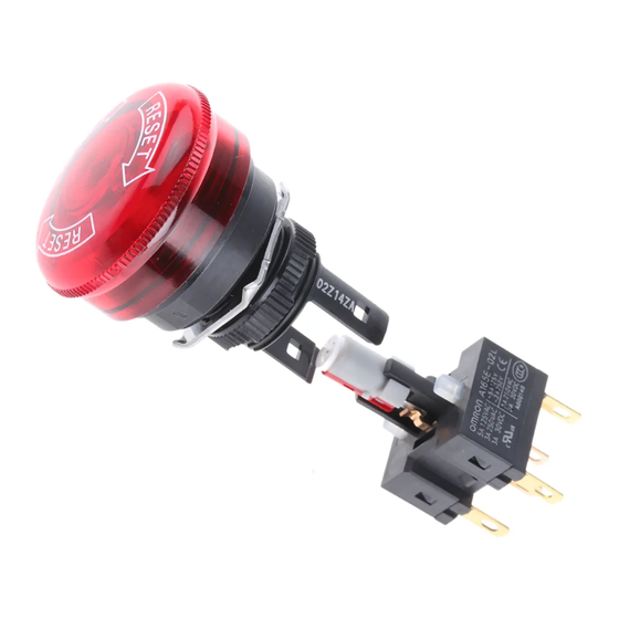
Emergency Stop Switch (16-dia.)
A165E
Separate Construction with Smallest
Class of Depth in the World
■ Direct opening mechanism to open contacts in emergencies,
such as when they are welded.
■ Conforms to EN418.
■ Includes a safety lock to prevent misuse.
■ Features separate construction that allows the Switch to be
separated for easier wiring and one-piece-like construction
that allows easier handling.
■ Models available with 3 contacts built into a single block
(A165E-U).
Be sure to read the precautions for all pushbutton switches
in the Pushbutton Switches Group Catalog (Cat. No. X032),
as well as the "Safety Precautions" on page 9.
Model Number Structure
List of Models
Diameter of
Function
Operation Unit
30-mm models
Push-Lock,
40-mm models
turn-reset
Model Number Legend (Completely Assembled)
IP65 (Oil-resistant)
1. Operation Unit Shape and Functions
Code
Functions
Pushbutton
Non-lighted
S
30 dia.
LS
Lighted
Push-lock,
turn-reset
Non-lighted
M
40 dia.
LM
Lighted
2. Light Source
Operation
Code
Type
voltage
voltage
Non-lighted
---
---
None
24D
LED
24 VDC
24 VDC
Note: Models with separate construction
(SPST-NC and DPST-NC) are for
normal loads only. One-piece models
(TPST-NC) are for either normal loads
or microloads.
http://www.ia.omron.com/
Model
Separate
A165E
construction
One-piece
A165E-@-03U
construction
LS 24D 02
3. Contacts
Code
01
SPST-NC
02
DPST-NC
03U
TPST-NC *
* TPST-NC models have
one-piece construction with
the contact unit. Only
non-lighted models are
available.
Rated
Shape
(30-mm model)
(30-mm model)
.........................Shipped as a set that includes the Operation Unit
and light source.
Description
(c)Copyright OMRON Corporation 2007 All Rights Reserved.
1
Advertisement
Table of Contents

Related Manuals for Omron A165E Series


Summary of Contents for Omron A165E Series
- Page 1 Type voltage voltage Non-lighted None 24 VDC 24 VDC Note: Models with separate construction (SPST-NC and DPST-NC) are for normal loads only. One-piece models (TPST-NC) are for either normal loads or microloads. http://www.ia.omron.com/ (c)Copyright OMRON Corporation 2007 All Rights Reserved.
-
Page 2: Ordering Information
A165E-02L Lighted A165E-LM Socket Units Lamps Contact Appearance Illumination Model Rated form Appearance LED color Model voltage SPST-NC A165E-R-24D-01 5 VDC A16-5DSR Lighted DPST-NC A165E-R-24D-02 Bright 12 VDC A16-12DSR 24 VDC A16-24DSR http://www.ia.omron.com/ (c)Copyright OMRON Corporation 2007 All Rights Reserved. - Page 3 250 VAC 0.5 A Minimum applicable load: 5 VDC, 1 mA 30 VDC LED Ratings (Only for Models with LEDs) Rated voltage Rated current Operation voltage 24 VDC 10 mA 24 VDC±5% http://www.ia.omron.com/ (c)Copyright OMRON Corporation 2007 All Rights Reserved.
-
Page 4: Operating Characteristics
250 VAC, 3 A (The above figure is example of the 30 VDC, 3 A separate construction model.) * Models with yellow or gray pushbutton colors cannot be used as emergency switches. http://www.ia.omron.com/ (c)Copyright OMRON Corporation 2007 All Rights Reserved. - Page 5 Lock ring · When applying a coating such as paint to the panel, dimensions after the coating must satisfy the specified dimensions. · Recommended panel thickness: 0.5 to 3.2 mm. Mounting ring http://www.ia.omron.com/ (c)Copyright OMRON Corporation 2007 All Rights Reserved.
- Page 6 Lock ring · When applying a coating such as paint to the panel, dimensions after the coating must satisfy the specified dimensions. · Recommended panel thickness: Mounting ring 0.5 to 3.2 mm. http://www.ia.omron.com/ (c)Copyright OMRON Corporation 2007 All Rights Reserved.
-
Page 7: Terminal Arrangement
15.8 ±0.1 dia. Rough surface 18 dia. 15 dia. −0.1 Terminal Arrangement SPST Switches DPST Switches TPST Switches L− L− Stopper Note: The L+ and L terminals are not available with the non-lighted models. http://www.ia.omron.com/ (c)Copyright OMRON Corporation 2007 All Rights Reserved. -
Page 8: Installation
When mounting the Lamp, make sure it is facing the direction shown in the following diagram. Insert the Lamp while matching the protruding part of the Lamp and the small guides on the outer surface of the casing. Narrow guide Protruding part Wide guide http://www.ia.omron.com/ (c)Copyright OMRON Corporation 2007 All Rights Reserved. -
Page 9: Safety Precautions
Some special oils cannot be used with the conditions given below. If the soldering is not properly the oil-resistant IP65, however, so contact your OMRON performed, abnormal heating may result, possibly resulting in fire. representative for details. -
Page 10: Precautions For Correct Use
OFF, the remaining heat may cause burns. Precautions for Correct Use For details, refer to the Precautions for Correct Use in the Technical Guide for Pushbutton Switches. http://www.ia.omron.com/ (c)Copyright OMRON Corporation 2007 All Rights Reserved. -
Page 11: Electrical Characteristics
Incandescent lamp (Approximately 10 to 15 times Incorrect higher) Motor (Approximately 5 to 10 times higher) Relay (Approxi- mately 4 to 5 200 V Load times higher) 100 V http://www.ia.omron.com/ (c)Copyright OMRON Corporation 2007 All Rights Reserved. - Page 12 If a deteriorated Switch is used capable of full performance. Furthermore, it may be broken or continuously, insulation failures, contact weld, contact failures, burnt. switch damage, or switch burnout may result. http://www.ia.omron.com/ (c)Copyright OMRON Corporation 2007 All Rights Reserved.
- Page 13 Switch. Do not drop or knock the Switch. Do not drop objects or place heavy objects on the Switch. Do not operate the Switch with heavy or sharp objects. Hammer Screwdriver http://www.ia.omron.com/ (c)Copyright OMRON Corporation 2007 All Rights Reserved.
- Page 14 Large quantities soldering Reflow soldering bath of miniature SMD soldering Vapor-phase (VPS) terminals reflow soldering bath • Do not use soldering flux that contains chlorine. Doing so may result in metal corrosion. http://www.ia.omron.com/ (c)Copyright OMRON Corporation 2007 All Rights Reserved.
- Page 15 Switch enters the bath first. Create distance Create distance Insert in soldering Split PCB bath from this edge. Flux is more likely to rise at the edges. http://www.ia.omron.com/ (c)Copyright OMRON Corporation 2007 All Rights Reserved.
- Page 16 • Related International Standards: ISO 12100 Basic Concepts, General Principles for Design IEC 61508 Functional Safety of Electrical/Electronic/Programmable Electronic Safety-related Systems http://www.ia.omron.com/ (c)Copyright OMRON Corporation 2007 All Rights Reserved.
- Page 17 Warranty and Limitations of Liability WARRANTY OMRON's exclusive warranty is that the products are free from defects in materials and workmanship for a period of one year (or other period if specifi ed) from date of sale by OMRON. OMRON MAKES NO WARRANTY OR REPRESENTATION, EXPRESS OR IMPLIED, REGARDING NON-INFRINGEMENT, MERCHANTABILITY, OR FITNESS FOR PARTICULAR PURPOSE OF THE PRODUCTS.
Need help?
Do you have a question about the A165E Series and is the answer not in the manual?
Questions and answers