Table of Contents
Advertisement
Quick Links
Advertisement
Table of Contents

Related Manuals for AXIOMTEK tBOX320-852-FL Series


Summary of Contents for AXIOMTEK tBOX320-852-FL Series
- Page 1 Series Embedded System User’s Manual...
- Page 2 Axiomtek does not make any commitment to update the information in this manual. Axiomtek reserves the right to change or revise this document and/or product at any time without notice. No part of this document may be reproduced, stored in a retrieval...
- Page 3 Before getting started, please read the following important safety precautions. User should not modify any unmentioned jumper setting without Axiomtek FAE’s instruction. Any modification without instruction might cause system to become damage The tBOX320-852-FL does not come equipped with an operating system.
-
Page 4: Classification
Classification Degree of production against electric shock: not classified Degree of protection against the ingress of water: IP40 Equipment not suitable for use in the presence of a flammable anesthetic mixture with air or with oxygen or nitrous oxide. Mode of operation: Continuous General Cleaning Tips You may need the following precautions before you begin to clean the computer. - Page 5 Cleaning Tools: Although many companies have created products to help improve the process of cleaning your computer and peripherals users can also use household items to clean their computers and peripherals. Below is a listing of items you may need or want to use while cleaning your computer or computer peripherals.
- Page 6 If the computer equipments need the maintenance or are beyond repair, we strongly recommended that you should inform your Axiomtek distributor as soon as possible for the suitable solution. For the computers that are no longer useful or no longer working well, please contact your Axiomtek distributor for recycling and we will make the proper arrangement.
-
Page 7: Table Of Contents
Table of Contents Disclaimers ..................ii Safety Precautions ................iii Classification................... iv CHAPTER 1 INTRODUCTION ............1 General Description ..............1 System Specifications ............. 3 1.2.1 CPU ................. 3 1.2.2 System I/O ............... 3 1.2.3 System Specification ............4 1.2.4 I/O Port Address Map ............ - Page 8 3.3.3 Audio Phone Jack Connector ........43 3.3.4 USB2.0 Stack Ports ..........43 3.3.5 LED Indicators............44 3.3.6 ATX Power On/OFF Button ........45 3.3.7 DC Power Input connector ........45 3.3.8. M12 LAN Connector (LAN1, LAN2) ......45 3.3.8.1 M12 -4pin LAN Connector (LAN1, LAN2) ....45 3.3.8.2 M12-8pin LAN Connector (LAN1, LAN2) ....
-
Page 9: Chapter 1 Introduction
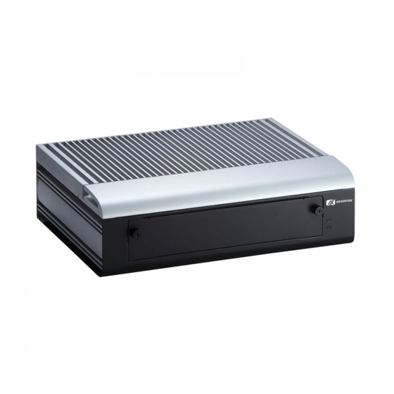
Series User’s Manual CHAPTER 1 INTRODUCTION This chapter contains general information and detailed specifications of the tBOX320-852-FL. The Chapter 1 includes the following sections: General Description System Specification Dimensions I/O Outlets Package List General Description The tBOX320-852-FL is an embedded system that supports onboard ®... - Page 10 Series User’s Manual Reliable and Stable Design The tBOX320-852-FL adopts the advanced cooling system and supporting the CompactFlash™, which makes it especially suitable for vibration environments, best for industrial automation, digital signage and gaming application. Embedded O.S. Supported ®...
-
Page 11: System Specifications
Series User’s Manual System Specifications 1.2.1 Onboard Intel® Core™2 Duo processor SP9300 (6M Cache, 2.26 GHz, 1066 MHz FSB) Onboard Celeron® M Processor ULV 723 (1M Cache, 1.20 GHz, 800 MHz FSB) BIOS American Megatrends Inc. BIOS. -
Page 12: System Specification
Series User’s Manual 1.2.3 System Specification W atchdog Timer Reset supported; 255 levels, 1~255 sec. Power Supply 12~32 V DC-in power supply (default as +24V) Power Rate:12-32Vdc,6.67-2.5A(80W) or 24Vdc,3.34A Operation Temperature -25℃ ~ 55℃ (-13 ºF ~ 130ºF) ... -
Page 13: I/O Port Address Map
Series User’s Manual 1.2.4 I/O Port Address Map The tBOX320-852-FL can communicate via I/O ports. There are total 1KB port addresses (under OS WinXP) available for assignment to other devices via I/O expansion cards. Introduction... - Page 14 Series User’s Manual Introduction...
-
Page 15: Interrupt Controller
Series User’s Manual 1.2.5 Interrupt Controller The tBOX320-852-FL series is a 100% PC compatible system. It consists of 16 interrupt request lines, and four out of them can be programmable. The mapping list under XP OS of the 16 interrupt request lines is shown as the following table. -
Page 16: Driver Cd Content
Series User’s Manual 1.2.6 Driver CD Content Chipset Driver Graphic Drivers Audio Drivers Ethernet Driver User Manual Quick Manual Introduction... -
Page 17: Dimensions
Series User’s Manual Dimensions The following diagrams show you dimensions and outlines of the tBOX320-852-FL. 1.3.1 System Dimension Introduction... -
Page 18: I/O Outlets
Series User’s Manual I/O Outlets The following figures show you I/O outlets on front view of the tBOX320-852-FL. Front View Front View drawing Introduction... - Page 19 Series User’s Manual Rear View Rear View drawing Introduction...
-
Page 20: Packing List
Series User’s Manual Packing List The package bundled with your tBOX320-852-FL should contain the following items: tBOX320-852-FL System Unit x 1 tBOX320-852-FL Quick Manual x 1 CD x 1 (For Driver and User’s Manual) Screws pack ... -
Page 21: Chapter 2 Hardware Installation
Series User’s Manual CHAPTER 2 HARDWARE INSTALLATION The tBOX320-852-FL is convenient for your various hardware configurations, such as HDD (Hard Disk Drive), CompactFlash card and Express Mini Card. The chapter 2 will show you how to install the hardware. - Page 22 Series User’s Manual Step 3) Remove the bottom cover. Step 4) Loosen screws of HDD bracket Hardware Installation...
- Page 23 Series User’s Manual Step 5) Remove the HDD bracket, and assembly the HDD bracket together with the SATA HDD Step 6) Install the HDD back to chassis and fasten the screws. Hardware Installation...
- Page 24 Series User’s Manual Step 7) Connect SATA cable and power cable to SATA HDD. Step 8) Close the bottom cover to the chassis, and fasten all screws. Hardware Installation...
-
Page 25: Installing The Swappable Sata Hdd
Series User’s Manual Installing the swappable SATA HDD Step 1) Turn off the system, and unplug the power cord. Step 2) Locate thumb screw at the front side, loosen screws. Step 3) Remove the HDD/CF Card cover. Hardware Installation... - Page 26 Series User’s Manual Step 4) Loosen screws of HDD bracket Hardware Installation...
- Page 27 Series User’s Manual Step 5) Stick the HDD handhold malar with HDD Step 6) Assembly the HDD bracket together with the SATA HDD Hardware Installation...
- Page 28 Series User’s Manual Step 7) Install the HDD bracket into the system carefully Step 8) Fasten the screw of HDD bracket Hardware Installation...
- Page 29 Series User’s Manual Step 8) Close the HDD/CF Card cover of the chassis, and fasten all screws. Hardware Installation...
-
Page 30: Installing The Compactflash
Series User’s Manual Installing the CompactFlash Step 1) Turn off the system, and unplug the power cord. Step 2) Locate thumb screw at the front side, loosen screws. Step 3) Remove the HDD/CF Card cover. Hardware Installation... - Page 31 Series User’s Manual Step 4 Slide CF card into CF slot cautionly Hardware Installation...
- Page 32 Series User’s Manual ) Close the HDD/CF Card cover of the chassis, and fasten Step 5 all screws. Hardware Installation...
-
Page 33: Installing The Express Mini Card
Series User’s Manual Installing the Express Mini Card Step 1) Turn off the system, and unplug the power cord. Step 2) Turn the system upside down to locate screws at the bottom, loosen screws. Hardware Installation... - Page 34 Series User’s Manual Step 3) Remove the bottom cover. Step 4) Loosen screws of HDD brackets Hardware Installation...
- Page 35 Series User’s Manual Step 5) Remove all HDD brackets to locate the Express Mini Card slot The right slot contains an internal SIM card slot which can support 2G/3G/4G modules. Hardware Installation...
- Page 36 Series User’s Manual Step 6) Slide Mini card into MiniCard slot cautionly Step 7) Fasten screw of Express Mini Card. Hardware Installation...
- Page 37 Series User’s Manual Step 8) Assembly the HDD brackets backs and fasten all screws. Step 9) Close the bottom cover to the chassis, and fasten all screws. Hardware Installation...
- Page 38 Series User’s Manual MEMO: Hardware Installation...
-
Page 39: Chapter 3 Jumper Setting & Connector
Series User’s Manual CHAPTER 3 Jumper Setting & Connector Proper jumper settings configure the tBOX320-852-FL to meet your application purpose. We are herewith listing a summary table of all jumpers and default settings for onboard devices, respectively. SBC layout Component Side Jumper Setting &... - Page 40 Series User’s Manual Solder Side NOTE: We strongly recommended that you should not modify any unmentioned jumper setting without Axiomtek FAE’s instruction. Any modification without instruction might cause system to become damage. Jumper Setting & Connector...
-
Page 41: Jumper Setting Summary
Series User’s Manual Jumper Setting Summary Proper jumper settings configure the tBOX320-852-FL to meet your application purpose. We are herewith listing a summary table of all jumpers and default settings for onboard devices, respectively. Jumper Default Setting Jumper Setting... -
Page 42: Pin7 Of Sata2 Connector Selection Jumper (Jp3)
Series User’s Manual 3.2.2 Pin7 of SATA2 Connector Selection Jumper (JP3) The jumper is to select the voltage or GND for SATA interface. It is used to set SATA connector (SATA2) PIN 7, to be with voltage 5V or GND. -
Page 43: Cmos Clear Jumper (Jp5)
Series User’s Manual 3.2.4 CMOS Clear Jumper (JP5) You may need to use this jumper is to clear the CMOS memory if incorrect settings in the Setup Utility. Description Function Jumper Setting Normal (Default) CMOS Clear Clear CMOS Jumper Setting & Connector... -
Page 44: Connectors
Connectors connect the CPU card with other parts of the system. Loose or improper connection might cause problems. Make sure all connectors are properly and firmly connected. Here is a summary table shows you all connectors on the tBOX320-852-FL Series. External Connectors Section VGA &... -
Page 45: Vga & Dvi Connector
Series User’s Manual 3.3.1 VGA & DVI Connector CN19A is the upper connecoer with a DB15 connector commonly used for the CRT Monitor. Signal Signal Signal Green Blue N.C. DETECT N.C. DDC DATA Horizontal Sync Vertical Sync DDC CLK CN19B is the lower connector, DVI-D connector for the digital visual interface display. - Page 46 Series User’s Manual Signal Signal TX2- TX2+ Ground No use No use DVI_SPD_CLK DVI_SPD DATA No use TX1- TX1+ Ground No use No use VGAVCC Ground FPDETECT TX0- TX0+ Ground NO use No use Ground TXC+ TXC- CN19B Jumper Setting & Connector...
-
Page 47: Serial Port Connector
Series User’s Manual 3.3.2 Serial Port Connector COM1~COM4 Port connector standard DB-9 connector.The pin assignment of RS-232/RS-422/RS-485 is listed on the following table. If you need COM port to support RS-422 or RS-485, please selection to the BIOS items. - Page 48 Series User’s Manual COM2 RS-232 RS-422 RS-485 No use No Use DCD, Data carrier detect No Use RXD, Receive data Data+ TXD, Transmit data No use No Use DTR, Data terminal ready No use No Use GND, ground No use...
- Page 49 Series User’s Manual COM3 RS-232 RS-422 RS-485 No use No Use DCD, Data carrier detect No Use RXD, Receive data Data+ TXD, Transmit data No use No Use DTR, Data terminal ready No use No Use GND, ground No use...
- Page 50 Series User’s Manual COM4 RS-232 RS-422 RS-485 No use No Use DCD, Data carrier detect No Use RXD, Receive data Data+ TXD, Transmit data No use No Use DTR, Data terminal ready No use No Use GND, ground No use...
-
Page 51: Audio Phone Jack Connector
Series User’s Manual 3.3.3 Audio Phone Jack Connector After installing onboard audio driver, you may connect speaker to Line Out jack, microphone to MIC in jack. Signal Ground (GND) MIC_L_IN MIC_L_IN1 MIC_R_IN1 MIC_R_IN LINE_OUT_L LINE_OUT_L1 LINE_OUT_R1 LINE_OUT_R 3.3.4 USB2.0 Stack Ports... -
Page 52: Led Indicators
Series User’s Manual 3.3.5 LED Indicators The LED indicator (LED1) on this board is for show HDD/power on/LAN1 status. Signal Signal LED1 1 +3.3V 3 +3.3V HDD_ACTIVE# 5 +3.3V LAN1_Active# 7 LAN1_LINK100# LAN1_LINK1000# The LED indicator (LED2) on this board is for show the LAN2 status. -
Page 53: Atx Power On/Off Button
Series User’s Manual 3.3.6 ATX Power On/OFF Button The ATX power button is on the I/O side. It can allow users to control tBOX320-852-FL power on/off. Signal PSIN 3.3.7 DC Power Input connector The DC Power Input connector Signal... -
Page 54: M12-8Pin Lan Connector (Lan1, Lan2)
Series User’s Manual 3.3.8.2 M12-8pin LAN Connector (LAN1, LAN2) The M12-8pin LAN Connector is A-Code type which can support 10/100/1000Mbps 10/100 Mbps 1000 Mbps MDI 2+ MDI 3+ MDI 3- TX - MDI 0- RX + MDI 1+ TX +... -
Page 55: Digital I/O Connector
Series User’s Manual 3.3.9 Digital I/O Connector The tBOX320-852-FL support an isolated 6-in/2-out Digital I/O (DIO) Signal Signal DI_COM DI 0 DI 1 DI 2 DI 3 DI 4 DI 5 DIO_GND DO_COM+ DO 0 DO 1 DO_COM- NOTE: Please refer to Appendix B for more information about Digital I/O Jumper Setting &... -
Page 56: Sim Card Connector
Series User’s Manual 3.3.10 SIM Card Connector The SIM Card slot (CN4) is a ISO 7816 standard 6-pin connector for PCI Express Mini Card (CN6) used. Signal SIM_PWR LOCK SIM_RESET SIM_CLK OPEN SIM_VPP SIM_DATA 3.3.11 PCI-Express Mini Card Connector The CN5 is a PCI Express Mini Card connectors with support for a PCI Express x1 link and a USB 2.0 link. - Page 57 Series User’s Manual Signal Signal W AKE# +3.3VSB No use No use +1.5V CLKREQ# No use No use No use REFCLK- No use REFCLK+ No use No use No use +3.3VSB PERST# PE_RXN4 +3.3VSB PE_RXP4 +1.5V SMB_CLK PE_TXN4 SMB_DATA...
- Page 58 Series User’s Manual The CN6 is a PCI Express Mini Card connectors with support for a PCI Express x1 link and a USB 2.0 link , it also connectos to a SIM card slot(CN4). A PCI Express Mini Card can be applied to either PCI Express or USB 2.0.
- Page 59 Series User’s Manual Signal Signal W AKE# +3.3VSB No use No use +1.5V UIM_PW R CLKREQ# UIM_DATA UIM_CLK REFCLK- UIM_RESET REFCLK+ UIM_VPP No use No use +3.3VSB PERST# PE_RXN3 +3.3VSB PE_RXP3 +1.5V SMB_CLK PE_TXN3 SMB_DATA PE_TXP3 USB_D4- USB_D4+ +3.3VSB +3.3VSB...
- Page 60 Series User’s Manual Jumper Setting & Connector...
-
Page 61: Compactflash™ Socket
Series User’s Manual 3.3.12 CompactFlash™ Socket The tBOX320-852-FL is equipped with a CompactFlash disk type-II socket on the solder side to support an IDE interface CompactFlash disk card with DMA mode supported. The socket is especially designed to avoid incorrect installation of th e CompactFlash disk card. - Page 62 Series User’s Manual Signal Signal Address 0 DASP# Data 0 PDIAG# Data 1 Data 8 Data 2 Data 9 IOCS16# Data 10 CD2# 1 2 3 4 5 6 7 8 9 10 11 12 13 14 15 16 17 18 19 20 21 22 23 24 26 27 28 29 30 31 32 33 34 35 36 37 38 39 40 41 42 43 44 45 46 47 48 49 Jumper Setting &...
-
Page 63: Sata Connector
Series User’s Manual 3.3.13 SATA Connector The SATA connectors are for high-speed SATA interface ports and they can be connected to hard disk devices. Signal SATA_TX+ SATA_TX- SATA_RX- SATA_RX+ 3.3.14 SATA Power Connector Signal +5 VDC +5 VDC +5 VDC... - Page 64 Series User’s Manual MEMO: Jumper Setting & Connector...
-
Page 65: Chapter 4 Ami Bios Setup Utility
Series User’s Manual CHAPTER 4 AMI BIOS SETUP UTILITY This chapter provides users with detailed description about how to set up basic system configuration through the AMI BIOS setup utility. Starting To enter the setup screens, follow the steps below: Turn on the computer and press the <Del>... -
Page 66: Navigation Keys
Series User’s Manual Navigation Keys The BIOS setup/utility uses a key-based navigation system called hot keys. Most of the BIOS setup utility hot keys can be used at any time during the setup navigation process. These keys include <F1>, <F10>, <Enter>, <ESC>, <Arrow> keys, and so on. -
Page 67: Main Menu
Series User’s Manual Main Menu System Time/Date Use this option to change the system time and date. Highlight System Time or System Date using the <Arrow> keys. Enter new values through the keyboard. Press the <Tab> key or the <Arrow> keys to move between fields. -
Page 68: Advanced Menu
Series User’s Manual Advanced Menu The Advanced menu allows users to set configuration of the CPU and other system devices. You can select any of the items in the left frame of the screen to go to the sub menus: ... - Page 69 Series User’s Manual Configure advanced CPU settings This screen shows the CPU Configuration, and you can change the value of the selected option. Intel ® C-State tech Use this item to enable or disable the Intel® C-State technology.
- Page 70 Series User’s Manual IDE Configuration Use this screen to select options for the IDE Configuration and change the value of the selected option. Available options of the selected item appear on the right side of the screen. For items marked with “”, please press <Enter>...
- Page 71 Series User’s Manual Super IO Configuration Use this screen to select options for the Super IO Configuration, and change the value of the selected option. Serial Port1 Address This item specifies the base I/O port address and Interrupt Request address of serial port 1.
- Page 72 Series User’s Manual COM1 RS Mode This item specifies the mode of COM1. The default setting is RS232 COM2 RS Mode This item specifies the mode of COM2. The default setting is RS232 COM3 RS Mode This item specifies the mode of COM3.
- Page 73 Series User’s Manual Hardware Health Configuration This screen shows the Hardware Health Configuration, which displays the temperature of System and Vcore, +12V, +5V, +3.3V. AMI BIOS Setup Utility...
- Page 74 Series User’s Manual ACPI Settings Use this screen to select options for the ACPI Settings, and change the value of the selected option. General ACPI Configuration Scroll this item and press <Enter> to view the General ACPI...
- Page 75 Series User’s Manual General ACPI Configuration/Suspend mode Allow you to select the Advanced Configuration and Power Interface(ACPI) state to be used for system suspend. Here are the options for your selection, S1(POS), S3(STR) and Auto. AMI BIOS Setup Utility...
- Page 76 Series User’s Manual USB Configuration You can use this screen to select options for the USB Configuration, and change the value of the selected option. USB Device Wakeup From S3/S4 Use this item to Disable or Enable the USB keyboard /Mouse...
- Page 77 Series User’s Manual AHCI Settings Use this screen to select options for the AHCI Settings, and change the value of the selected option. It will display SATA HDD information. AMI BIOS Setup Utility...
- Page 78 Series User’s Manual Configuration Remote Access type and parameters Use this screen to select options for console port Remote Access Use this item to Disable or Enable the console redirection function which allow user to remote access system.
-
Page 79: Boot Menu
Series User’s Manual Boot Menu The Boot menu allows users to change boot options of the system. You can select any of the items in the left frame of the screen to go to the sub menus: Boot Settings Configuration ... - Page 80 Series User’s Manual Boot Settings Configuration Quick Boot Enabling this item lets the BIOS skip some power on self tests (POST). The default setting is Enabled. Quiet Boot Enabling this item lets the BIOS skip some power on self tests (POST).
- Page 81 Series User’s Manual Hit ‘DEL’ Message Display If this item is enabled, the system displays the message “Press DEL to run Setup” during POST. The default setting is Enabled. Interrupt 19 Capture If this item is enabled, this function makes the option ROMs to trap Interrupt 19.
- Page 82 Series User’s Manual Hard Disk Drives Use this screen to view the hard disk drives in the system. AMI BIOS Setup Utility...
- Page 83 Series User’s Manual LAN Boot Configuration Use these items to enable or disable the Boot ROM function of the onboard LAN chip when the system boots up. Available options of the selected item appear on the right side of the screen.
-
Page 84: Security Menu
Series User’s Manual Security Menu The Security menu allows users to change the security settings for the system. Supervisor Password This item indicates whether a supervisor password has been set. If the password has been installed,『 Installed』 displays. -
Page 85: Chipset Menu
Series User’s Manual Chipset Menu The Chipset menu allows users to change the advanced chipset settings. You can select any of the items in the left frame of the screen to go to the sub menus: North Bridge Configuration ... - Page 86 Series User’s Manual North Bridge Configuration Boots Graphic Adapter Priority When using multiple graphics cards, this item can select which graphics controller to be the primary display device during boot. Internal Graphics Mode Select This item allows you to select the amount of system memory used by the internal graphics device.
- Page 87 Series User’s Manual Video Function Configuration DVMT Mode Select Allow you to select DVMT (Dianomic Video Memory Technology) mode and Fixed Mode. DVMT/FIXED Memory Allow you to allocate a fixed amount of system memory as graphics memory.
- Page 88 Series User’s Manual South Bridge Configuration HDA Controller This item allows you to enable or disabled the HD audio support. CMOS Backup When CMOS loss, system will load CMOS default setting. The default setting is Disable.
-
Page 89: Exit Menu
Series User’s Manual Exit Menu The Exit menu allows users to load the system configuration with optimal or failsafe default values. AMI BIOS Setup Utility... - Page 90 Series User’s Manual Save Changes and Exit When you have completed the system configuration changes, select this option to leave Setup and reboot the computer so the new system configuration parameters can take effect. Select Save Changes and Exit from the Exit menu and press <Enter>.
-
Page 91: Appendix Awatchdog Timer
Series User’s Manual APPENDIX A WATCHDOG TIMER What is Watchdog Timer The integrated W atchdog Timer can be set up by programming. There are 1~255 levels available. As long as the vaule of timer is set, after enabling, the countdown of the value is starting. It needs to reset or disable watchdog, otherwise auto-reset will be running when the value is counted to 0. - Page 92 Series User’s Manual ;Activate WDT: dx,2Eh al,30h dx,al dx,2Fh al,01h dx,al ;Set Second or Minute : dx,2Eh al,F5h dx,al dx,2Fh al,Nh ;N=00h or 08h(See below Note) dx,al ;Set base timer : dx,2Eh al,F6h dx,al dx,2Fh al, Mh ;M=00h,01h,02h,..FFh (Hex),Value=0 to 255 dx, al ;...
- Page 93 Series User’s Manual Sample of Watchdog application Assume there is program A which needs to maintain running in a system. The value of W atchdog Timer must be set bigger than the running time of program A. Then, after the running time of program A is finished, either to disable or to reset watchdog timer.
- Page 94 Series User’s Manual MEMO: Watchdog Timer...
-
Page 95: Appendix Bdigital I/O
Series User’s Manual APPENDIX B DIGITAL I/O Digital I/O Software Programming Digital Input/Output Assembler Sample Code ;Start set DIO program: dx,4Eh al,87h ;Un-lock super I/O dx,al dx,al dx,4Eh al,29h dx,al dx,4Fh al,02h dx,al dx,4Eh al,2Ah dx,al dx,4Fh al,01h... - Page 96 Series User’s Manual Digital Input ; Set DI0~DI5 as input pins. dx,4Eh al,E3h dx,al dx,4Fh al,3Fh dx,al ; Read DI0~DI5 value. dx,4Eh al,E4h dx,al dx,4f N, DX Note1) Digital Output ; Set DO0~DO1 as output pins. dx,4Eh...
- Page 97 Series User’s Manual Note1: The N has 6bits. Every bit’s value is either “1” or “0”. " 1" means that the bit is input high. " 0" means that the bit is input low. 1. N=00h=00000000b GPIO27 GPIO26 2. N=20h=00100000b.
- Page 98 Series User’s Manual MEMO: Watchdog Timer...
-
Page 99: Appendix C Digital I/O Wiring
Series User’s Manual APPENDIX C DIGITAL I/O Wiring Digital I/O Specification Output Inputs: 2 x Digital Output: DO Power Input: DO_COM+ and DO0 Operating Voltage Range is specified within +12V~24V Max. 200mA per channel. Input Inputs: 6 x Digital Input:... - Page 100 Series User’s Manual Digital Input Wiring Dry Contact Dry Contact Watchdog Timer...
- Page 101 Series User’s Manual Digital Output Wiring Watchdog Timer...
- Page 102 Series User’s Manual MEMO: Watchdog Timer...
Need help?
Do you have a question about the tBOX320-852-FL Series and is the answer not in the manual?
Questions and answers