Table of Contents
Advertisement
Quick Links
Advertisement
Table of Contents

Related Manuals for AXIOMTEK tBOX311-820-FL Series


Summary of Contents for AXIOMTEK tBOX311-820-FL Series
- Page 1 Series Embedded System User’s Manual...
- Page 2 Axiomtek does not make any commitment to update the information in this manual. Axiomtek reserves the right to change or revise this document and/or product at any time without notice. No part of this document may be reproduced, stored in a retrieval...
- Page 3 Before getting started, please read the following important safety precautions. User should not modify any unmentioned jumper setting without Axiomtek FAE’s instruction. Any modification without instruction might cause system to become damage The tBOX311-820-FL does not come equipped with an operating system.
-
Page 4: Classification
Classification Degree of production against electric shock: not classified Degree of protection against the ingress of water: IP40 Equipment not suitable for use in the presence of a flammable anesthetic mixture with air or with oxygen or nitrous oxide. Mode of operation: Continuous General Cleaning Tips You may need the following precautions before you begin to clean the computer. - Page 5 Cleaning Tools: Although many companies have created products to help improve the process of cleaning your computer and peripherals users can also use household items to clean their computers and peripherals. Below is a listing of items you may need or want to use while cleaning your computer or computer peripherals.
- Page 6 If the computer equipments need the maintenance or are beyond repair, we strongly recommended that you should inform your Axiomtek distributor as soon as possible for the suitable solution. For the computers that are no longer useful or no longer working well, please contact your Axiomtek distributor for recycling and we will make the proper arrangement.
-
Page 7: Table Of Contents
Table of Contents Disclaimers ..................ii Safety Precautions ................iii Classification ..................iv CHAPTER 1 INTRODUCTION ............1 General Description ..............1 System Specifications ............. 3 1.2.1 CPU ................3 1.2.2 System I/O ..............3 1.2.3 System Specification ........... 4 1.2.4 Driver CD Content ............ - Page 8 Control Keys .............. 29 Getting Help .............. 30 The Main Menu ............31 Standard CMOS Setup Menu ........32 Advanced BIOS Features ......... 34 Advanced Chipset Features ........41 Integrated Peripherals ..........44 4.10 PnP/PCI Configuration Setup ........54 4.11 PC Health Status ............
-
Page 9: Chapter 1 Introduction
Series User’s Manual CHAPTER 1 INTRODUCTION This chapter contains general information and detailed specifications of the tBOX311-820-FL. The Chapter 1 includes the following sections: General Description System Specification Dimensions I/O Outlets Package List General Description The tBOX311-820-FL is an embedded system that supports onboard ®... - Page 10 Series User’s Manual Reliable and Stable Design The tBOX311-820-FL adopts the advanced cooling system and supporting the CompactFlash™, which makes it especially suitable for vibration environments, best for transportation applications. Embedded O.S. Supported ® The tBOX311-820-FL not only supports Windows XP, but ®...
-
Page 11: System Specifications
Series User’s Manual System Specifications 1.2.1 Onboard Intel® Atom™ processor Z520PT (1.33 GHz) BIOS Phoenix AwardBIOS. System Memory One 200-pin SO-DIMM support DDR2 400/533MHz max. up to 2GB Graphics Intel GMA500 graphics Core integrate in US15W PT 1.2.2... -
Page 12: System Specification
Series User’s Manual 1.2.3 System Specification Watchdog Timer Reset supported; 255 levels, 1~255 sec. Power Supply DC12V mode: Operating voltage: DC9 ~ 16V Start voltage: DC12V or higher DC24V mode: Operating voltage: DC18 ~ 32V Start voltage: DC24V or higher ... -
Page 13: Driver Cd Content
Series User’s Manual 1.2.4 Driver CD Content Chipset Driver Graphic Drivers Audio Drivers Ethernet Driver User Manual Quick Manual CANBUS Command User Manual CANBUS Programmer’s Guide CANBUS Library AXCAN CANBUS diagnostic tool... -
Page 14: Dimensions
Series User’s Manual Dimensions The following diagrams show you dimensions and outlines of the tBOX311-820-FL. Introduction... -
Page 15: I/O Outlets
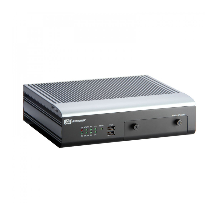
Series User’s Manual I/O Outlets The following figures show you I/O outlets on front view of the tBOX311-820-FL. Front View Front View drawing Introduction... - Page 16 Series User’s Manual Rear View Rear View drawing CANBUS Introduction...
-
Page 17: Packing List
Series User’s Manual Packing List The package bundled with your tBOX311-820-FL should contain the following items: tBOX311-820-FL System Unit x 1 tBOX311-820-FL Quick Manual x 1 CD x 1 (For Driver and User’s Manual) Screws pack ... - Page 18 Series User’s Manual MEMO: Introduction...
-
Page 19: Chapter 2 Hardware Installation
Series User’s Manual CHAPTER 2 HARDWARE INSTALLATION The tBOX311-820-FL is convenient for your various hardware configurations, such as HDD (Hard Disk Drive), CompactFlash card and Express Mini Card. The chapter 2 will show you how to install the hardware. - Page 20 Series User’s Manual Step 3) Loosen screws of HDD bracket. Step 4) Stick the HDD handhold malar with HDD, assembly the HDD bracket together with the SATA HDD Hardware Installation...
- Page 21 Series User’s Manual Step 5) Install the HDD bracket into the system carefully, and fasten the screw of HDD bracket Step 6) Close the HDD/CF Card cover of the chassis, and fasten all screws. Hardware Installation...
-
Page 22: Installing The Sim Card And Express Mini Card
Series User’s Manual Installing the SIM Card and Express Mini Card. Step 1) Turn off the system, and unplug the power cord. Step 2) Turn the system upside down to locate screws at the bottom, loosen screws. Hardware Installation... - Page 23 Series User’s Manual Step 3) Remove the bottom cover. Step 4) Install SIM card into SIM card slot in right direction Hardware Installation...
- Page 24 Series User’s Manual Step 4) Slide Mini card into MiniCard slot cautiously. Step 7) Fasten screw of Express Mini Card. Hardware Installation...
-
Page 25: Chapter 3 Connectors
Connectors connect the CPU card with other parts of the system. Loose or improper connection might cause problems. Make sure all connectors are properly and firmly connected. Here is a summary table shows you all connectors on the tBOX311-820-FL Series. External Connectors Section... -
Page 26: Vga Connector
Series User’s Manual VGA Connector CN19A is the upper connecoer with a DB15 connector commonly used for the CRT Monitor. Signal Signal Signal Green Blue N.C. DETECT N.C. DDC DATA Horizontal Sync Vertical Sync DDC CLK Serial Port Connector The COM Port connector is a standard DB-9 connector.The pin... -
Page 27: Audio Phone Jack Connector
Series User’s Manual Audio Phone Jack Connector These two audio jacks ideal are for Audio Mic-In and Audio Line-out. Signal Microphone In Line Out USB2.0 Stack Ports Pin Signal USB Port 0 Pin Signal USB Port 6 USB VCC... -
Page 28: Led Indicators
Series User’s Manual LED Indicators Status W W AN W LAN P1~4 BIOS Power W W AN W LAN Programmi Bright process ng by user. done activated activated flash active CANBUS connector Signal Isolated GND Isolated_GND CAN_L Chassis_GND CAN Data L... -
Page 29: Dc Power Input Connector
Series User’s Manual DC Power Input connector There are three pins of the DC-in connector as below table Description Definination For DC power in V+. For DC power in V- For ACC (Ignition) LAN Connector (LAN1, LAN2) The system is equipped with a RJ-45 connector for Gigabit LAN. -
Page 30: Digital I/O Connector
Series User’s Manual Digital I/O Connector The tBOX311-820-FL support an isolated 4-in/4-out Digital I/O (DIO) Signal (CN3) Signal (CN2) EXT. COM- COM+ Data In 0 Data Out 0 Data In 1 Data Out 1 Data In 2 Data Out 2... -
Page 31: Sim Card Connector
Series User’s Manual 3.10 SIM Card Connector The SIM Card slot (SCN3) is a ISO 7816 standard 6-pin connector for PCI Express Mini Card (SCN4) used. Signal SIM_PWR LOCK SIM_RESET SIM_CLK OPEN SIM_VPP SIM_DATA 3.11 PCI-Express Mini Card Connector(SCN4,5,6) - Page 32 Series User’s Manual Signal Signal USB_D3- USB_D3+ +3.3VSB +3.3VSB LED_W W AN# LED_W LAN# No use LED_W PAN# No use +1.5V No use No use +3.3VSB NOTE SCN6 only support USB2.0 Connectors...
-
Page 33: Compactflash™ Socket
Series User’s Manual 3.12 CompactFlash™ Socket The tBOX311-820-FL is equipped with a CompactFlash disk type-II socket on the solder side to support an IDE interface CompactFlash disk card with DMA mode supported. The socket is especially designed to avoid incorrect installation of the CompactFlash disk card. - Page 34 Series User’s Manual Signal Signal Address 0 DASP# Data 0 PDIAG# Data 1 Data 8 Data 2 Data 9 IOCS16# Data 10 CD2# 1 2 3 4 5 6 7 8 9 10 11 12 13 14 15 16 17 18 19 20 21 22 23 24...
-
Page 35: Sata Connector
Series User’s Manual 3.13 SATA Connector The SATA connectors are for high-speed SATA interface ports and they can be connected to hard disk devices. Signal SATA_TX+ SATA_TX- SATA_RX- SATA_RX+ 3.14 SATA Power Connector Signal +5 VDC +5 VDC +5 VDC... - Page 36 Series User’s Manual MEMO: Connectors...
-
Page 37: Chapter 4 Phoenix-Award Bios Utility
CHAPTER 4 PHOENIX-AWARD BIOS UTILITY The Phoenix-Award BIOS provides users with a built-in Setup program to modify basic system configuration. All configured parameters are stored in a flash-backed-up to save the Setup information whenever the power is turned off. Entering Setup There is one way to enter the Setup program. -
Page 38: Getting Help
Series User’s Manual Getting Help Main Menu The online description of the highlighted setup function is displayed at the bottom of the screen. Status Page Setup Menu/Option Page Setup Menu Press <F1> to pop out a General Help Window that provides the description of using appropriate keys and possible selections for highlighted items. -
Page 39: The Main Menu
’ tBOX311-820-FL Series User s Manual The Main Menu Once you enter the Award BIOS CMOS Setup Utility, the Main Menu appears on the screen. In the Main Menu, there are several Setup functions and a couple of Exit options for your selection. Use arrow keys to select the Setup Page you intend to configure then press <Enter>... -
Page 40: Standard Cmos Setup Menu
Series User’s Manual Standard CMOS Setup Menu The Standard CMOS Setup Menu displays basic information about your system. Use arrow keys to highlight each item, and use <PgUp> or <PgDn> key to select the value you want in each item. - Page 41 ’ tBOX311-820-FL Series User s Manual IDE Primary Master/Primary Slave These items identify the types of each IDE channel installed in the computer, so, IDE type is auto detection. Video Select the display adapter type for your system.
-
Page 42: Advanced Bios Features
Series User’s Manual Advanced BIOS Features This section allows you to configure and improve your system, to set up some system features according to your preference. Phoenix-Award BIOS Utility... - Page 43 ’ tBOX311-820-FL Series User s Manual CPU Features Scroll to this item and press <Enter> to view the CPU Feature sub menu. Phoenix-Award BIOS Utility...
- Page 44 Series User’s Manual Harddisk boot priority Scroll to this item and press <Enter> to view the sub menu to decide the disk boot priority Phoenix-Award BIOS Utility...
- Page 45 ’ tBOX311-820-FL Series User s Manual System System requires correct password before booting, and also before permitting access to the Setup page. Setup System will boot, but requires correct password before permitting access to Setup. (Default value) Phoenix-Award BIOS Utility...
- Page 46 Series User’s Manual NOTE To disable the security, select PASSWORD SETTING at Main Menu and then you will be asked to enter a password. Do not type anything, just press <Enter> and it will disable the security. Once the security is disabled, the system will boot and you can enter Setup freely.
- Page 47 ’ tBOX311-820-FL Series User s Manual APIC Mode APIC (Advanced Programmable Interrupt Controller) mode is enabled that provides symmetric multiprocessing (SMP) for systems. NOTE APIC Mode has been locked and cannot be modified. Phoenix-Award BIOS Utility...
- Page 48 Series User’s Manual MPS Version Control For OS This item specifies the version of the Multiprocessor Specification (MPS). Version 1.4 has extended configuration tables to improve support for multiple PCI bus configurations and provide future expandability. Press <Esc> to return to the Main Menu page.
-
Page 49: Advanced Chipset Features
’ tBOX311-820-FL Series User s Manual Advanced Chipset Features This section contains completely optimized chipset’s features on the board that you are strongly recommended to leave all items on this page at their default values unless you are very familiar with the technical specifications of your system hardware. - Page 50 Series User’s Manual DRAM Timing Selectable Use this item to increase the timing of the memory. This is related to the cooling of memory. System BIOS Cacheable Selecting Enabled allows caching of the system BIOS ROM at F0000h-FFFFFh, resulting in better system performance.
- Page 51 ’ tBOX311-820-FL Series User s Manual Boot Type (CRT Only) This item is to select Display Device that the screen will be shown. But its default is CRT Only and cannot be modified. Panel Scaling (AUTO by default)
-
Page 52: Integrated Peripherals
Series User’s Manual Integrated Peripherals This section allows you to configure your OnChip IDE Device, Onboard Device, SuperIO Device and USB Device Setting. Phoenix-Award BIOS Utility... - Page 53 ’ tBOX311-820-FL Series User s Manual OnChip IDE Device Scroll to this item and press <Enter> to view the sub menu OnChip IDE Device. IDE HDD Block Mode Block mode is also called block transfer, multiple commands, ormultiple sectors read/write. If your IDE hard drive supports...
- Page 54 Series User’s Manual Phoenix-Award BIOS Utility...
- Page 55 ’ tBOX311-820-FL Series User s Manual Onboard Device Scroll to this item and press <Enter> to view the sub menu Onboard Device. Intel HD Audio Controller Choose Auto to Disabled an Intel HD Audio controller. SDIO/MC Controller (Enabled)
- Page 56 Series User’s Manual Press <Esc> to return to the Integrated Peripherals page. Phoenix-Award BIOS Utility...
- Page 57 ’ tBOX311-820-FL Series User s Manual Super IO Device Onboard Serial Port 1/2 Select an address and corresponding interrupt for the serial port. There are several options for your selection. Press <ESC> to return to the Integrated Peripherals page...
- Page 58 Series User’s Manual Phoenix-Award BIOS Utility...
- Page 59 ’ tBOX311-820-FL Series User s Manual Phoenix-Award BIOS Utility...
- Page 60 Series User’s Manual USB Device Setting Scroll to this item and press <Enter> to view the sub menu USB Device Setting. Press <Esc> to return to the Integrated Peripherals page. Onboard Lan Boot ROM Use this item to enable or disable the Boot ROM function of the onboard LAN chip when the system boots up.
- Page 61 ’ tBOX311-820-FL Series User s Manual Power Management Setup The Power Management Setup allows you to save energy of your system effectively. It will shut down the hard disk and turn OFF video display after a period of inactivity. ...
-
Page 62: Pnp/Pci Configuration Setup
Series User’s Manual 4.10 PnP/PCI Configuration Setup This section describes the configuration of PCI (Personal Computer Interconnect) bus system, which allows I/O devices to operate at speeds close to the CPU speed while communicating with other important components. This section covers very technical items that only experienced users could change default settings. - Page 63 ’ tBOX311-820-FL Series User s Manual Resources Controlled By The Award Plug and Play BIOS can automatically configure all boot and Plug and Play-compatible devices. If you select Auto, all interrupt request (IRQ), DMA assignment and Used DMA fields disappear as the BIOS automatically assign them.
- Page 64 Series User’s Manual Phoenix-Award BIOS Utility...
- Page 65 ’ tBOX311-820-FL Series User s Manual IRQ Resources When resources are controlled manually, assign each system interrupt to one of the following types in accordance with the type of devices using the interrupt: 1. Legacy ISA Devices compliant with the original PC AT bus specification, requiring a specific interrupt (such as IRQ4 for serial port 1).
- Page 66 Series User’s Manual Maximum Payload Size When using DDR SDRAM and Buffer size selection, another consideration in designing a payload memory is the size of the buffer for data storage. Maximum Payload Size defines the maximum TLP (Transaction Layer Packet) data payload size for the device.
- Page 67 ’ tBOX311-820-FL Series User s Manual Phoenix-Award BIOS Utility...
-
Page 68: Pc Health Status
Series User’s Manual 4.11 PC Health Status This section supports hardware monitoring that lets you monitor those parameters for critical voltages, temperatures and fan speed of the board. Press <Esc> to return to the Main Menu page. Phoenix-Award BIOS Utility... -
Page 69: Load Optimized Defaults
’ tBOX311-820-FL Series User s Manual 4.12 Load Optimized Defaults This option allows you to load your system configuration with default values. These default settings are optimized to enable high performance features. To load CMOS SRAM with SETUP default values, please enter “Y”. If not, please enter “N”. -
Page 70: Set Supervisor/User Password
Series User’s Manual 4.13 Set Supervisor/User Password You can set a supervisor or user password, or both of them. The differences between them are: Supervisor password: You can enter and change the options on the setup menu. User password: You can just enter, but have no right to change the options on the setup menu. - Page 71 ’ tBOX311-820-FL Series User s Manual Phoenix-Award BIOS Utility...
-
Page 72: Save & Exit Setup
Series User’s Manual 4.14 Save & Exit Setup This section allows you to determine whether or not to accept your modifications. Type “Y” to quit the setup utility and save all changes into the CMOS memory. Type “N” to bring you back to the Previous Setup utility. -
Page 73: Exit Without Saving
’ tBOX311-820-FL Series User s Manual 4.15 Exit Without Saving Select this option to exit the Setup utility without saving changes you have made in this session. Type “Y”, and it will quit the Setup utility without saving your modifications and come back to Previous Setup utility. - Page 74 Series User’s Manual MEMO: Phoenix-Award BIOS Utility...
-
Page 75: Appendix Awatchdog Timer
’ tBOX311-820-FL Series User s Manual APPENDIX A WATCHDOG TIMER About Watchdog Timer Software stability is major issue in most applications. Some embedded systems are not watched by human for 24 hours. It is usually too slow to wait for someone to reboot when computer hangs. The systems need to be able to reset automatically when things go wrong. - Page 76 Series User’s Manual ;Select W DT Function: dx,2Eh al,2Dh dx,al dx,2Fh al,20h dx,al ;Activate WDT: dx,2Eh al,30h dx,al dx,2Fh al,01h dx,al ;Set Second or Minute : dx,2Eh al,F5h dx,al dx,2Fh al,Nh ;N=00h or 08h(See below Note) dx,al ;Set base timer :...
- Page 77 ’ tBOX311-820-FL Series User s Manual ;Disable WDT: dx,2Eh al,30h dx,al dx,2Fh al, 00h ;Can be disable at ant time dx,al Note: When N’s value is 00h, the time base is set second. M = 00: Time-out Disable 01: Time-out occurs after 1 second...
- Page 78 Series User’s Manual Watchdog Timer...
-
Page 79: Appendix Bdigital I/O
’ tBOX311-820-FL Series User s Manual APPENDIX B DIGITAL I/O Digital I/O Software Programming I2C to GPIO PCA9535PW GPIO Group0[3:0] is input, Group0[7:4] is output. I2C address: 0b0100000x. Registers: Register 0: Input Group0 register. Register 2: Output Group0 register. - Page 80 Series User’s Manual MEMO: Digital I/O...
-
Page 81: Appendix C Digital I/O Wiring
’ tBOX311-820-FL Series User s Manual APPENDIX C DIGITAL I/O Wiring Digital I/O Specification Digital I/O Port support 4bits input and 4bits output. Digital Input(CN3): Voltage rating: 0 ~ 30Vdc. Vil: +/-5Vdc max.(COM to DI). - Page 82 Series User’s Manual Digital Input D/W Switch in “D” tBox311 Internal Wet Contact Sink mode Support Ext. Power + Int. PWR Power Ext. Power - Switch Ext. Power - Switch Digital Input tBox311 Internal D/W Switch in “W” Wet Contact Source mode Support Ext.
- Page 83 ’ tBOX311-820-FL Series User s Manual DO Connection Example: Digital Output tBox311 Internal Ext. Power + Relay Ext. Power - Digital I/O Wiring...
- Page 84 Series User’s Manual MEMO: Digital I/O Wiring...
-
Page 85: Appendix D Power On Procedure
’ tBOX311-820-FL Series User s Manual APPENDIX D Power On Procedure tBOX311-820-FL is an embedded system which is designed for vehicle, and supports both vehicle with +12V car battery or +24V car battery. The boot up requirement is quite different from normal embedded system. -
Page 86: Power Input Mode Setting
Series User’s Manual Power Input Mode Setting To support different vehicle and battery protection, it has two types of power Input mode: Start Very Low Operating Low Voltage Mode Voltage Voltage Voltage 9V~16V 11.5V 10.5V 18V~32V *Start Voltage: The intelligent power board will start up and initial whole system when DC power source higher than this setting. -
Page 87: Dc-Inlet Introduction
’ tBOX311-820-FL Series User s Manual DC-inlet Introduction There are three pins of the DC-in connector as below table: Definination Description For DC power in V+. For DC power in V- For ACC (Ignition) ACC means “accessories”. Mainly, it acts both notice signal to all electronical devices, and also provides DC from battery. -
Page 88: Power On Cabling Example
Series User’s Manual Power on cabling example Due to the voltage of ACC is usually the same as V+, user could connect V+ with ACC to initial the tBOX311-820-FL. Power On without ACC control: ACC connect to V+. Power On with ACC control: ACC connector to ignition switch.
Need help?
Do you have a question about the tBOX311-820-FL Series and is the answer not in the manual?
Questions and answers