
Subscribe to Our Youtube Channel
Related Manuals for King Industrial KC-EB100


Summary of Contents for King Industrial KC-EB100
-
Page 1: Instruction Manual
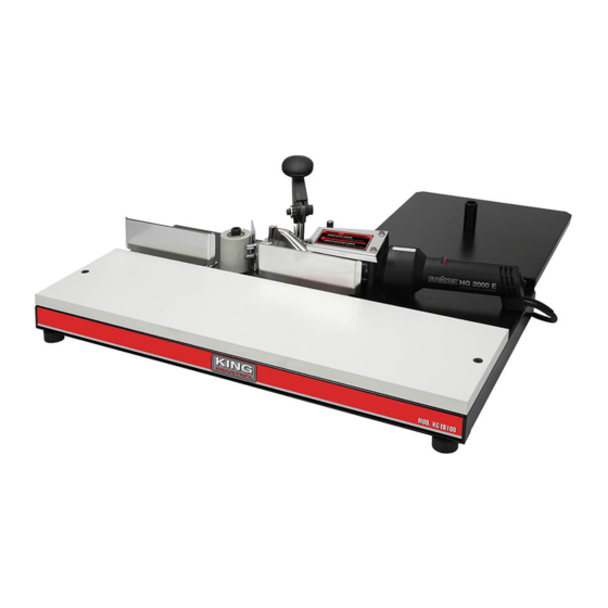
EDGE BANDER MODEL: KC-EB100 INSTRUCTION MANUAL COPYRIGHT © 2018 ALL RIGHTS RESERVED BY KING CANADA TOOLS INC. -
Page 2: Warranty Information
WARRANTY INFORMATION 2-YEAR kING CANADA TOOLS LIMITED WARRANTY OFFERS A 2-YEAR LIMITED WARANTY FOR NON COMMERCIAL USE. FOR THIS EDGE BANDER PROOF OF PURCHASE Please keep your dated proof of purchase for warranty and servicing purposes. PARTS DIAGRAM & PARTS LISTS Refer to the Parts section of the King Canada web site for the most updated parts diagram and parts list. -
Page 3: General Safety Instructions
GENERAL SAFETY INSTRUCTIONS VOLTAGE WARNING: Before connecting the tool to a power source (receptacle, outlet, etc.) be sure the voltage supplied is the same as that specified on the nameplate of the tool. A power source with voltage greater than that for the specified tool can result in SERIOUS INJURY to the user - as well as damage to the tool. -
Page 4: Specific Safety Instructions
SPECIFIC SAFETY INSTRUCTIONS SPECIFIC SAFETY RULES Safety is a combination of common sense, staying alert and knowing how your Edge Bander and heat gun works. Read and understand the following safety rules before operating. keep Away From Flammables or Combustibles Never operate this tool near flammables or combustibles. -
Page 5: Electrical Information
ELECTRICAL INFORMATION ELECTRICAL INFORMATION WARNING: YOUR EDGE BANDER COMES WITH A HEAT GUN WHICH MUST BE CONNECTED TO A 120V, 15-AMP. BRANCH CIRCUIT. GROUNDED CURRENT 120V OPERATION 120V OUTLET CARRYING As received from the factory, the heat gun PRONGS supplied with this Edge Bander is ready to run for 120V operation. - Page 6 6. Upper guide 13. Heat gun variable temperature dial 7. Heat gun nozzle 14. Heat gun on/off switch Specifications Model ......................KC-EB100 Maximum thickness ....................2” Voltage ..................120V, 1 phase, 60Hz Motor ....................1500W, 12.5 Amp. Variable temperature settings ..............49 C to 593...
- Page 7 ASSEMBLY ASSEMBLY Installing Rear Support Table & Support Post 1. Remove the two cap screws and washers (A) Fig.3 at the rear of the Edge Bander base. FIGURE 3 2. Tilt the Edge Bander and install rear support table (A) Fig.4 to the base (B) as shown using the two cap screws and washers (C).
- Page 8 ADJUSTMENTS ADJUSTMENTS Adjusting Upper & Lower Guides 1) The upper guides (A) Fig.7 and lower guides (B) can be adjusted by loosening the cap screws (C) using the 5mm hex. key. 2) The lower guides (A) should be set slightly below the work table, once adjusted, no further adjustments should be necessary.
-
Page 9: Operation
OPERATION OPERATION Steinel® Heat Gun Controls 1) The Steinel heat gun (A) Fig.11 comes with ® an on/off switch (B) at the end of the handle. Push switch downwards to turn heat gun On, push switch upwards to turn heat gun Off. 2) The Steinel heat gun also comes with a ®... - Page 10 OPERATION OPERATION GUIDELINE continued... 6) Plug the heat gun power cord into a 120V power source and push the On/Off switch upwards to turn heat gun on. Note: Allow approximately 30-40 seconds for the hot air gun to reach operating temperature.
-
Page 11: Maintenance
MAINTENANCE MAINTENANCE Cleaning 1) Accummulation of adhesive- Prolonged use of the Edge Bander may cause accumulation of adhesive on the guides, which can prevent free movement of the edge banding material. To remove this adhesive, plug in the heat gun and turn it on, with the heat gun set at medium temperature.
Need help?
Do you have a question about the KC-EB100 and is the answer not in the manual?
Questions and answers