
Related Manuals for King Industrial KC-366SH


Summary of Contents for King Industrial KC-366SH
-
Page 1: Instruction Manual
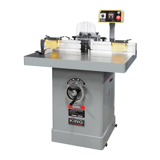
5 HP 1-1/4” INDUSTRIAL SHAPER WITH DIGITAL READOUT INSTRUCTION MANUAL MODEL: KC-366SH COPYRIGHT © 2017 ALL RIGHTS RESERVED BY KING CANADA TOOLS INC. -
Page 2: Warranty Information
WARRANTY INFORMATION 2-YEAR KING CANADA TOOLS LIMITED WARRANTY OFFERS A 2-YEAR LIMITED WARRANTY FOR THIS INDUSTRIAL SHAPER FOR COMMERCIAL USE. PROOF OF PURCHASE Please keep your dated proof of purchase for warranty and servicing purposes. PARTS DIAGRAM & PARTS LISTS Refer to the Parts section of the King Canada web site for the most updated parts diagram and parts list. -
Page 3: General Safety Instructions
GENERAL SAFETY INSTRUCTIONS VOLTAGE WARNING: Before connecting the machine to a power source (receptacle, outlet, etc.) be sure the voltage supplied is the same as that specified on the nameplate. A power source with voltage greater than specified can result in SERIOUS INJURY to the user - as well as damage the machine. -
Page 4: Electrical Information
ELECTRICAL INFORMATION WARNING ALL ELECTRICAL CONNECTIONS MUST BE DONE BY A QUALIFIED ELECTRICIAN. FAILURE TO COMPLY MAY RESULT IN SERIOUS INJURY! ALL ADJUSTMENTS OR REPAIRS MUST BE DONE WITH THE MACHINE DISCONNECTED FROM THE POWER SOURCE. FAILURE TO COMPLY MAY RESULT IN SERIOUS INJURY! POWER SUPPLY Starting and Stopping the Industrial Shaper WARNING: YOUR INDUSTRIAL SHAPER MUST BE CONNECTED... -
Page 5: Specifications
7. Safety guard lock knob (1 of 2) 29. Outfeed ram fin adjustment knob 8. Safety guard 30. Fence 4” dust chute 9. Control panel SPECIFICATIONS MODEL KC-366SH Spindle diameter 3/4”, 1-1/4” Spindle speeds 5,000, 7,000 & 10,000 RPM Table size 39-5/16” x 31-7/16”... -
Page 6: Assembly And Adjustments
ASSEMbLY & ADJUSTMENTS UNPACKING, CLEANING AND SETTING UP This Industrial Shaper weighs approximately 640 pounds. Do not overexert yourself while unpacking or moving this machine. The Industrial Shaper is bolted to the wooden base, remove hex. bolts and 90º plates and use a forklift or heavy-duty pallet truck to lift the Industrial Shaper off the base. - Page 7 ASSEMbLY & ADJUSTMENTS Installing and using starter pin Warning! Use of the starting pin should only be attempted by advanced users. If you have never used this method, it is recommended you get training from a qualified person. Failure to comply may result in serious injury. The starting pin (A) Fig.8 &...
- Page 8 ASSEMbLY & ADJUSTMENTS INSTALLING/REMOVING SPINDLE Spindle Assembly Installation The fence guard (A) Fig.11 has been removed for clarity. The spindle assembly (B) is mounted to the arbor (C) and secured with a draw bar (D) and nut (E). Use the following procedure to install the spindle assembly. Reverse the order to remove the spindle.
- Page 9 ASSEMbLY, ADJUSTMENTS & OPERATION SHAPER CUTTER INSTALLATION continued... Unlocking spindle 5. Pull out the spindle lock (A) Fig.12 accessible through the door on the right side of the cabinet. Rotate 90º right or left, resetting the knob into the indent. Using gloves to prevent injury from the shaper cutter, turn the spindle by hand to verify that it turns freely.
- Page 10 ADJUSTMENTS & OPERATION ADJUSTMENTS & OPERATION Changing Cutter Speed This Industrial Shaper is equipped with pulleys that allow you to change the spindle speed. The belt (A) Fig.18 placed on the upper pulleys (B) provides 5,000 RPM spindle speed. Placing the belt on the middle pulleys (C) provides 7,000 RPM spindle speed.
- Page 11 ADJUSTMENTS & OPERATION ADJUSTMENTS & OPERATION Control box This Industrial Shaper is equipped with a control box provided with ON/OFF push buttons, a FWD/REV switch and a Spindle Height Digital Readout. See Fig.21. WARNING: Make sure that your workplace is inaccessible to children by closing and locking all entrances when you are away.
-
Page 12: Operation
OPERATION Operational guidelines Cutter Rotation Counterclockwise Setup – With the cutter installed as shown in A, Fig.23, feed the workpiece from right to left. Clockwise Setup – With the cutter installed as shown in B, Fig.23, feed the workpiece from left to right. FIGURE 23 Using the Fence Using the fence is the safest and most satisfactory method of shaping, and... - Page 13 OPERATION Operational guidelines Straight Edge Shaping Straight edge shaping is always performed with the workpiece against the fence. Use only push sticks and holddowns to keep the workpiece in position. Warning: Do not use the miter gauge to feed material along the fence face. The workpiece can bind and cause kickback.
- Page 14 OPERATION Operational guidelines Straight Line bevel Shaping To shape a beveled straight edge, use a bevel-edge shaping jig in combination with the regular fence as shown in Fig.31. FIGURE 31 To perform a bevel-edge cut, the infeed edge of the jig is placed against the infeed fence and clamped to the table as shown in Fig.32.
- Page 15 OPERATION Operational guidelines Contour Edge Shaping With Collar continued... If the workpiece is to be shaped all around the perimeter, hold it firmly and push the work straight into the cutter until the depth of cut is established by the collar as shown in Fig.36.
- Page 16 OPERATION Operational guidelines Arcs and Circles Large circular and arc-shaped stock can be shaped as described in section named Contour Edge Shaping. However, smaller sized stock requires the use of special shaping jigs similar to those shown in Fig.42. With the entire fence assembly removed, carefully position the jig for desired depth-of-cut and securely clamp to the table.
- Page 17 OPERATION Operational guidelines Securing the Template There are various methods used to secure the template to the workpiece. The experienced operator will choose the most appropriate according to the shape, size and type construction of the template. For example, if the workpiece is large enough to extend beyond the front of the table and still leave room for the desired cut, it can be securely held to the template with "C"...
- Page 18 OPERATION Operational guidelines Sash and Door Shaping continued... • Fig.53 shows both cuts required for a window sash rail end. The first operation at top is a rabbet cut made with a groove cutter. The second operation is performed with a stub spindle and buttonhead screw. butt Joints All butt-type joints require both workpieces to be perfectly square and FIGURE 53...
-
Page 19: Operation And Maintenance
OPERATION & MAINTENANCE Operational guidelines Tenon The tenon fixture illustrated in Fig.58 shows a miter gauge equipped with a hold-down for shaping the ends of narrow workpieces. The miter gauge can also be adapted to cut square and centred tenons at the ends of legs for tables, chairs, etc.
Need help?
Do you have a question about the KC-366SH and is the answer not in the manual?
Questions and answers