
Related Manuals for Aruba 8360 Series


Summary of Contents for Aruba 8360 Series
- Page 1 Aruba 8360 Switch Series Installation and Getting Started Guide Published: May 2022 Edition: 2...
- Page 2 Copyright Information © Copyright 2022 Hewlett Packard Enterprise Development LP. Open Source Code This product includes code licensed under the GNU General Public License, the GNU Lesser General Public License, and/or certain other open source licenses. A complete machine-readable copy of the source code corresponding to such code is available upon request.
-
Page 3: Table Of Contents
Power-on the switch and check LEDs Power off the switch Mount the Switch Two-post Rack Mount Option Four-Post Rack Mount Option Install Transceivers Connect the Switch to a Power Source Setup for Initial Configuration Aruba 8360 Switch Series | Installation and Getting Started Guide... - Page 4 Environmental Specifications Acoustics RoHS Safety and Regulatory Information Connectivity Standards Cabling and Technology Information Cabling Specifications Technology Distance Specifications Support and other resources Accessing Aruba Support Accessing Updates Aruba Support Portal My Networking Warranty Information Regulatory Information Documentation Feedback Contents...
-
Page 5: About This Document
Aruba 8360-32Y4C v2 Switch (JL717C) Aruba 8360-48XT4C v2 Switch (JL720C) Aruba 8360-16Y2C v2 Switch (JL718C) Aruba 8360-12C v2 Switch (JL721C) Aruba 8360-48Y6C v2 Switch (JL719C) Aruba 8360-24XF2C v2 Switch (JL722C) Aruba 8360 Switch Series | Installation and Getting Started Guide... -
Page 6: Related Publications
Port-to-Power (Prt2Pwr) Front-to-Back (FB) Power-to-Port(Pwr2Prt) Back-to-Front (BF) Related Publications Start Here: Installation, Safety, and Regulatory Information for the Aruba 8360 Switches Transceiver Guide AOS-CX software manuals To view and download these publications, visit the Aruba Support Portal at https://asp.arubanetworks.com/downloads. About this Document... -
Page 7: Introducing The Switches
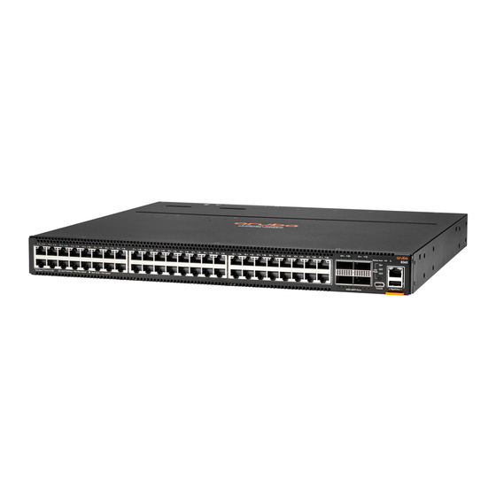
Fan trays Switch features Overview The Aruba 8360 Switch Series is a family of premium networking switches, ideal for enterprise data centers, network aggregation and core. They provide the foundation for high-performance networks supporting IoT, mobile, and cloud applications. These switches are intended for indoor use only. They are for use in commercial applications. A typical installation is in an environmentally controlled data center. - Page 8 Label Description JL700A/JL701A Aruba 8360 32Y4C JL702A/JL703A Aruba 8360 16Y2C JL706A/JL707A Aruba 8360 48XT4C JL708A/JL709A Aruba 8360 12C JL710A/JL711A Aruba 8360 24XF2C JL704C/JL705C Aruba 8360-48Y6C Figure 2 Front of all 8360 rev C switches Introducing the Switches...
- Page 9 Figure 2 Front of all 8360 rev C switches Aruba 8360 Switch Series | Installation and Getting Started Guide...
- Page 10 JL710C/JL711C Aruba 8360 24XF2C v2 Label Description SFP28 Ports For SFP28/QSFP+/QSFP28 operation, only Aruba supported Transceivers, AOCs, or DACs are allowed. For SFP/SFP+ operation, there is an Unsupported Transceiver mode available, however no warranty or support are provided for the transceiver/cable when used.
-
Page 11: Network Ports
USB-C Serial Console Port QSFP28 port indicator LEDs QSFP28 ports For SFP28/QSFP+/QSFP28 operation, only Aruba supported Transceivers, AOCs, or DACs are allowed. For SFP/SFP+ operation, there is an Unsupported Transceiver mode available, however no warranty or support are provided for the transceiver/cable when used. -
Page 12: Split Mode (Qsfp28)
Console Port Aruba 8360 switches include an RJ-45 serial console port on the rear of the switch. This port is used to connect a console to the switch by using an RJ-45 serial cable (not supplied). A DB9-to-RJ-45 console cable can be ordered from HPE: JL448A, Aruba X2C2 RJ45 to DB9 Console Cable. -
Page 13: Out-Of-Band Management (Oobm) Port
PC or workstation running a VT-100 terminal emulator, or a VT-100 terminal. The Aruba CX mobile app and the Aruba USB Bluetooth adapter enable you to configure your switch from your mobile device. For information about using the Aruba CX mobile app to configure the switch, see the Fundamentals Guide for your switch and software release. - Page 14 Label Description SFP28 ports For SFP28/QSFP+/QSFP28 operation, only Aruba supported Transceivers, AOCs, or DACs are allowed. For SFP/SFP+ operation, there is an Unsupported Transceiver mode available, however no warranty or support are provided for the transceiver/cable when used. QSFP port indicator LEDs...
- Page 15 LED mode LEDs (Spd Mode, Usr1 and Usr2Usr2 is reserved for future use) LED Mode Select Button QSFP port indicator LEDs Figure 4 Chassis and Port LEDs for the Aruba 8360 12C (JL708A/JL709A/JL721A) Aruba 8360 Switch Series | Installation and Getting Started Guide...
- Page 16 1000/100/10 Mbps Out-Of-Band-Management Port USB2.0 Type-A Port (Labeled "Aux") Luggage Tab (Contains Product and Unit Identification Info) LED mode select button USB-C Serial Console Port Figure 5 Chassis and Port LEDs for the Aruba 8360-24XF2C (JL710A/JL711A/JL722A) Label Description 24 SFP28 Ports System LEDs...
- Page 17 Luggage Tab (Contains Product and Unit Identification Info) USB-C Serial Console Port LED Mode Select Button QSFP port indicator LEDs Figure 6 Chassis and Port LEDs for the Aruba 8360-32Y4C (JL700C/JL701C/JL717C) Label Description For SFP28/QSFP+/QSFP28 operation, only Aruba supported Transceivers, AOCs, or DACs are allowed.
- Page 18 Description LED Mode Select Button USB-C Serial Console Port QSFP port indicator LEDs QSFP28 Ports (1-4) MACsec enabled ports Figure 7 Chassis and Port LEDs for the Aruba 8360-16Y2C (JL702C/JL703C/JL718C) Label Description 16 SFP28 Ports Port mode LEDs System LEDs 1000/100/10 Mbps Out-Of-Band-Management Port USB2.0 Type-A Port (Labeled "Aux")
- Page 19 1000/100/10 Mbps Out-of-Band-Management Port USB2.0 Type-A Port (Labeled "Aux") Luggage Tab (Contains Product and Unit Identification Info) 6 QSFP28 Ports (53-54 MACsec enabled) Figure 9 Chassis and Port LEDs for the Aruba 8360-48XT4C (JL706C/JL707C/JL720C) Label Description 48 10GBase-T ports Port mode LEDs...
- Page 20 1000/100/10 Mbps Out-Of-Band-Management Port USB2.0 Type-A Port (Labeled "Aux") Luggage Tab (Contains Product and Unit Identification Info) LED mode select button USB-C Serial Console Port Figure 11 Chassis and Port LEDs for the Aruba 8360-24Y2C (JL710C/JL711C/JL722C) Label Description 24 SFP28 Ports Port mode LEDs...
-
Page 21: Led Mode Select Button And Mode Leds
Indicator of traffic activity. The Green blink time is roughly proportional to the % of full bandwidth utilization of the port. Fault No fault FLASH Amber Blinks Fault synchronously with Global Status LED. Aruba 8360 Switch Series | Installation and Getting Started Guide... - Page 22 Switch LEDs Function LED State Meaning Behavior QSFP port indicator. Displays Startup OS-CX: No valid link In split mode, each Link/Activity SVOS: Off LED corresponds to or Mode 1 lane of the split. information Otherwise, all 4 LEDs for the port. are in unison.
-
Page 23: Switch Product Label
Global Status LED. Switch Product Label The switch product label is an Aruba Orange-colored tab on the bottom right side of the switch front panel. Pull the tab out to view the product label information. The product label information includes the part number, serial number, and MAC address. Serial numbers and MAC address labels are duplicated on the back or bottom of the product. -
Page 24: Back Of The Switch
All 8360 SKUs have three fan trays with the exception of 8360-48Y6C. Refer to Figure 2 in this section for more information on the rear of 8360-48Y6C switches. Figure 1 Back of Aruba 8360 Rev A & C Switches except 8360-48Y6C Label... -
Page 25: Management Ports
Power Supply Status LED Fan Trays (1-5) Optional Ground Lug mounting location Management Ports Information about the Console Port. Console Port (RJ-45) The RJ-45 console port is used for CLI serial port access. Aruba 8360 Switch Series | Installation and Getting Started Guide... -
Page 26: Power Supplies
(USB-C to USB-A adapter) to connect to a laptop with a Type-C port. Power Supplies The Aruba 8360 switch does not have a power switch; it is powered on when at least one installed power supply is connected to an active AC power source. The power supplies automatically adjust to any voltage between 100-127 and 200-240 volts and either 50 or 60 Hz. -
Page 27: Power Supply Instructions
Blue (JL713A) (Power-to-Port Airflow) The Aruba 8360 switch is shipped with two hot-swappable, field-replaceable, AC power supplies. Each power supply has a country-specific power cord for connection to an AC power outlet. The switch can operate with one active power supply. -
Page 28: Power Supply Status Led
Redundancy With power redundancy, the Aruba 8360 switch can continue normal operation even when one power supply fails or is powered off. When two power supplies are installed, if one becomes unavailable (fails, is powered off or removed) the remaining power supply provides full power for the device. -
Page 29: Fan Trays
Fan Trays The Aruba 8360 48Y6C switch is equipped with five field-replaceable, hot-swappable fan trays. Each fan tray features individual fans that pull air through the chassis from Port-to-Power or Power-to-Port. Non-8360 48Y6C SKUs identified in this document are equipped with three field-replaceable, hot-swappable fan trays. -
Page 30: Fan Tray Status Led
If multiple Fan trays have failed, the switch will power off and reboot in 5 minutes to reassess cooling capabilities. The Aruba 8360 switch is not compatible with fan trays from other Aruba hardware platforms. Fan Tray Status LED Fan tray LED... -
Page 31: Switch Features
Support for many advanced features to enhance network performance. For a description, see the OS-CX guides for your switch. Ability to update the switch software. To download product updates, go to the Aruba Support Portal. Aruba 8360 Switch Series | Installation and Getting Started Guide... -
Page 32: Installing The Switch
USB Bluetooth adapter: Enables you to configure your switch from a mobile device. Requires the Aruba CX Mobile App. For information about using the Aruba CX mobile app to configure the switch, see the Fundamentals Guide for your switch and software release. -
Page 33: Parts Not Included
#AC3, and specify the J9955A power cord as a separate line item in the order.] Parts not included If you have not already done so, order an Aruba rack mount kit for use with your 8360 switch. Rack mounting your Aruba 8360 switch is supported using these rack mount kits: JL9583B, Aruba X414 1U Universal 4-Post Rack Mount Kit (Ordered separately.) -
Page 34: Prepare The Installation Site
In the front of the switch, leave a minimum of 6 inches (15.24 cm) of space for the twisted-pair and fiber- optic cabling. In the back of the switch, leave a minimum of 6 inches (15.24 cm) of space for the power cord. Aruba 8360 Switch Series | Installation and Getting Started Guide... -
Page 35: Install Power Supplies
Cooling air flow in Aruba 8360 switches is Port-to-Power or Power-to-Port, depending on which power supply and fan tray options are installed. To reverse the cooling air flow direction in an 8360 switch, you must replace the existing power supplies and fan trays with power supplies and fan trays having the opposite air flow direction. - Page 36 1. Remove the new fan tray from its packaging, being careful to not touch any of the circuitry on the board. 2. Insert the new fan tray fully into the slot so that its face plate is flush with the back face of the switch and the latch clicks. Aruba 8360 Switch Series | Installation and Getting Started Guide...
-
Page 37: Power-On The Switch And Check Leds
Power-on the switch and check LEDs Prerequisites The Aruba 8360 switch does not contain a power on/off switch. It is turned on by connecting the AC power cord to the switch and an AC power source. Check LEDs for proper switch operation. For further detail see... -
Page 38: Two-Post Rack Mount Option
Two-post Rack Mount Option The switch is designed to be mounted in any EIA-standard 19-inch telco rack or communication equipment cabinet using the Aruba X412 1U Universal 2-Post Rack Mount Kit. For safe operation, please review the mounting precautions in... - Page 39 Mount the Switch for further detail. Figure 1 Attaching two-post mounting brackets to the switch For safe reliable installation, only use the screws provided in the accessory kit to attach the mounting brackets to the switch. The mounting brackets have multiple mounting holes and can be rotated allowing for a wide variety of mounting options.
-
Page 40: Four-Post Rack Mount Option
Four-Post Rack Mount Option The Aruba 8360 switch can be mounted in four-post racks and cabinets by using the Aruba X414 1U Universal 4-Post Rack Mount Kit (J9583B). For safe operation, please read the mounting precautions in Installation Precautions and Guidelines on page 33, before mounting a switch. -
Page 41: Install Transceivers
This can take 1-3 seconds, with the worst case being 5 seconds. The Aruba transceivers are Class 1 laser devices. Avoid direct eye exposure to the beam coming from the transmit port. The transceivers operate only at full duplex. Half duplex operation is not supported. - Page 42 Warning: in order to comply with Radiatede Emission Class A limit requirements in the United and Canada, for every 50G XCVR in a lower SFP28 port of a 8360 Series switch, an EMI plug should be inserted in the port above it.
- Page 43 JL702C, JL703C, JL718C customer entitled JL701C, to 1x of 5400-4212 JL717C JL702C, JL703C, JL718C Table 2: Aruba Switches that support EMI plugs Description EMI plug Remarks JL700C Aruba 8360- EMI plug: All odd port fr 5 to 31 32Y4C v2 FB 3F...
-
Page 44: Connect The Switch To A Power Source
2. Plug the included power cords into the power supply’s power connector and into a nearby AC power source. 3. Check the LEDs. See Chassis and Port LEDs on the front of the switch on page Aruba 8360 Switch Series | Installation and Getting Started Guide... -
Page 45: Setup For Initial Configuration
Using the Aruba CX mobile app: The Aruba CX mobile app can connect to the switch through the USB Bluetooth adapter. For information about using the Aruba CX mobile app to configure the switch, see the Fundamentals Guide for your switch and software release. -
Page 46: Connecting Cables To Transceivers
If the port LED does not come on when the network cable is connected to the port, Diagnosing with the LEDs in the Troubleshooting chapter. Ports are disabled by default. Aruba 8360 Switch Series | Installation and Getting Started Guide... -
Page 47: Initial Configuration With An Out-Of-Band Serial Connection
For more detailed information, refer to the switch software manuals for your switch. Console Cable Pinout The Aruba X2C2 RJ45 to DB9 Console Cable (JL448A) has an RJ-45 plug on one end and a DB-9 female connector on the other end. Aruba 8360 Switch Series | Installation and Getting Started Guide... -
Page 48: Rj-45 To Db-9 Pinouts
RJ-45 to DB-9 pinouts DB-9 (Signal reference from RJ-45 (Signal reference from chassis) > Reserved Reserved Reserved Reserved Reserved Initial Configuration with an Out-of-Band Serial Connection... -
Page 49: Replacing Components
If the Aruba 8360 switch is configured with a redundant power supply, the switch will not suffer any loss of traffic or performance if a power supply fails. To maintain system redundancy, a failed power supply should be replaced as soon as possible. -
Page 50: Replacing A Fan Tray
4. Connect the AC power cable to the new power supply's connector Replacing a Fan Tray The Aruba 8360 switch is equipped with three field-replaceable, hot-swappable fan trays, while the Aruba 8360-48Y6C switch is equipped with five. The switch can tolerate the failure of a single fan tray while maintaining a safe operating temperature. - Page 51 The Aruba 8360 switch is not compatible with fan trays from other Aruba hardware platforms. After removing a fan tray, wait at least five seconds before inserting a replacement fan tray in the same slot. Replace only one fan tray at a time. Removing more than one fan tray at a time compromises system cooling, risks damage to the hardware, and can cause the switch to shut down abruptly.
-
Page 52: Troubleshooting
By default, ports do not run selftest at boot. To enable port selftest on boot, save the no fastboot configuration to the switch. See AOS-CX software documentation for further detail. Diagnosing with the LEDs Aruba 8360 Switch Series | Installation and Getting Started Guide... -
Page 53: Led Patterns For General Switch Troubleshooting
LED Patterns for General Switch Troubleshooting 1. Check in the table for the LED pattern you see on your switch. 2. Refer to the corresponding diagnostic tip on the next few pages. Fan tray Diagnostic PSU1/PSU2 LEDs Global Status Back Port LED Off with power cords plugged in... - Page 54 LED is flashing has for indication of the fault condition. If a port failed selftest, contact experienced a self test, Aruba support. If there is a group speed mismatch, see EMI Plug initialization failure or group Accessory Installation on page speed mismatch.
- Page 55 Problem Solution Verify you have used the correct cable type for the connection: For fiber-optic connections, verify the transmit port on the switch is connected to the receive port on the connected device, and the switch receive port is connected to the transmit port on the connected device.
-
Page 56: Hardware Diagnostic Tests
PCs is functioning correctly. See your LAN adapter documentation for more information on running a link test or Ping test. Battery Statements: Aruba 8360 Switch Series | Installation and Getting Started Guide... - Page 57 The only indicator of battery failure is the failure of the switch internal clock to keep the correct time across a reboot or power cycle. If a battery failure occurs, contact your authorized Aruba representative for assistance. Batteries are not customer-serviceable and battery failures should be referred only to service personnel authorized by Aruba.
-
Page 58: Specifications
(JL702C) Aruba 8360-16Y2C v2 BF 3F 2AC Bdl (JL703C) 44.25 cm (17.4) 406.4 cm (16.0 in) 4.4 cm (1.73 in) 8.01 kg (17.65 lb) Aruba 8360-12C (JL721A) Aruba 8360-12C PrtToPwr Aruba 8360 Switch Series | Installation and Getting Started Guide... - Page 59 Width Depth Height Weight Configuration (JL708A) Aruba 8360-12C PwrToPrt Configuration (JL709A) Aruba 8360-12C v2 FB 3F 2AC Bdl (JL708C) Aruba 8360-12C v2 BF 3F 2AC Bdl (JL709C) 44.25 cm (17.4) 406.4 cm (16.0 in) 4.4 cm (1.73 in) 8.07 kg (17.08 lb)
-
Page 60: Electrical
Prt2Pwr3F2PS Bdl (JL710A) Aruba 8360-24XF2C v2 FB 3F 2AC Bdl (JL710C) Aruba 8360-32Y4C Aruba X391 550W Pwr2Prt3F2PS Bdl (JL701A) Pwr2Prt PSU (JL712A) Aruba 8360-32Y4C v2 BF 3F 2AC Bdl (JL701C) Aruba 8360 Switch Series | Installation and Getting Started Guide... -
Page 61: Power Cords
For a list of the power cords that apply to your switch, Included Parts. Only Aruba-approved power cords may be used with Aruba devices. To access power cord information for your switch, see Included Parts. -
Page 62: Power Consumption
If you cannot verify that you have a power cord approved for use with your switch model, contact your authorized Aruba dealer or sales representative for assistance. Remove the power cord from the switch before mounting or dismounting the switch. -
Page 63: Environmental Specifications
Switch Acoustics Aruba 8360-32Y4C PrtToPwr (JL700A) Sound Pressure (LpAm - Bystander): 45.4 dB Aruba 8360-32Y4C v2 FB 3F 2AC Bdl (JL700C) Sound Power (LWAd): 6.3 Bel Aruba 8360-32Y4C PwrToPrt (JL701A) Sound Pressure (LpAm - Bystander): 45.8 dB Aruba 8360-32Y4C v2 BF 3F 2AC Bdl (JL701C) Sound Power (LWAd): 6.4 Bel... -
Page 64: Rohs
Server, Storage, Power, Networking, and Rack Products, available at http://www.hpe.com/support/Safety- Compliance-EnterpriseProducts. Safety-EU EN 60950-1:2006 +A11:2009 +A1:2010 +A12:2011+A2:2013; EN62368-1, Ed.2:2014 Safety-Worldwide IEC 60950-1:2005+A1:2009+A2:2013; IEC 62368-1:2014 North American UL/CUL 60950-1: 2nd Edition Aruba 8360 Switch Series | Installation and Getting Started Guide... -
Page 65: Connectivity Standards
The maximum number of DAC cables supported in JL700C, JL701C, and JL717C ports 1-4 is two. Japan Power Cord Warning Connectivity Standards These connectivity standards are general and may not apply to your 8360 series switch. Compatible with these EN/IEC standard com- Technology... - Page 66 Class 1 Laser Product Laser Klasse 1 100-Gig SR4 IEEE 802.3bm 100GBASE-SR4 EN/IEC 60825 Class 1 Laser Product Laser Klasse 1 100-Gig LR4 IEEE 802.3ba 100GBASE-LR4 EN/IEC 60825 Class 1 Laser Aruba 8360 Switch Series | Installation and Getting Started Guide...
- Page 67 Compatible with these EN/IEC standard com- Technology Lasers IEEE standards pliance Product Laser Klasse 1 100-Gig DAC IEEE 802.3bj 100GBASE-CR4 40-Gig DAC IEEE 802.3ba 40GBASE-CR4 25-Gig SR IEEE 802.3by 25GBASE-SR EN/IEC 60825 Class 1 Laser Product Laser Klasse 1 25-Gig eSR (not an IEEE standard) EN/IEC 60825 Class 1 Laser...
-
Page 68: Cabling And Technology Information
This chapter includes switch connector information and network cable information for cables that should be used with Aruba 8360 switches. Incorrectly wired cabling is a common cause of problems for LAN communications. Aruba recommends that you work with a qualified LAN cable installer for assistance with your cabling requirements. -
Page 69: Technology Distance Specifications
For 10GBASE-T, Category 6 patch cables are sensitive to movement once link has been established, and could cause link to drop if moved. Therefore, Aruba recommends using Category 6A patch cables, or using cable management options to tie down (dress) the Category 6 patch cables so they cannot move. - Page 70 40GBASE-SR4 multimode fiber 1500 MHz*km 2 - 100 meters 3500 MHz*km 2 - 150 meters 40GBASE-eSR4 multimode fiber 1500 MHz*km 2 - 330 meters 3500 MHz*km 2 - 550 meters Aruba 8360 Switch Series | Installation and Getting Started Guide...
- Page 71 Supported cable Multimode fibermodal Technology Supported distances type bandwidth 40GBASE-LR4 single mode fiber 2 - 10,000 meters 40GBASE-ER4 single mode fiber 2 - 40,000 meters 40GBASE-BiDi multimode fiber 1500 MHz*km 2 - 100 meters 3500 MHz*km 2 - 150 meters 100GBASE-CR4 twinaxial copper (various lengths offered)
-
Page 72: Support And Other Resources
Other websites that can be used to find information: Airheads social forums and Knowledge https://community.arubanetworks.com/ Base Software licensing https://lms.arubanetworks.com/ End-of-Life information https://www.arubanetworks.com/support-services/end-of-life/ Aruba software and documentation https://asp.arubanetworks.com/downloads Accessing Updates To download product updates: Aruba 8360 Switch Series | Installation and Getting Started Guide... -
Page 73: Aruba Support Portal
Aruba Support Portal https://asp.arubanetworks.com/downloads If you are unable to find your product in the Aruba Support Portal, you may need to search My Networking, where older networking products can be found: My Networking https://www.hpe.com/networking/support To view and update your entitlements, and to link your contracts and warranties with your profile, go to the Hewlett Packard Enterprise Support Center More Information on Access to Support Materials page: https://support.hpe.com/portal/site/hpsc/aae/home/...
Need help?
Do you have a question about the 8360 Series and is the answer not in the manual?
Questions and answers