
Related Manuals for SMA SUNNY STRING-MONITOR


Summary of Contents for SMA SUNNY STRING-MONITOR
- Page 1 Accessories for Central inverter SUNNY STRING-MONITOR Technical Description SSM-TEN103132 | 98-4000932 | Version 3.2...
-
Page 3: Table Of Contents
Packing list ........14 Sunny String-Monitor ....... . 14 Identification of the Sunny String-Monitor. - Page 4 Connect the Data Cable Shield Contact......28 5.7.3 Connecting the Data Cable in the Sunny String-Monitor ....28 5.7.4 Connecting the Data Cable in the Sunny Central .
- Page 5 7.1.3 Detecting Sunny String-Monitor........42 7.1.4 Setting the Device Address .
- Page 6 Table of Contents SMA Solar Technology AG Reading the Measurement Values in Sunny Data Control ..57 Reading the Messages in Sunny Central Control ... 58 8.7.1 Reading and Confirming Current Messages .
-
Page 7: Notes On This Manual
Keep the documentation of the Sunny String-Monitor and of the installed components with the system documentation. They must be accessible at all times. The documents listed below are included in the delivery of your Sunny String-Monitor. The following information is contained in these documents. -
Page 8: Symbols Used
1 Notes on this manual SMA Solar Technology AG 1.4 Symbols Used The following types of safety instructions and general information appear in this document: "DANGER" indicates a hazardous situation which, if not avoided, will result in death or serious injury. "WARNING" indicates a hazardous situation which, if not avoided, could result in death or serious injury. -
Page 9: Safety
Safety 2.1 Appropriate Usage The Sunny String-Monitor is an accessory for the Sunny Central central inverter. The DC subdistributor offers the possibility of connecting several strings in parallel. The Sunny String-Monitor monitors and recognizes outages and thus prevents loss of power and output. The string fuses in the Sunny String- Monitor disconnect defective strings which, for example, have been damaged due to a short-circuit in the module or in the cabling of the PV array. -
Page 10: Parallel Connection Of Strings
2.2 Parallel Connection of Strings 2.2.1 Maximum Number of Connections per Measurement Input Several PV strings can be connected in parallel in the Sunny String-Monitor. The maximum number of PV strings connected in parallel depends on the adjustable tolerance, and can be determined as follows: N = maximum number of PV strings that can be connected in parallel. -
Page 11: Reverse Current
• Double ground fault in a module • Double ground fault in the cabling The Sunny String-Monitor contains string fuses. They trip when the string current is too high and thus protect the modules of the faulty PV strings. The Sunny String-Monitor informs Sunny Central Control of the failure of the PV strings. -
Page 12: Safety Instructions
SMA Solar Technology AG 2.3 Safety instructions Risk of lethal electric shock. • Work on the Sunny String-Monitor may only be performed after switching off the power to the unit in accordance with the regulations applicable to the installation site: – Disconnect –... -
Page 13: Information On Grounded Pv Plants
2.3.3 Reverse Voltage On the main DC cables in the Sunny String-Monitor there is a permanent reverse voltage present of up to 1000 V of the Sunny Central. When the power is off, the reverse voltage can be interrupted by pulling the DC fuses in the Sunny Central. -
Page 14: Packing List
3.2 Identification of the Sunny String-Monitor The type label serves to identify the Sunny String-Monitor. The type label is found on the mounting plate in the upper middle, next to the big measurement circuit board. On the type label there is the following information: •... -
Page 15: Structure Of The Sunny String-Monitor
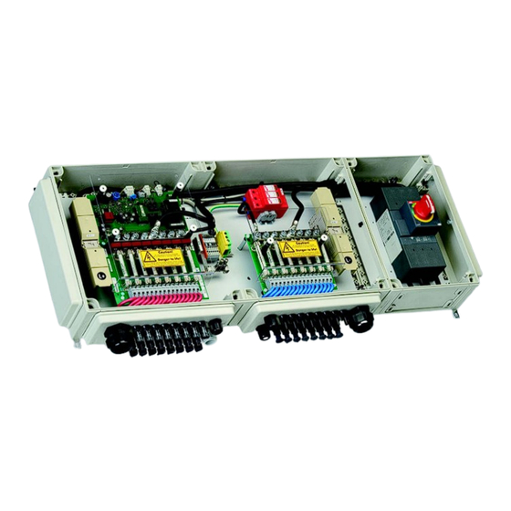
3 Packing list 3.5 Structure of the Sunny String-Monitor Depending on the option chosen, the Sunny String-Monitor may have a DC circuit breaker and may be equipped with a different number or string connections. For the selection of Sunny String-Monitor options or fittings use the option code in the price list. It determines both the assembly and recognition of the Sunny String-Monitor. - Page 16 3 Packing list SMA Solar Technology AG Position Description Communication Piggy-Back Jumper for data cable termination Piggy-Backs for data processing Operating status LEDs Overvoltage protector DC circuit breaker Connection of the feedback signal contact Shunt release drive connection Main DC cable connection, ‒ pole DC fuses or cylindrical bridges String connections, ‒...
-
Page 17: Mounting
• Do not install the Sunny String-Monitor in potentially explosive areas. • Do not install the Sunny String-Monitor in an emergency exit path, or in a living or office area. • Choose a location which can support the weight of the Sunny String-Monitor. -
Page 18: Assembling The Sunny String-Monitor
Damage to the cable glands and plug connections due to improper transport and installation. The cable glands and plug connections protrude from the enclosure. • When transporting and mounting the Sunny String-Monitor, ensure that the cable glands and plugs are not damaged. Damage to the electronics due to moisture penetration. - Page 19 SMA Solar Technology AG 4 Mounting The following graphic shows the dimensions of the Sunny String-Monitor without DC circuit breaker. 1. Mark the position of the drill holes. 2. Drill holes at the marked positions. 3. Insert floor anchors. 4. Fasten the Sunny String-Monitor to the wall or stand using suitable screws and washers.
-
Page 20: Electrical Connection
5 Electrical Connection SMA Solar Technology AG Electrical Connection 5.1 Safety Risk of lethal electric shock if the DC cable connected to the PV array is touched. The PV modules exposed to light have voltages present. • Cover the PV modules. • Follow all safety instructions of the module manufacturer. -
Page 21: Overview Of The Connection Area
SMA Solar Technology AG 5 Electrical Connection 5.2 Overview of the Connection Area 3 4 5 6 Figure 6: Terminals and plugs for connections Position Description Jumper for data cable termination Signal contact for the anti-theft protection Terminals for the connection of the feedback signal contact... - Page 22 5 Electrical Connection SMA Solar Technology AG Figure 7: Cable glands for direct connection of the PV strings to the disconnect terminals Position Description Cable gland for connection of the DC main cable, + pole Cable glands for the string connections, + pole...
-
Page 23: Closing And Opening The Sunny String-Monitor
LED 3, orange Data transfer LED 4, red Failure of the control board 5.3 Closing and Opening the Sunny String-Monitor Opening the Sunny String-Monitor 1. Turn all screw plugs 1/4 counterclockwise with a screwdriver. Push lightly while doing this. 2. Remove the cover. -
Page 24: Connecting The Pv Strings
Requirements: ☐ All cables of the PV modules are equipped with the SUNCLIX plug connectors included in delivery. Procedure: • Assemble the SUNCLIX DC plug connectors • Connect the SUNCLIX DC plug connectors to the Sunny String-Monitor SSM-TEN103132 Technical Description... - Page 25 SMA Solar Technology AG 5 Electrical Connection Assemble the SUNCLIX DC plug connectors 1. Cut the insulated conductors to length and strip 12 mm off the insulation. 2. Insert the stripped cables into the plug connector as far as they will go. Ensure the correctness of the polarity assignment and of the type of plug.
-
Page 26: Connect The Pv Strings To The Tyco, Mc3 And Mc4 Plugs
5.5 Connecting the DC Main Cable Damage to the electronics due to wrong cable installation. In order for the Sunny String-Monitor and Sunny Central to work properly, EMC guidelines must be observed. • Lay the DC main cable and the data cable separately and at a distance greater than 400 mm from one another. -
Page 27: Connecting To Ground
4. Connect the ground cable to the ground terminal. Tighten the ground terminal to 3.5 Nm torque. 5. Tighten the cable gland. 6. Ground the grounding cable in the vicinity of the Sunny String-Monitor, for example, with a ground rod. -
Page 28: Connecting The Data Cable
• Lay the DC main cable and the data cable separately and at a distance greater than 400 mm from one another. • Lay the data cable shield on both sides - in the Sunny Central and in the Sunny String-Monitor. Limited number of Piggy-Backs for data processing per hub •... - Page 29 5 Electrical Connection Parallel Connection of the Data Cables If several Sunny String-Monitor are being used, connect them in parallel. This way there will be an incoming and an outgoing data cable at every Sunny String-Monitor. The final Sunny String-Monitor is an exception. There will be only an incoming data cable connected there.
-
Page 30: Connecting The Data Cable In The Sunny Central
5.7.4 Connecting the Data Cable in the Sunny Central On all Sunny Central inverters the connection of the data cable from the Sunny String-Monitor is done at the hub. Exception: in the case of the CP series Sunny Central, the Sunny String-Monitor is connected to its own terminal strip. -
Page 31: Terminating The Data Cable
5 Electrical Connection 5.7.5 Terminating the Data Cable In each case, the last Sunny String-Monitor of a string and the last hub in the Sunny Central are terminated. The Sunny String-Monitor are not terminated on delivery, therefore they can be configured freely on- site. -
Page 32: Connecting The Remote Tripping For The Dc Circuit Breaker
5.8.1 Dimensioning the Connection Cable for the Operating Current Release Depending on the order, the Sunny String-Monitor includes a DC circuit breaker with a remote trigger. In this case, the DC circuit breaker is equipped with a shunt release. Depending on the order, the Sunny String-Monitor includes as a shunt release an operating current release or an undervoltage release. - Page 33 String-Monitor, the cable length to the voltage supply and the cable lengths between the connected Sunny String-Monitor. In a PV plant there are 20 DC switches. The greatest distance between the Sunny String-Monitor or the voltage supply is 150 m.
-
Page 34: Dimension The Connection Cable For The Undervoltage Release
5.8.2 Dimension the Connection Cable for the Undervoltage Release Depending on the order, the Sunny String-Monitor includes a DC circuit breaker with a remote trigger. In this case, the DC circuit breaker is equipped with a shunt release. Depending on the order, the Sunny String-Monitor includes as a shunt release an operating current release or an undervoltage release. -
Page 35: Connect Shunt Release
5 Electrical Connection 5.8.3 Connect Shunt Release Depending on the order, the Sunny String-Monitor includes a DC circuit breaker with a remote trigger. In this case the DC circuit breaker is equipped with a shunt release and a feedback contact. By means of the shunt release it is possible to disconnect the PV array from the inverter through the DC switch. -
Page 36: Install Anti-Theft Protection
SMA Solar Technology AG 5.9 Install Anti-Theft Protection The Sunny String-Monitor allows activation of anti-theft protection for the PV modules. Here, the contacts at the PV modules are connected to form a signal chain. Upon interruption of the signal chain, an anti-theft warning appears in the Sunny Central Control display, and an e-mail message is sent immediately. -
Page 37: Commissioning
SMA Solar Technology AG 6 Commissioning Commissioning 6.1 Commissioning the Sunny String-Monitor The commissioning report must be filled out during commissioning. The commissioning report form is enclosed with the Sunny Central. Requirements: ☐ The DC circuit breaker is disconnected. ☐ The DC main cables are connected to the inverter or DC distribution box and are activated. -
Page 38: Switching On The Sunny String-Monitor
6.2 Switching On the Sunny String-Monitor Risk of lethal electric shock. • Work on the Sunny String-Monitor may only be performed after switching off the power to the unit in accordance with the regulations applicable to the installation site. – Disconnect –... -
Page 39: Disconnecting The Sunny String-Monitor
Danger of burns by touching hot components. • Wear safety gloves during all work on the device. 1. If there is a DC circuit breaker on the Sunny String-Monitor, disconnect it. This way the Sunny String-Monitor is free of current and voltage. -
Page 40: Reconnect The Dc Circuit Breaker After Tripping
Monitor, you must switch on the DC circuit breaker again. 1. Search for the cause of the tripping, and remove it. 2. Open the Sunny String-Monitor (see chapter 5.3 ”Closing and Opening the Sunny String- Monitor”, page 23). 3. Switch the DC circuit breaker manually from the triggered position to the off position. -
Page 41: Configure Sunny String-Monitor
Procedure Check the serial interface settings at the Sunny Central section 7.1.2 Control If Sunny String-Monitor are to be detected for the first time: section 7.1.5 Deleting detected Sunny String-Monitor Detect Sunny String-Monitor section 7.1.3 Setting the device address section 7.1.4... -
Page 42: Check The Serial Interface Settings At The Sunny Central Control
2. Adopt the changes and save. 3. Check whether all the serial numbers of the Piggy-Backs for data processing are registered correctly by the measurement circuit boards of the respective Sunny String-Monitor. – Select Device Set-up > SMUs > Devices > Registration. -
Page 43: Setting The Device Address
7 Configure Sunny String-Monitor 7.1.4 Setting the Device Address To identify the measuring circuit boards in the Sunny String-Monitor, each Piggy-Back for data processing is assigned a number as "SSM identifier". This makes troubleshooting easier, for example, in the event of a string failure, or deviating string currents. The "SSM Identifier" does not correspond to the network address which is automatically assigned upon detection. -
Page 44: Configure The Sunny String-Monitor With Sunny Data Control
7.2 Configure the Sunny String-Monitor with Sunny Data Control 7.2.1 Setting the Required Values Sunny Data Control is a PC program by SMA Solar Technology AG with which you can store your PV plant data in the long term and visualize it. Sunny Data Control can be downloaded at www.SMA.de/en free of charge. - Page 45 SMA Solar Technology AG 7 Configure Sunny String-Monitor Figure 14: Window for setting of required values Position Description Tree structure "Properties" area Parameters to be set "Value" box for entering values [OK] button to save the values 1. Choose Options > Settings ☑ The "Settings" window opens.
-
Page 46: Configuring Sunny String-Monitor
Figure 15: Buttons and input windows for configuring the Sunny String-Monitor Position Description [Search] button to detect devices Labeling of the Sunny String-Monitor with the serial number of the Piggy- Back for data processing in the system tree "Parameters" tab "Parameters" area "Channel value"... - Page 47 • See Section .9 ”Troubleshooting”, page 59 3. Setting of the Device Address for each Sunny Central String-Monitor. – Sunny String-Monitor in the system tree. – In the "Parameters" area, click on SSM Identifier. – In the area "Channel value" enter a value between 1 and 40.
-
Page 48: Function Of The String Current Monitoring
380 "SMU". The information below describes how the mean value is established, what intervals are used to transmit data, and how the string current monitoring is configured. Polling intervals The Sunny String-Monitor continually measures the string currents and saves them in cycles. Sunny Central Control reads these values every 5 minutes. Group strings Individual strings can be grouped in up to 4 groups in Sunny Central Control. - Page 49 Upon confirmation at the Sunny Central Control, the error sum is reset, and the warning disappears from the display. With the flexible parameterization, the Sunny String-Monitor can detect the complete failure of a string within one polling interval. Slightly elevated string currents are reliably detected in several polling intervals and distinguished from typical current fluctuations of the PV array.
- Page 50 8 Function of the String Current Monitoring SMA Solar Technology AG Example: It is assumed that at t0 the mean value of a group is 5 A. All string currents are now compared to this mean value. If no string current lies outside the set tolerance of (e. g.) 10 %, totaling is not performed.
-
Page 51: Setting The Parameters Using Sunny Central Control
TIP: In the submenu No. of Str. All you can assign all channels of the Sunny String-Monitor to a string number of 1 to 4. This avoids having to set the number of strings for each of the individual channels, since this is automatically set for all the individual channels. -
Page 52: Setting The Groups
SMA Solar Technology AG 1. Select Device Setup > SMUs > Devices > Parameters. 2. Select Sunny String-Monitor. 3. In the submenu No. Of Strings or No. of Str. All set the number of strings connected per measuring channel used. -
Page 53: Setting The Tolerance
250 V for one hour. The supply voltage is activated as soon as the PV voltage of 250 V is reached. If overnight shutdown is deactivated, supply voltage to the Sunny String-Monitor remains on at night. This means that theft protection can be activated and evaluated, see section 8.3.7 ”Setting Anti-Theft Protection”, page 53. -
Page 54: Setting The Parameters Using Sunny Data Control
Figure 16: Buttons and input windows for parameterization of the Sunny String-Monitor Position Description Second-tier designation of the device in the system tree Labeling of the Sunny String-Monitor with the serial number of the Piggy- Back for data processing in the system tree "Parameters" tab "Parameters" area "Channel value"... -
Page 55: Setting The Groups
Sunny String-Monitor. 3. In the area "Channel value" enter the desired time of day starting at which the measuring channel or the Sunny String-Monitor should be monitored. 4. To save, select [Set]. 5. In the area "Parameter", Monitoring (X) Off for the desired channel or Monitoring Off for the complete Sunny String-Monitor. -
Page 56: Setting Overnight Shutdown
8 Function of the String Current Monitoring SMA Solar Technology AG 8.4.7 Setting overnight shutdown 1. Click on the device label at the second level in the system tree. 2. In the area "Parameter", click on SMU_Overn. Shut. 3. In the area "Channel value", select On or Off from the drop-down list. -
Page 57: Reading The Measurement Values In Sunny Data Control
Sunny String-Monitor window with the list of spot values Sunny Central Control window with the list of spot values The Sunny String-Monitor window shows the average of the individual spot values. The Sunny Central Control window shows the average values of the measurement values for each group. -
Page 58: Reading The Messages In Sunny Central Control
8 Function of the String Current Monitoring SMA Solar Technology AG 8.7 Reading the Messages in Sunny Central Control The individual meanings of the warnings and failures in the Sunny Central Control can be found in the Sunny Central user manual. Sunny Central Control resets messages which appear during a day automatically at 0:00 o'clock. -
Page 59: Troubleshooting
LED 3 does not light up Problems with the data cable. • Check data cable between Sunny for more than Central and Sunny String-Monitor, 5 minutes. and between the individual Sunny String-Monitor. LED 4 glows red. Failure of the control board of •... -
Page 60: Technical Data
10 Technical data SMA Solar Technology AG 10 Technical data Enclosure Outdoor installation Only shaded Wall mounting Material Glass-fiber reinforced plastic UV resistance Combustion properties Self-extinguishing, halogen-free Color Gray Protective insulation Mechanical Data of the Enclosure without DC Circuit Breaker Width x height x depth... - Page 61 SMA Solar Technology AG 10 Technical data Input Parameters Maximum permissible DC voltage 1 000 V DC, max Maximum permissible DC voltage with a 950 V DC, max 25 A fuse Maximum permissible DC current 130 A DC,max Number of measurement inputs...
- Page 62 10 Technical data SMA Solar Technology AG String Connection to MC4 Plug Connector Diameter 6 mm Maximum rated current 30 A String Connection to MC3 Plug Connector Diameter 4 mm Maximum rated current 20 A String Connection to Plug Connector Tyco / Electronic...
- Page 63 SMA Solar Technology AG 10 Technical data Communication Connection Type of terminal 4-conductor through terminal Cable cross-section 0.08 mm … 2.5 mm Cable gland Sealing range 8 mm … 17 mm Cable type 4 x 2 x 0.5 mm Li2YCYv (TP)
- Page 64 10 Technical data SMA Solar Technology AG Protection Rating and Ambient Conditions Protection rating IP 54 Permissible ambient temperature –25 °C ... +40 °C Rel. air humidity 15 % … 95 % Maximum altitude above sea level, AMSL 1 000 m * ...
-
Page 65: Contact
If you have technical problems with our products, please contact our Serviceline. We require the following information in order to provide you with the necessary assistance: • Type of the Sunny String-Monitor • Serial number of the Sunny String-Monitor. • Type and number of the PV modules connected • Communication method •... - Page 67 The use of supplied software produced by SMA Solar Technology AG is subject to the following conditions: • SMA Solar Technology AG rejects any liability for direct or indirect damages arising from the use of software developed by SMA Solar Technology AG. This also applies to the provision or non-provision of support activities.
Need help?
Do you have a question about the SUNNY STRING-MONITOR and is the answer not in the manual?
Questions and answers