
Related Manuals for Extron electronics Extender AAP


Summary of Contents for Extron electronics Extender AAP
- Page 1 User Guide Distribution Amplifiers Extender Series VGA-UXGA Line Drivers with Audio 68-552-01 Rev. M 01 19...
- Page 2 Safety Instructions Safety Instructions • English Istruzioni di sicurezza • Italiano AVVERTENZA: Il simbolo, , se usato sul prodotto, serve ad WARNING: This symbol, ,when used on the product, is avvertire l’utente della presenza di tensione non isolata pericolosa intended to alert the user of the presence of uninsulated dangerous all’interno del contenitore del prodotto che può...
- Page 3 , registered service marks (SM) , and trademarks (™) are the property of RGB Systems, Inc. or Extron Electronics (see the current list of trademarks on the Terms of Use page at www.extron.com): Registered Trademarks (®) Extron, Cable Cubby, ControlScript, CrossPoint, DTP, eBUS, EDID Manager, EDID Minder, Flat Field, FlexOS, Glitch Free, Global Configurator, Global Scripter, GlobalViewer, Hideaway, HyperLane, IP Intercom, IP Link, Key Minder, LinkLicense, LockIt, MediaLink, MediaPort,...
- Page 4 FCC Class A Notice This equipment has been tested and found to comply with the limits for a Class A digital device, pursuant to part 15 of the FCC rules. The Class A limits provide reasonable protection against harmful interference when the equipment is operated in a commercial environment.
- Page 5 Conventions Used in this Guide Notifications The following notifications are used in this guide: CAUTION: Risk of minor personal injury. ATTENTION : Risque de blessure mineure. ATTENTION: Risk of property damage. • • Risque de dommages matériels. NOTE: A note draws attention to important information. TIP: A tip provides a suggestion to make working with the application easier.
-
Page 7: Table Of Contents
Top, Rear, Bottom Panel Features and Cabling . 10 Extender WM AUS Template ......27 Mounting ............13 Mounting the Extender AAP or Extender AAP EX into an AAP Wallplate or Device Faceplate ......... 13 Pre-installation Testing and Troubleshooting .. 14 Mounting the Extender WM or Extender WM AAP to the Wall Box .... - Page 8 IPCP Pro Series • Contents viii...
-
Page 9: Introduction
Preparing the Site and Installing the Wall starting on page 4 in the installation section. For Extender AAP EX mounting instructions, see the user guide or installation guide for the appropriate model of Extron HSA Hideaway Surface Access enclosure. For Extender AKM MAAP mounting instructions, see the Extender AKM MAAP Installation Guide, available at http://www.extron.com. -
Page 10: Features
Features Video signal boosting — The selectable gain and peaking settings boost video signals to compensate for signal degradation caused by long cables. The Extender can send a high resolution signal up to 250 feet (75 m) through Extron M59 Series mini high resolution cable. Sync restoration —... -
Page 11: Installation
HSA Hideaway Surface Access enclosure. NOTE: The Extender AAP EX does not require a wall box if it will be installed into an Extron HSA 400 Series or HSA 800 Series surface access product. If you install an Extender AAP EX without an HSA, you must use a wall box. -
Page 12: Preparing The Site And Installing The Wall Box
You may need to install the cables into the wall, furniture, or conduits before installing the line driver. The Extender AAP or Extender AAP EX can be installed in an Extron two-gang, four- •... - Page 13 For the Extender WM, Extender WM AAP, Extender D, and the Extender AAP or • Extender AAP EX (if installed in a two- or four-gang AAP plate), attach the wall box to the wall stud or furniture with nails or screws, leaving the front edge flush with the outer wall or furniture surface.
- Page 14 For the Extender MK, pull the mounting tabs of the knockout boxforward to secure • them against the back side of the wallboard or furniture as shown in the following illustration. Pull mounting tab forward. Figure 3. Securing the MK Knockout Box to a Wall or Furniture Set the gain switch, and cable and test the line driver before fastening the line driver into the wall box.
-
Page 15: Front Panel Features And Cabling
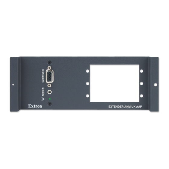
Front Panel Features and Cabling AUDIO IN COMPUTER IN EXTENDER MK EXTENDER AKM MAAP B C D AUDIO IN COMPUTER IN COMPUTER IN AUDIO IN EXTENDER WM AUS EXTENDER AKM UK AAP AUDIO IN AUDIO IN AUDIO IN COMPUTER IN COMPUTER IN COMPUTER IN EXTENDER WM AAP... - Page 16 The adapter plates allow for a variety of types of audio/video connectors or another device such as the Extender AAP to be added to the faceplate. Blank plates are included with the Extender WM AAP and Extender AKM MAAP to cover unused spaces.
- Page 17 Opening for Mini Architectural Adapter Plates (MAAPs) — The Extender AKM MAAP can have up to three optional MAAP adapter plates attached here (see figure , page 7) at one time to allow for a variety of types of audio/video connectors or another device to be added to the faceplate.
-
Page 18: Top, Rear, Bottom Panel Features And Cabling
Top, Rear, Bottom Panel Features and Cabling Extender MK, Extender AAP, Extender AAP EX, Extender WM AUS, Extender AKM UK AAP, and Extender AKM MAAP Top View Extender WM, Extender WM AAP, and Extender D Rear View Extender MK/AAP/AAP EX,... - Page 19 Sleeve(s) Extender MK, sleeve(s) to the NO Ground Here Left Tip negative (-) Extender AAP, Audio contacts. Extender AAP EX, Unbalanced Output Right Ring Extender AKM MAAP. Right Tip Sleeve(s) Left Ring Left Tip Balanced Output Right Ring Right Tip...
- Page 20 3/16 inch (5 mm) of the jacket from the wires. Do not tin the wires. Gain switch (see figure ) — At right: Extender MK, Extender AAP Extender AKM MAAP gain switch location Medium – Mid-level (access from the rear) peaking and gain...
-
Page 21: Mounting
Mounting the Extender AAP or Extender AAP EX into an AAP Wallplate or Device Faceplate The Extender AAP or Extender AAP EX and any other adapter plates must be attached to a device faceplate or AAP wallplate and cabled before the device or wallplate is pretested or installed in a wall or furniture. -
Page 22: Pre-Installation Testing And Troubleshooting
Pre-installation Testing and Troubleshooting Before mounting the line driver, test the system to make sure that the connections and settings are correct. Apply power to the line driver. The power and signal LED on the line driver lights amber to indicate that it is receiving power. If the LED does not light, check the wiring at both the line driver and the power supply, and make sure the power supply is connected to a power source. -
Page 23: Mounting The Extender Wm Or Extender Wm Aap To The Wall Box
Mounting the Extender WM or Extender WM AAP to the Wall Box Remove power from the line driver Wall Stud by disconnecting the power Screws or Nails supply. Installation Place the line driver through the Cable opening in the wall or furniture Cable and into the wall box. -
Page 24: Mounting The Extender Mk To The Knockout Box
W IT M IN Audio N IT D IO N IT RGB 468xi Laptop D IO w/ Audio Extender WM SVGA Compatible Computer w/ Audio Figure 11. An Extender WM Application Figure 10. An Extender AAP Application Extender Series • Installation... - Page 25 Projector Extron Extender AKM MAAP Line Driver Laptop Figure 12. An Extender AKM MAAP Application Extender Series • Installation...
-
Page 26: Reference Information
Dimensions NOTES: • The drawings in this section are not full size. Do not scale. • All dimensions are given in inches. Extender AAP and Extender AAP EX Dimensions 0.250” 3.000” (REF) (REF) 0.050” (REF) DETAIL A ø 0.125 THRU WITH ø... -
Page 27: Extender Wm Dimensions
Extender WM Dimensions ø 0.156 THRU WITH ø 0.290 X 82° C'SINK (2 PLACES) 0.000 0.610 1.107 ø 0.125 THRU 1.550 AUDIO IN ø 0.330 THRU WITH 2.010 ø 0.562 C'BORE 0.070 DEEP COMPUTER IN 2.570 3.392 3.890 EXTENDER WM 4.500 Extender Series •... -
Page 28: Extender Wm Aap Dimensions
Extender WM AAP Dimensions ø 0.156" THRU WITH ø 0.290" X 82° C'SINK +0.010 3.520 (4 PLACES MARKED C) -0.000 R 0.070" TOP EDGE ø 0.125" THRU 0.100 (ALL AROUND) THK. 4.500 4.500" (REF) R 0.240" 3.890 (TYP) ø 0.330" THRU WITH 3.393 ø... -
Page 29: Extender Mk Dimensions
Extender MK Dimensions R 0.070" ø 0.250" TOP EDGE DETAIL A THRU (ALL AROUND) ø 0.125" THRU ø 0.125" THRU WITH 0.060 ø 0.220" X 100° C'SINK NEAR SIDE (2 PLCS) R 0.040" (TYP) 3.380 DETAIL A 0.060" 0.984" ø 0.125" THRU 0.806 (2 PLCS) -
Page 30: Extender Akm Maap Dimensions
Extender AKM MAAP Dimensions 4X R 0.125" 2X 0.06" X 45° 2X R +0.000 3.000 -0.015 2X R 0.062 2X 2.350 2X 2.250" 1.975 2X Ø 0.150" 1.750 THRU 1.250 1.025 2X 0.750" 2X 0.650 0.000" 1.675 0.275 0.000 (0.075") Extender Series •... -
Page 31: Extender D Dimensions
Extender D Dimensions 1.290" 2X 0.062” X 45° 0.333” 0.625" 0.223” 0.399” 2X Ø 0.106" THRU 2X 0.111" BOTH SIDES 2X EXTRUSION FOR #6-32 SCREW TAPPING 2X 0.125" (0.223") Ø 0.132" THRU 2.610" Ø 0.258" THRU 2.005" 1.545" 0.984" 0.905" 0.359 0.000"... -
Page 32: Cut-Out Templates
2.79" (7.09 cm) Top Panel 2.24" (105 cm) 4.13" 4.50" (57 cm) (11.43 cm) Location of Extender AAP SURFACE Circuit Board CUT-OUT AREA FOR MOUNTING Cut Out Line for Installing the Electrical Box TEMPLATE IS FULL SIZE. Please verify dimensions prior to cutting. -
Page 33: Extender Wm Aap Template
Extender WM AAP Template Extender WM AAP Cut-Out Template for the Extron 4.5” (11.43 cm) Location of Extender AAP Circuit Board 3.86” (9.80 cm) Top Panel 6.4" 5.73” (16.3 cm) (14.55 cm) SURFACE CUT-OUT AREA FOR MOUNTING Cut Out Line for... -
Page 34: Extender Mk Template
Extender MK Template Cut-Out Template for the Extron Extender MK 3.38" (8.56 cm) Panel 1.85" (4.70 cm) 2.91" 5.70" (7.40 cm) (14.48 cm) Location of Extender Circuit Board SURFACE CUT-OUT AREA FOR MOUNTING To install an Extender MK directly into furniture, cut along this line. -
Page 35: Extender Wm Aus Template
Extender WM AUS Template Cut-out Template for the Extron Extender WM AUS 3.00" (7.62 cm) Top Panel 1.85" (4.70 cm) 2.91" Location of 4.65" Extender (7.40 cm) (11.81 cm) Circuit Board SURFACE CUT-OUT AREA FOR MOUNTING To install the Extender WM AUS directly into furniture,... - Page 36 Extron Electronics makes no further warranties either expressed or implied with respect to the product and its quality, performance, merchantability, or fitness for any particular use. In no event will Extron Electronics be liable for direct, indirect, or consequential damages resulting from any defect in this product even if Extron Electronics has been advised of such damage.
Need help?
Do you have a question about the Extender AAP and is the answer not in the manual?
Questions and answers