
Related Manuals for AXIOMTEK CEM700


Summary of Contents for AXIOMTEK CEM700
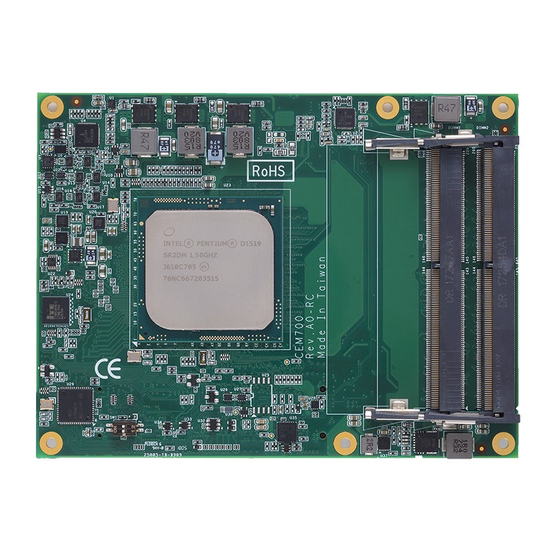
- Page 1 CEM700 ® ® ® Intel Xeon D and Pentium D Processors COM Express Type 7 Basic Module User’s Manual...
-
Page 2: Disclaimers
Axiomtek does not make any commitment to update the information in this manual. Axiomtek reserves the right to change or revise this document and/or product at any time without notice. No part of this document may be reproduced, stored in a retrieval system, or transmitted, in any form or by any means, electronic, mechanical, photocopying, recording, or otherwise, without the prior written permission of Axiomtek Co., Ltd. -
Page 3: Esd Precautions
It discharges static electricity from your body. Wear a wrist-grounding strap, available from most electronic component stores, when handling boards and components. Trademarks Acknowledgments Axiomtek is a trademark of Axiomtek Co., Ltd. ® Intel is a trademark of Intel Corporation. ®... -
Page 4: Table Of Contents
Table of Contents Disclaimers ..................... ii ESD Precautions ................... iii Chapter 1 Introduction ..........1 Features ....................1 Specifications ..................2 Utilities Supported ................3 Chapter 2 Module and Pin Assignments ....5 Module Dimensions and Fixing Holes ..........5 Module Layout .................. - Page 5 Appendix A Watchdog Timer and GPIO ....47 About Watchdog Timer ..............47 About GPIO ..................47 Appendix B BIOS Flash Utility ........ 49...
- Page 6 This page is intentionally left blank.
-
Page 7: Chapter 1 Introduction
Pentium D processors (formerly Broadwell-DE) which compatible to PICMG COM.0 Rev 3.0 specification and support dual cores or multi cores (up to 16 cores).The CEM700 was designed for customer who need high computing performance and balanced power consumptions for entry networking, micro servers or various applications. -
Page 8: Specifications
CEM700 COM Express Type 7 Basic Module Specifications ® ® ® Intel Pentium D and Xeon D BGA processors. Commercial SKUs: ® - Pentium D1508 2.2/2.6GHz 3MB, 25W (2C). ® - Xeon D1527 2.2/2.7GHz 6MB, 35W (4C). ®... -
Page 9: Utilities Supported
CEM700 COM Express Type 7 Basic Module Other Functions 4 GPO / 4 GPI. 1 SMBUS. 1 SPI. 1 LPC. Watchdog Timer: 65536 levels, 65535 secs. Power ATX: 12V±5%, 5VSB ±5%; AT: 12V±5%. - Page 10 CEM700 COM Express Type 7 Basic Module This page is intentionally left blank. Introduction...
-
Page 11: Module And Pin Assignments
CEM700 COM Express Type 7 Basic Module Chapter 2 Module and Pin Assignments Module Dimensions and Fixing Holes Top View Module and Pin Assignments... - Page 12 CEM700 COM Express Type 7 Basic Module Bottom View Module and Pin Assignments...
-
Page 13: Module Layout
CEM700 COM Express Type 7 Basic Module Module Layout Top View Module and Pin Assignments... - Page 14 CEM700 COM Express Type 7 Basic Module Bottom View Module and Pin Assignments...
-
Page 15: Installing Thermal Solution
This CPU module has six assembly holes for installing heatsink plate. Use screws to secure heatsink plate to the CEM700. Be careful not to over-tighten the screws. Module and Pin Assignments... -
Page 16: Switch Settings
Type 7 Basic Module Switch Settings Properly configure switch settings on the CEM700 to meet your application purpose. Below you can find a summary table of switch and onboard default setting. Once the default switch setting needs to be changed, please do it under power-off condition. -
Page 17: Connector
CEM700 COM Express Type 7 Basic Module Connector Signals go to the other parts of the system through connectors. Loose or improper connection might cause problems, please make sure all connectors are properly and firmly connected. Here is a summary table which shows connectors on the hardware. - Page 18 GND_C51 (FIXED) GND_D51 (FIXED) PCIE_TX5+ PCIE_RX5+ PCIE_RX16+ PCIE_TX16+ PCIE_TX5- PCIE_RX5- PCIE_RX16- PCIE_TX16- GPI0 GPO1 TYPE0# RSVD_D54 PCIE_TX4+ PCIE_RX4+ PCIE_RX17+ PCIE_TX17+ Not connected on the CEM700. CEM700 doesn’t support ESPI. The voltage of these pins is 3.3V. Module and Pin Assignments...
- Page 19 VCC_12V_4 D107 VCC_12V_10 A108 VCC_12V_5 B108 VCC_12V_11 C108 VCC_12V_5 D108 VCC_12V_11 A109 VCC_12V_6 B109 VCC_12V_12 C109 VCC_12V_6 D109 VCC_12V_12 A110 GND_A110 (FIXED) B110 GND_B110 (FIXED) C110 GND_C110 (FIXED) D110 GND_D110 (FIXED) Not connected on the CEM700. Module and Pin Assignments...
- Page 20 CEM700 COM Express Type 7 Basic Module This page is intentionally left blank. Module and Pin Assignments...
-
Page 21: Chapter 3 Hardware Description
You must install the heatsink or cooler carefully and properly to prevent damage. BIOS The CEM700 uses AMI Plug and Play BIOS with a single 128Mbit SPI Flash. System Memory The CEM700 supports two 260-pin DDR4 SO-DIMM sockets for maximum memory capacity up to 32GB. -
Page 22: I/O Port Address Map
CEM700 COM Express Type 7 Basic Module I/O Port Address Map ® The I/O port addresses (with CEB94701 baseboard under Windows 7) are as follows: Hardware Description... -
Page 23: Interrupt Controller (Irq) Map
CEM700 COM Express Type 7 Basic Module Interrupt Controller (IRQ) Map ® The interrupt controller (IRQ) mapping list (with CEB94701 baseboard under Windows 7) is shown as follows: Hardware Description... - Page 24 CEM700 COM Express Type 7 Basic Module Hardware Description...
- Page 25 CEM700 COM Express Type 7 Basic Module Hardware Description...
-
Page 26: Memory Map
CEM700 COM Express Type 7 Basic Module Memory Map ® The memory mapping list (with CEB94701 baseboard under Windows 7) is shown as follows: Hardware Description... -
Page 27: Ami Bios Setup Utility
CEM700 COM Express Type 7 Basic Module Chapter 4 AMI BIOS Setup Utility The AMI UEFI BIOS provides users with a built-in setup program to modify basic system configuration. All configured parameters are stored in a flash chip to save the setup information whenever the power is turned off. - Page 28 CEM700 COM Express Type 7 Basic Module Hot Keys Description Left/Right The Left and Right <Arrow> keys allow you to select a setup screen. The Up and Down <Arrow> keys allow you to select a setup screen or sub ...
-
Page 29: Main Menu
CEM700 COM Express Type 7 Basic Module Main Menu When you first enter the setup utility, you will enter the Main setup screen. You can always return to the Main setup screen by selecting the Main tab. System Time/Date can be set up as described below. -
Page 30: Advanced Menu
CEM700 COM Express Type 7 Basic Module Advanced Menu The Advanced menu also allows users to set configuration of the CPU and other system devices. You can select any of the items in the left frame of the screen to go to the sub menus: ►... - Page 31 CEM700 COM Express Type 7 Basic Module Ec DIO Configuration You can use this screen to select options for Digital I/O (DIO) Configuration. A description of selected item appears on the right side of the screen. For items marked with “”, please press <Enter>...
- Page 32 CEM700 COM Express Type 7 Basic Module If DIO Modification is enabled, you can load manufacture default and access to the DIO status sub screen to change inputs/outputs setting, see images below. AMI BIOS Setup Utility...
- Page 33 CEM700 COM Express Type 7 Basic Module Serial Port Configuration You can use this screen to select options for Serial Port Configuration, and change the value of the selected option. A description of the selected item appears on the right side of the screen.
- Page 34 CEM700 COM Express Type 7 Basic Module Serial Port 1 Configuration Serial Port 1 (UART1) Enable or disable serial port 1. The optimal setting for base I/O address is 248h and for interrupt request address is IRQ7. Serial Port 2 Configuration Serial Port 2 (UART2) Enable or disable serial port 2.
- Page 35 CEM700 COM Express Type 7 Basic Module Hardware Monitor This screen is for fan speed control and hardware health status monitoring. This screen displays the temperature of system and CPU, cooling fans speed in RPM and system voltages (VBAT, +3.3V, +3.3V_SBY and +5V).
- Page 36 CEM700 COM Express Type 7 Basic Module ACPI Settings You can use this screen to select options for the ACPI configuration, and change the value of the selected option. A description of the selected item appears on the right side of the screen.
- Page 37 CEM700 COM Express Type 7 Basic Module Trusted Computing You can use this screen for TPM (Trusted Platform Module) configuration. Security Device Support Enable or disable BIOS support for security device. SHA-1 PCR Bank Enable or disable SHA-1 PCR bank.
- Page 38 CEM700 COM Express Type 7 Basic Module USB Configuration USB Devices Display all detected USB devices. Mass Storage Devices Mass storage device emulation type. Auto option enumerates devices according to their media format. Optical drives are emulated as CDROM, drives with no media will be emulated according to a drive type.
- Page 39 CEM700 COM Express Type 7 Basic Module Serial Port Console Redirection You can use this screen to select options for Serial Port Console Redirection, and change the value of the selected option. A description of the selected item appears on the right side of the screen.
- Page 40 CEM700 COM Express Type 7 Basic Module UART1\UART2 Console Redirection Settings When enabled, the settings specify how the host computer and the remote computer (which the user is using) will exchange data. Both computers should have the same or compatible settings.
-
Page 41: Chipset Menu
CEM700 COM Express Type 7 Basic Module Chipset Menu The Chipset menu allows users to change the advanced chipset settings. You can select any of the items in the left frame of the screen to go to the sub menus: ►... - Page 42 CEM700 COM Express Type 7 Basic Module Processor Configuration Hyper-Threading [ALL] Enable or disable Hyper-threading Technology, which allows a single physical processor to multitask as multiple logical processors. When disabled, only one thread per enabled core is enabled. EIST (P-states) ®...
- Page 43 CEM700 COM Express Type 7 Basic Module Memory Configuration This screen displays system memory information. AMI BIOS Setup Utility...
- Page 44 CEM700 COM Express Type 7 Basic Module IIO Configuration IOU2 (IIO PCIe Port 1) Selects PCIe port Bifurcation for selected slot(s). Configuration options are x4x4, x8 and Auto. IOU1 (IIO PCIe Port 3) Selects PCIe port Bifurcation for selected slot(s). Configuration options are x4x4x4x4, x4x4x8, x8x4x4, x8x8, x16 and Auto.
- Page 45 CEM700 COM Express Type 7 Basic Module Socket 0 PcieD01F0 – Port 1A Displays IIO Pcie port status, see image below. Socket 0 PcieD03F0 – Port 3A Displays IIO Pcie port status, see image below. AMI BIOS Setup Utility...
- Page 46 CEM700 COM Express Type 7 Basic Module PCH Configuration You can use this screen to select options for PCH Configuration, and change the value of the selected option. A description of the selected item appears on the right side of the screen.
- Page 47 CEM700 COM Express Type 7 Basic Module General ME Configuration This screen displays General ME information. AMI BIOS Setup Utility...
-
Page 48: Security Menu
CEM700 COM Express Type 7 Basic Module Security Menu The Security menu allows users to change the security settings for the system. Administrator Password This item indicates whether an administrator password has been set (installed or uninstalled). User Password This item indicates whether a user password has been set (installed or uninstalled). -
Page 49: Boot Menu
CEM700 COM Express Type 7 Basic Module Boot Menu The Boot menu allows users to change boot options of the system. Setup Prompt Timeout Number of seconds to wait for setup activation key. 65535(0xFFFF) means indefinite waiting. Bootup NumLock State Use this item to select the power-on state for the keyboard NumLock. - Page 50 CEM700 COM Express Type 7 Basic Module Boot Mode Use this item for boot mode settings. UEFI Boot: Select support to boot any UEFI-capable OS. Legacy Boot: Select support to boot non UEFI-capable OS that expects a legacy BIOS interface.
-
Page 51: Save & Exit Menu
CEM700 COM Express Type 7 Basic Module Save & Exit Menu The Save & Exit menu allows users to load your system configuration with optimal or fail-safe default values. Save Changes and Exit When you have completed the system configuration changes, select this option to leave Setup and return to Main Menu. - Page 52 CEM700 COM Express Type 7 Basic Module Discard Changes Select this option to quit Setup without making any permanent changes to the system configuration. Select Discard Changes from the Save & Exit menu and press <Enter>. Select Yes to discard changes.
-
Page 53: A.1 About Watchdog Timer
CEM700 COM Express Type 7 Basic Module Appendix A Watchdog Timer and GPIO A.1 About Watchdog Timer After the system stops working for a while, it can be auto-reset by the watchdog timer. The integrated watchdog timer can be set up in the system reset mode by program. - Page 54 CEM700 COM Express Type 7 Basic Module This page is intentionally left blank. Watchdog Timer and GPIO...
-
Page 55: Appendix B Bios Flash Utility
Please read and follow the instructions below carefully. In your USB flash drive, create a new folder and name it “Axiomtek”, see figure below. Copy BIOS ROM file (e.g. CEM700.005) to “Axiomtek” folder. - Page 56 Select the USB drive containing BIOS ROM file you want to update using the <> or <> key. Then press <Enter> to get into “Axiomtek” folder. Now you can see the BIOS ROM file on the screen, press <Enter> to select.
- Page 57 CEM700 COM Express Type 7 Basic Module Please wait while BIOS completes the entire flash update process: erase data, write new data and verify data. 10. When you see the following figure, press <Enter> to finish the update process. After that the system will shut down and restart immediately.
Need help?
Do you have a question about the CEM700 and is the answer not in the manual?
Questions and answers